Another possible board - ATMega328, nRF socket, DHT22 socket, MOSFET, Uno pinout
-
@ceech Since you are the creator of this board. I am interested in how you use it. Especially how to operate this board on battery power and the power consumption..
-
@AWI Here is a graphical explanation of the socket connections:
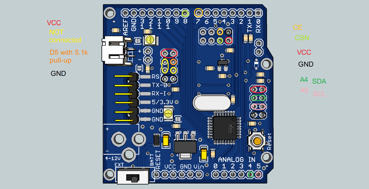
SDA and SCL lines also have pull-up resistors. They are 10k. -
how to upload custom bootloader?maybe you should put additional icsp port
-
how to upload custom bootloader?maybe you should put additional icsp port
@rachmat-aditiya27 The board is kind of hardware oriented, so I ran out of space for the ICSP header. All the needed pins are available though. Either from remaining pins of the NRF24 socket, either from digital 11, 12 and 13 header pins.
-
oh, okay got it :)
-
Hello,
I just got 2 boards and I'em trying to test them. For now I only plugged a usb/serial adapter with an ftdi to the JP3 connector to program the board. The program is simple as Serial.begin(9600); Serial.println("test");But that's not working. The programming was done successfully, and when I open the Serial monitor in the arduino ide, all I got is garbage characters. I have setup the correct communication option in the ide of course. The power VCC comes from my USB and I tried with 3.3v or 5v, but it did not change anything.
When I do the with a standard arduino mini pro, it works correctly, but not with the @ceech boards...
Any idea why and whats wrong here?
thanks -
@Raoul-Hecky said:
9600
may be a baud rate setting error.... else its possible that there is a mismatch of frequency btw the controller HW and the software it is complied for..just a thought -
Hello,
I just got 2 boards and I'em trying to test them. For now I only plugged a usb/serial adapter with an ftdi to the JP3 connector to program the board. The program is simple as Serial.begin(9600); Serial.println("test");But that's not working. The programming was done successfully, and when I open the Serial monitor in the arduino ide, all I got is garbage characters. I have setup the correct communication option in the ide of course. The power VCC comes from my USB and I tried with 3.3v or 5v, but it did not change anything.
When I do the with a standard arduino mini pro, it works correctly, but not with the @ceech boards...
Any idea why and whats wrong here?
thanks@Raoul-Hecky Did you use the Arduino Pro or Pro mini (3.3v 8mHz) w/ ATmega328 setting?
-
Hello,
I just got 2 boards and I'em trying to test them. For now I only plugged a usb/serial adapter with an ftdi to the JP3 connector to program the board. The program is simple as Serial.begin(9600); Serial.println("test");But that's not working. The programming was done successfully, and when I open the Serial monitor in the arduino ide, all I got is garbage characters. I have setup the correct communication option in the ide of course. The power VCC comes from my USB and I tried with 3.3v or 5v, but it did not change anything.
When I do the with a standard arduino mini pro, it works correctly, but not with the @ceech boards...
Any idea why and whats wrong here?
thanks@Raoul-Hecky If you can't make the board to work properly, let me know. I'll send you a replacement :)
-
I finally made them work :)
I was not using the right clock for programming, 16MHz instead of 8MHz...
Thanks @AWI ;)