CNC PCB milling
-
So I received my CNC board today. After looking over the board, I see that it has 2 endstop points per axis. Logical assumption would be that there would be one on each end of travel of an axis. I was a bit confused because my 3D printer only has 1 per axis. Do I need to use both for each axis when running GRBL?
-
So today I decided to do a little bit of testing with the CNC shield and my Y axis drive. To start off, one of the issues I have is that I do not know the specs of the motor that I have. Here is a pic:
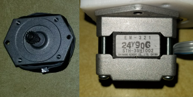
Did quite a bit of searching over the past week to try and find any information, and I can't seem to find what I need. I decided to do some tests anyway. I was able to get GRBL loaded on to the UNO board fine and connect to it through PUTTY. I then installed just the Y axis driver and connected a 12 volt power supply for starters. I was able to get the Y axis screw turning by sending some Y axis commands such as "Y20" or "Y-20". When I ran it initially I didn't have the Y axis platter mount secured to anything, so that would just spin with the screw. The problem I have is that if I hold the platter mount giving the screw even the slightest bit of resistance, the motor will spin for half a second and then start making a whining/buzzing noise and will just vibrate a bit. Once the motor starts to slow down while stopping, the screw will stop whining and spin slightly at the end of the stop. I then thought that it might be that the voltage was too low as I had read on some forums about some Epson steppers being higher voltage steppers, so I connected a 30 volt supply. Running the same test gave me the same results. Does anyone have a clue as to why this would happen? Basically the motor doesn't have any torque. -
So today I decided to do a little bit of testing with the CNC shield and my Y axis drive. To start off, one of the issues I have is that I do not know the specs of the motor that I have. Here is a pic:
Did quite a bit of searching over the past week to try and find any information, and I can't seem to find what I need. I decided to do some tests anyway. I was able to get GRBL loaded on to the UNO board fine and connect to it through PUTTY. I then installed just the Y axis driver and connected a 12 volt power supply for starters. I was able to get the Y axis screw turning by sending some Y axis commands such as "Y20" or "Y-20". When I ran it initially I didn't have the Y axis platter mount secured to anything, so that would just spin with the screw. The problem I have is that if I hold the platter mount giving the screw even the slightest bit of resistance, the motor will spin for half a second and then start making a whining/buzzing noise and will just vibrate a bit. Once the motor starts to slow down while stopping, the screw will stop whining and spin slightly at the end of the stop. I then thought that it might be that the voltage was too low as I had read on some forums about some Epson steppers being higher voltage steppers, so I connected a 30 volt supply. Running the same test gave me the same results. Does anyone have a clue as to why this would happen? Basically the motor doesn't have any torque.@dbemowsk current gets you torque, voltage gets you speed. What driver do you use? See the current setting for the driver you use, how/what voltage you measure to determine the current and the formula that links the two.
When I want to set the sweetspot (assuming driver and stepper are somewhat matched) I start low and increase the current little by little until the stepper gets warm after a few minutes. Warm, not hot! But again, the driver and stepper must match, I wouldn't try that with a Pololu A4988 and a Nema 34 stepper 😂
-
@dbemowsk current gets you torque, voltage gets you speed. What driver do you use? See the current setting for the driver you use, how/what voltage you measure to determine the current and the formula that links the two.
When I want to set the sweetspot (assuming driver and stepper are somewhat matched) I start low and increase the current little by little until the stepper gets warm after a few minutes. Warm, not hot! But again, the driver and stepper must match, I wouldn't try that with a Pololu A4988 and a Nema 34 stepper 😂
-
@dbemowsk well then check the current set by measuring Vref, plenty of tutorials on the web. If it's lower than 500mA try bumping it up little by little. Also try reducing the microsteps to 16 or 8 by removing jumpers.
-
The adjustment screw on the stepper module allows you to set max allowable current.
Also, in software, you could try setting a lower max acceleration parameter (as discussed earlier in this thread) and lower max velocity parameters, in case either or both are a factor.
You're brave to be attempting this with unknown equipment. If there are multiple factors... it's trickier to troubleshoot with no working baseline to start with.
-
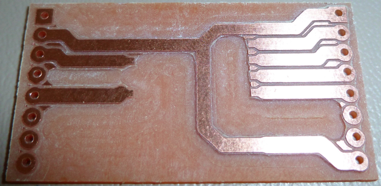
I've changed my modus operandi so that now I use the largest pad and trace sizes that I can get away with. That way, if they get whittled down during the milling, I still hopefully have enough left. :)
Example:
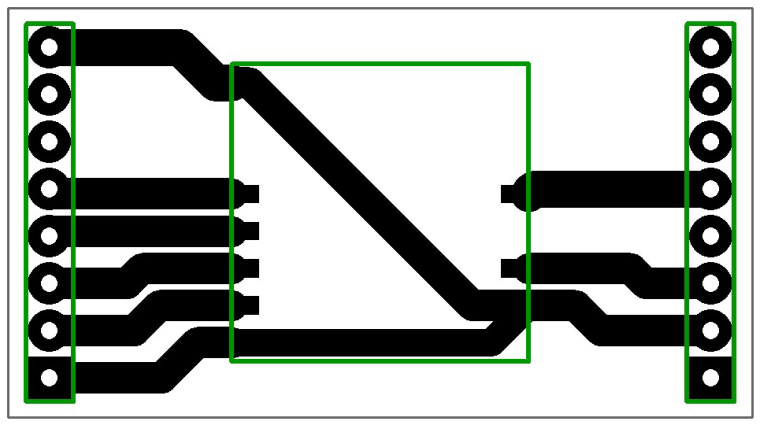
That way, I can also cut deeper and wider, which helps with soldering.
-
So good news. I was able to get the motor turning with some torque. Initially the board was set at full step resolution (no jumpers on M0, M1 or M2). I thought I'd try it at it's lowest microstep resolution which is 1/32, and the motor ran good. I checked the max current and it was set quite high at 2.035 x 2 = 4.07 A. Running some Y axis moves got the motor a bit warm, but I don't think I ran it long enough to do much damage. I now have the current down to 0.254 x 2 = 0.508 A and it seems to be running quiet and good. With it being at 1/32 microstepping it took a lot of revolutions to move the platter mount any distance, so I bumped it to 1/16 microstepping. This is mainly due to the 4.8:1 gear ratio that I have. I think this should give me some pretty good precision on the Y axis at least. Haven't built the X or Z yet, but that is next.
-
The adjustment screw on the stepper module allows you to set max allowable current.
Also, in software, you could try setting a lower max acceleration parameter (as discussed earlier in this thread) and lower max velocity parameters, in case either or both are a factor.
You're brave to be attempting this with unknown equipment. If there are multiple factors... it's trickier to troubleshoot with no working baseline to start with.
-
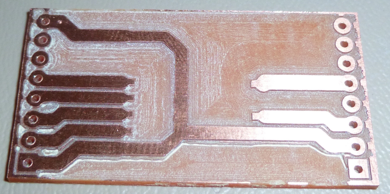
Here's my first attempt at copper removal between the traces/pads:
I used a 2mm endmill to do the work pretty fast. It actually came out pretty good, but the remaining un-removed copper is not what I wanted. I guess it's inevitable unless I use a supper narrow end-mill, or probably a carving bit. But that will take a lot longer.i.e. some kind of hybrid approach would be best, I should think. Is there some way to do the detailed cleanup with a small bit, and then switch to the large diameter bit for the fast cleanup where precision isn't needed?
-
Here's my first attempt at copper removal between the traces/pads:
I used a 2mm endmill to do the work pretty fast. It actually came out pretty good, but the remaining un-removed copper is not what I wanted. I guess it's inevitable unless I use a supper narrow end-mill, or probably a carving bit. But that will take a lot longer.i.e. some kind of hybrid approach would be best, I should think. Is there some way to do the detailed cleanup with a small bit, and then switch to the large diameter bit for the fast cleanup where precision isn't needed?
@neverdie Looks like you could raise your end mill a bit (no pun intended). Shouldn't it be the same depth as your other bit?
Vera Plus running UI7 with MySensors, Sonoffs and 1-Wire devices
Visit my website for more Bits, Bytes and Ramblings from me: http://dan.bemowski.info/ -
@neverdie Looks like you could raise your end mill a bit (no pun intended). Shouldn't it be the same depth as your other bit?
@dbemowsk said in CNC PCB milling:
@neverdie Looks like you could raise your end mill a bit (no pun intended). Shouldn't it be the same depth as your other bit?
In theory, I suppose maybe so. However, the trouble is I can't preserve and then re-apply the same auto-leveling results. And, after the initial isolation milling, I can't do another to support setting the copper removal depth, because the touchpoints might hit the already removed material, which would seriously skew the results. So, I just set it deep enough to cover the possibilities, and that's why it's deeper.
If anyone has a better solution to that, I'm all ears.
-
@neverdie My apologies for near hijacking your thread. I am going to create a new one so I don't mess yours up.
Vera Plus running UI7 with MySensors, Sonoffs and 1-Wire devices
Visit my website for more Bits, Bytes and Ramblings from me: http://dan.bemowski.info/ -
@neverdie My apologies for near hijacking your thread. I am going to create a new one so I don't mess yours up.
-
Answering my own earlier questin, I forgot to remove the PCB coating using IPA before soldering. I think it probably did make the soldering come out a bit funky looking:
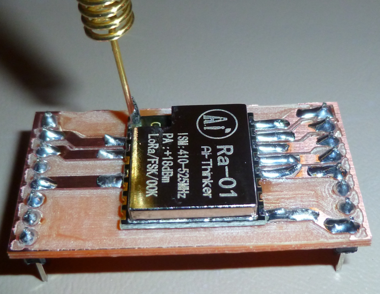
Next time I'll remove it first.Appearances aside, though, it should still work.
-
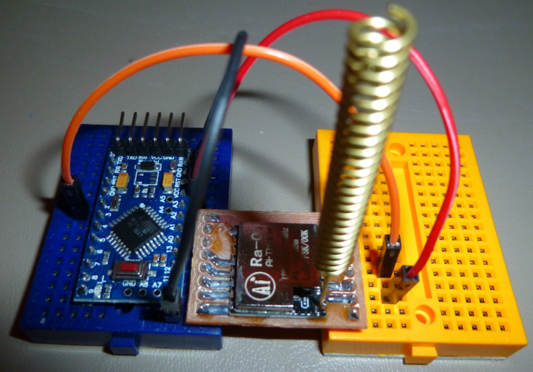
I made the breakout board a bit smaller, and then, since the proof of the pudding is in the taste, I connected it to a pro mini and ran it. Voilà! It works like a charm. :)
-
@andrew What is the widest diameter end-mill bit that this CNC machine can accept and handle? I'm thinking in terms of the mill leveling discussed earlier, and going wide to speed up the process.
@neverdie Pardon my interruption, but I seem to recall my mentioning this near the start of this CNC adventure, and that there was a collet available for that device to accept 8mm standard wood routing bits...
I realise that US traditionally holds to 1/4 and 1/2 inch shafts, but the bigger the size the greater the mass to spin up and motor requirements... Pretty sure you would still be able to find 8mm bits...