CNC PCB milling
-
I suppose, in theory, that somehow replacing the x and z-axis with these might mitigate against the twist problem:
Presumably the rails are precisely spaced and held perfectly flat by the base plate, so you'd avoid binding problems that might otherwise arise from a purely DIY manual retrofit of just the rails.
I don't know what the MGN number is for that rail though, so I don't know whether its MGN15, MGN20, or something else.
-
@neverdie said in CNC PCB milling:
@dbemowsk said in CNC PCB milling:
a dual notched pulley
I don't know what that is.
I wasn't sure of the exact name for it, but I was referring to something like this:
https://www.amazon.com/ReliaBot-Aluminum-Timing-Pulley-Printer/dp/B079JGYYKV/ref=sr_1_5?s=industrial&ie=UTF8&qid=1520378263&sr=1-5&keywords=dual+timing+pulley -
@dbemowsk
I take back what I said earlier. I like the way this guy did it better, because with the gearing you can get even more resolution out of your encoder:
https://youtu.be/wu-1f2CMlmY -
@dbemowsk
I take back what I said earlier. I like the way this guy did it better, because with the gearing you can get even more resolution out of your encoder:
https://youtu.be/wu-1f2CMlmY -
I did some more reading about CNC'ing aluminum, and it's being claimed that virtually any CNC machine can cut aluminum, provided it uses the right depth of cut and speeds and feeds. i.e. it may simply take a lot longer than you would prefer if your machine isn't already super rigid. If that's true, I can probably live with that.
Meanwhile, it has been suggested that using PID might improve things. There's SuperPID for AC powered spindles and I'm not sure what for DC powered spindles. Regardless, I'll need to sense the RPM of the spindle, or it won't work, so that's now on the critical path. I think I'll try a spinning magnet and a hall sensor to sense the RPM.
-
@NeverDie -- the motors used in 1610 CNC mills are generally what are called a "775 Motor". You might be able to find other specs, but the ones I've found suggest that at 24V and no load , they claim 7kRPM -- http://linksprite.com/wiki/index.php5?title=File:Motor_performance_parameter.png; I'm not sure how much slower we could expect it to be while milling. As far as actually measuring this, there are devices you could buy, but you could pretty easily fabricobble your way to an answer if you wanted to make a project out of it: http://www.instructables.com/id/Measure-RPM-DIY-Portable-Digital-Tachometer/.
I have the same mill as you, and swapped for one of these https://www.amazon.com/gp/product/B074FVKRZM/ and have had much better results so far.
@coddingtonbear said in CNC PCB milling:
@NeverDie -- the motors used in 1610 CNC mills are generally what are called a "775 Motor". You might be able to find other specs, but the ones I've found suggest that at 24V and no load , they claim 7kRPM -- http://linksprite.com/wiki/index.php5?title=File:Motor_performance_parameter.png; I'm not sure how much slower we could expect it to be while milling. As far as actually measuring this, there are devices you could buy, but you could pretty easily fabricobble your way to an answer if you wanted to make a project out of it: http://www.instructables.com/id/Measure-RPM-DIY-Portable-Digital-Tachometer/.
I have the same mill as you, and swapped for one of these https://www.amazon.com/gp/product/B074FVKRZM/ and have had much better results so far.
Does the controller that comes with your motor allow you to set the RPM of the motor, or does it just set the voltage? If it knows RPM and can act like a PID (i.e. adapts to maintain the target RPM even under varying loads), then it would be very attractive.
-
I went ahead and orderd the Hall Effect version, which appears to come with some kind of DSP PID controller to control the speed of its DC spindle.
https://www.aliexpress.com/item/Freeshipping-Brushless-spindle-motor-driver-Motor-base-kit-BL-Engraver-Spindle-Motor-24VDC-60VDC-12000RPM-ER8/32849306845.html?spm=2114.search0204.3.72.2cc61acfYE6xkB&ws_ab_test=searchweb0_0,searchweb201602_5_10152_5711320_10151_10065_10344_10068_10130_10324_10342_10547_10325_10343_10546_10340_10548_10341_10545_10084_10083_10618_10307_5711220_5722420_10313_10059_10534_100031_10103_10627_10626_10624_10623_10622_10621_10620,searchweb201603_25,ppcSwitch_5_ppcChannel&algo_expid=7790ac4f-6dbd-47b4-9574-1d713348386c-11&algo_pvid=7790ac4f-6dbd-47b4-9574-1d713348386c&transAbTest=ae803_3&priceBeautifyAB=0 -
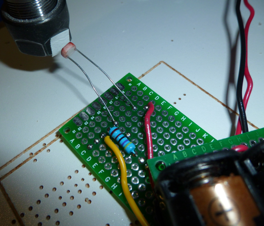
I used a piece of white tape, a photo resistor, and an oscilliscope to measure the RPM on the existing spindle that came with the 2418 kit. Unloaded, it's 8333RPM.
-
I did further tests on my CNC this morning, with interesting results.
First, I confirmed that the motor is, indeed, being powered at 24VDC using pulse width modulation from the WoodPecker. As an experiment, I tried powering it directly from my lab bench power supply at different voltages, and it definitely runs smoother that way rather than relying on PWM.
Second, when I ran it at very low speeds, I could tell visually that the spindle runout was attrocious. I think this is a big contributing factor to vibration, audible noise, and probably tearing in the copper of the PCB. It may be that the large stick-out of the ER11 is a contributing factor.
-
I have a question regarding setup of the CNC. Which directions are the positive directions for all of the axes? For example, if I send "Z10" should the spindle move up or down?
X - left or right?
Y - forward or backward?
Z - Up or down? -
@coddingtonbear said in CNC PCB milling:
@NeverDie -- the motors used in 1610 CNC mills are generally what are called a "775 Motor". You might be able to find other specs, but the ones I've found suggest that at 24V and no load , they claim 7kRPM -- http://linksprite.com/wiki/index.php5?title=File:Motor_performance_parameter.png; I'm not sure how much slower we could expect it to be while milling. As far as actually measuring this, there are devices you could buy, but you could pretty easily fabricobble your way to an answer if you wanted to make a project out of it: http://www.instructables.com/id/Measure-RPM-DIY-Portable-Digital-Tachometer/.
I have the same mill as you, and swapped for one of these https://www.amazon.com/gp/product/B074FVKRZM/ and have had much better results so far.
Does the controller that comes with your motor allow you to set the RPM of the motor, or does it just set the voltage? If it knows RPM and can act like a PID (i.e. adapts to maintain the target RPM even under varying loads), then it would be very attractive.
@neverdie Yes, it does. There are a variety of ways of controlling the one I bought, and you can easily configure which method is in use. I think this one has three different options -- controlling RPM via an analog voltage, controlling RPM via PWM, and controlling RPM via a knob on the controller. I use PWM, but you'll probably always want to be at full speed when milling PCBs, so I'd bet just using the knob would be fine.
-
I went ahead and orderd the Hall Effect version, which appears to come with some kind of DSP PID controller to control the speed of its DC spindle.
https://www.aliexpress.com/item/Freeshipping-Brushless-spindle-motor-driver-Motor-base-kit-BL-Engraver-Spindle-Motor-24VDC-60VDC-12000RPM-ER8/32849306845.html?spm=2114.search0204.3.72.2cc61acfYE6xkB&ws_ab_test=searchweb0_0,searchweb201602_5_10152_5711320_10151_10065_10344_10068_10130_10324_10342_10547_10325_10343_10546_10340_10548_10341_10545_10084_10083_10618_10307_5711220_5722420_10313_10059_10534_100031_10103_10627_10626_10624_10623_10622_10621_10620,searchweb201603_25,ppcSwitch_5_ppcChannel&algo_expid=7790ac4f-6dbd-47b4-9574-1d713348386c-11&algo_pvid=7790ac4f-6dbd-47b4-9574-1d713348386c&transAbTest=ae803_3&priceBeautifyAB=0@neverdie Congratulations on your purchase! I think you'll find having a real spindle will help a ton.
If you haven't designed your own mount, you might want to check out the part I posted on Thingiverse the other day: https://www.thingiverse.com/thing:2817974 .
-
@neverdie Yes, it does. There are a variety of ways of controlling the one I bought, and you can easily configure which method is in use. I think this one has three different options -- controlling RPM via an analog voltage, controlling RPM via PWM, and controlling RPM via a knob on the controller. I use PWM, but you'll probably always want to be at full speed when milling PCBs, so I'd bet just using the knob would be fine.
@coddingtonbear said in CNC PCB milling:
@neverdie Yes, it does. There are a variety of ways of controlling the one I bought, and you can easily configure which method is in use. I think this one has three different options -- controlling RPM via an analog voltage, controlling RPM via PWM, and controlling RPM via a knob on the controller. I use PWM, but you'll probably always want to be at full speed when milling PCBs, so I'd bet just using the knob would be fine.
So, during deeper cuts, the controller responds by giving the spindle more oomph to maintain the specific RPM you set? That's the key question.
-
@neverdie Congratulations on your purchase! I think you'll find having a real spindle will help a ton.
If you haven't designed your own mount, you might want to check out the part I posted on Thingiverse the other day: https://www.thingiverse.com/thing:2817974 .
@coddingtonbear said in CNC PCB milling:
@neverdie Congratulations on your purchase! I think you'll find having a real spindle will help a ton.
If you haven't designed your own mount, you might want to check out the part I posted on Thingiverse the other day: https://www.thingiverse.com/thing:2817974 .
Thanks! That does increase the cantilever effect, but it's a good start. I guess it's even good enough based on your experience so far, which would be awesome. Thanks for sharing.
-
@coddingtonbear said in CNC PCB milling:
@neverdie Yes, it does. There are a variety of ways of controlling the one I bought, and you can easily configure which method is in use. I think this one has three different options -- controlling RPM via an analog voltage, controlling RPM via PWM, and controlling RPM via a knob on the controller. I use PWM, but you'll probably always want to be at full speed when milling PCBs, so I'd bet just using the knob would be fine.
So, during deeper cuts, the controller responds by giving the spindle more oomph to maintain the specific RPM you set? That's the key question.
@neverdie Hrm; honestly I haven't monitored it very closely, and almost always run the spindle at full speed; so I can't really say for sure if it would attempt to adjust to make up for higher friction. Also, I have the NVBDL rather than the NVBDH version, so I'm not even sure if it is able to tell if the motor is spinning slower than intended.
If either of us have a chance of that being a possibility, it's probably you with the slightly better spindle driver.
-
@neverdie Hrm; honestly I haven't monitored it very closely, and almost always run the spindle at full speed; so I can't really say for sure if it would attempt to adjust to make up for higher friction. Also, I have the NVBDL rather than the NVBDH version, so I'm not even sure if it is able to tell if the motor is spinning slower than intended.
If either of us have a chance of that being a possibility, it's probably you with the slightly better spindle driver.
@coddingtonbear Makes sense. I should be able to trap the signal from the hall effect encoder to confirm the RPM using an Arduino, and then I can compare actual against prescribed RPM to see how well they match. But, as you say, it may not matter if the best speed for etching PCB's is simply "as fast as possible." i.e. if 'it's already running at maximum voltage, then there's no headroom left to speed up an overloaded bit.
-
I ordered a 3.175mm ER8 collet for the new spindle so that I can continue using my same bits:
-
The NVBDH+ brushless spindle and controller arrived today, and so I hooked them up to a power supply and gave them a quick test spin. It runs comparatively quiet. The motor itself is pretty much sealed. On the positive side of that, little if any dust will ever get inside it. On (maybe) the negative side, the fan basically directs air at the back of the motor, and not really anywhere else. I’m only guessing, but keeping other parts of it cool may prove challenging if doing a lot of deep cuts on wood, for example.. For milling PCB’s, I don’t think it will be a problem though. It has little, if any, visible run-out, so in that dimension it appears to be far better than the spindle that came with the 2418 kit. :)
I won't be able to test it on the CNC itself until after my 3D printer arrives because it's too large to fit the kit spindle's holding bracket.
-
@neverdie Hrm; honestly I haven't monitored it very closely, and almost always run the spindle at full speed; so I can't really say for sure if it would attempt to adjust to make up for higher friction. Also, I have the NVBDL rather than the NVBDH version, so I'm not even sure if it is able to tell if the motor is spinning slower than intended.
If either of us have a chance of that being a possibility, it's probably you with the slightly better spindle driver.
@coddingtonbear How hot does your motor get when you're using it? I'm concerned that only one end of it seems to be getting blown by the fan, and since it will be held by plastic....
Hello! It looks like you're interested in this conversation, but you don't have an account yet.
Getting fed up of having to scroll through the same posts each visit? When you register for an account, you'll always come back to exactly where you were before, and choose to be notified of new replies (either via email, or push notification). You'll also be able to save bookmarks and upvote posts to show your appreciation to other community members.
With your input, this post could be even better 💗
Register Login