CNC PCB milling
-
@neverdie I never used it to do silkscreening, but years ago I made a few PCBs to try a sheet out. It worked okay. I had some gaps in some traces on some the boards. That may have been from me not cleaning the board well enough before doing the transfer.
-
@executivul said in CNC PCB milling:
@neverdie http://caram.cl/software/flatcam/tracing-the-silkscreen-with-flatcam/
Have you tried it? i.e. Do you know if it works, or is it a blind reference?
@neverdie said in CNC PCB milling:
@executivul said in CNC PCB milling:
@neverdie http://caram.cl/software/flatcam/tracing-the-silkscreen-with-flatcam/
Have you tried it? i.e. Do you know if it works, or is it a blind reference?
I've done it a few times, be careful though you don't cut your traces with the silkscreen :)
I use the tracing option all the time for custom cutouts when panelising boards, generate cutout paths in Altium and trace in Flatcam. -
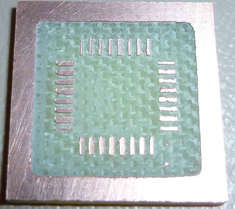
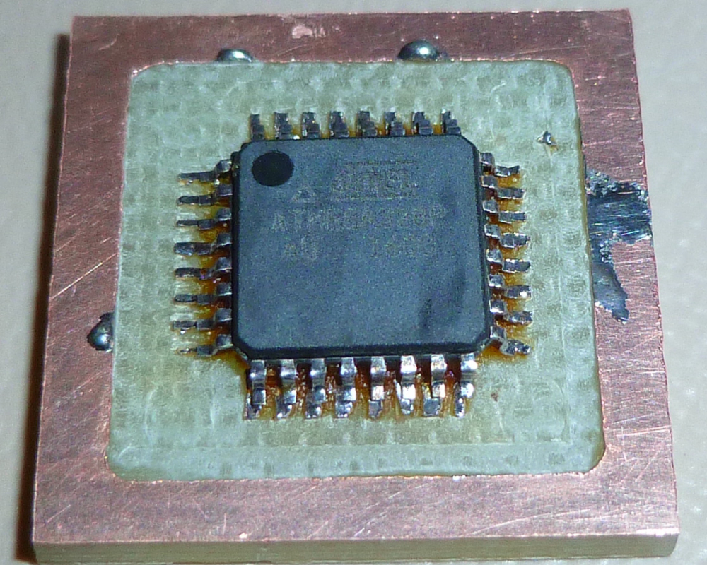
My Prusa i3 Mk3 still hasn't shipped due to production delays, and so I haven't been able to mount the new spindle yet on my PCB etching mill. Meanwhile, it looks as though the existing setup may just barely be good enough for etching pads for the atmega328p SMD. By using lots of rosin flux, it looks like I can solder to it without unresolvable solder bridges.
-
Also, I received a TMC2130 stepper driver, so I'll be auditioning that fairly soon:
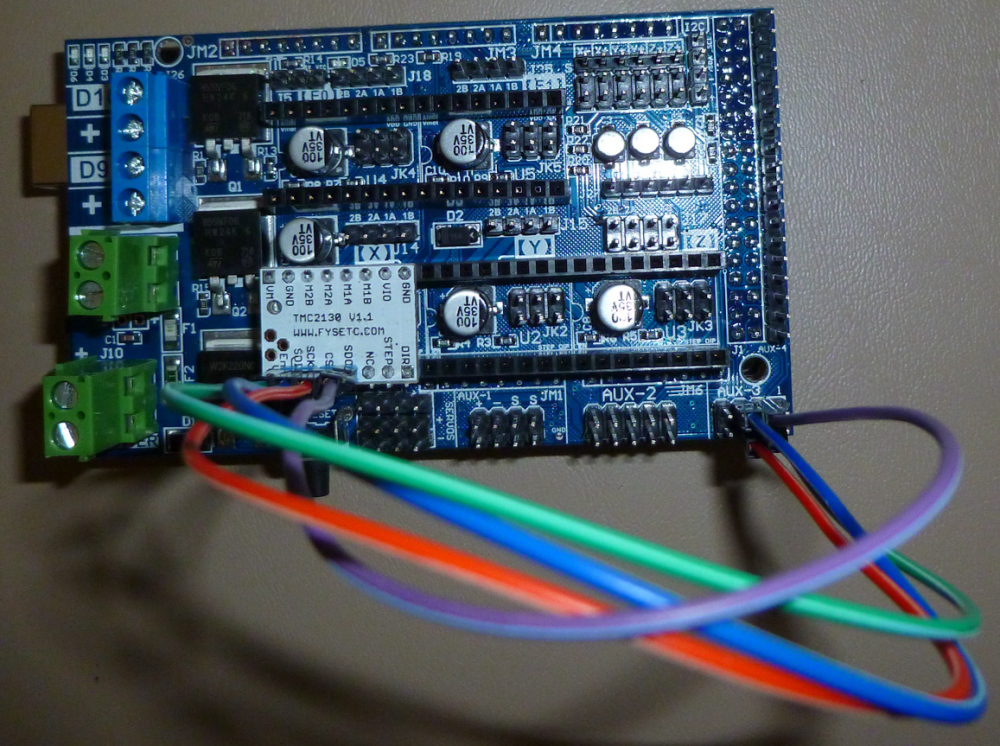
Supposedly it is a bit more precise, and so that may help also. If it pans out, then I'll order TMC2130's for the Y and Z axis also. -
My Prusa i3 Mk3 still hasn't shipped due to production delays, and so I haven't been able to mount the new spindle yet on my PCB etching mill. Meanwhile, it looks as though the existing setup may just barely be good enough for etching pads for the atmega328p SMD. By using lots of rosin flux, it looks like I can solder to it without unresolvable solder bridges.
@neverdie Here is an interesting approach that might work, but it requires etching.
https://www.youtube.com/watch?v=sNh0ubRcTYUVera Plus running UI7 with MySensors, Sonoffs and 1-Wire devices
Visit my website for more Bits, Bytes and Ramblings from me: http://dan.bemowski.info/ -
@neverdie Here is an interesting approach that might work, but it requires etching.
https://www.youtube.com/watch?v=sNh0ubRcTYU@dbemowsk Using a laser is another way:
https://www.youtube.com/watch?v=gm5P74vcB84 -
Good news! This guy has identified what may be the ultimate stepper motor driver for CNC:
https://www.youtube.com/watch?v=p4ltHDpxrbIAnd he says that by pairing it with your own mosfets, you can send up to 20amps to your stepper motor. Taken altogether, this sounds like a really good setup to me. :)
I assume that with this gear you can just tell the motor to go at maximum speed all the time and let it decide (through monitoring) what that speed should be. No more underperformance or endless tuning of parameters.
-
@neverdie Congratulations on your purchase! I think you'll find having a real spindle will help a ton.
If you haven't designed your own mount, you might want to check out the part I posted on Thingiverse the other day: https://www.thingiverse.com/thing:2817974 .
@coddingtonbear said in CNC PCB milling:
If you haven't designed your own mount, you might want to check out the part I posted on Thingiverse the other day: https://www.thingiverse.com/thing:2817974 .
I'm finally able to print this. Is 20% infill OK, or does it need to be completely solid?
-
@coddingtonbear said in CNC PCB milling:
If you haven't designed your own mount, you might want to check out the part I posted on Thingiverse the other day: https://www.thingiverse.com/thing:2817974 .
I'm finally able to print this. Is 20% infill OK, or does it need to be completely solid?
-
I blithely printed the parts using PLA. Now I need to find a strong glue to weld the braces into place. Anyone know of a strong glue that works well with PLA?
@neverdie Answering my own question, it appears (according to this Hackaday article: https://hackaday.com/2018/02/07/locally-sourced-pla-adhesive/) that weldon #16 will do the business in terms of solvent welding PLA.
-
Comparing my spindle mount:
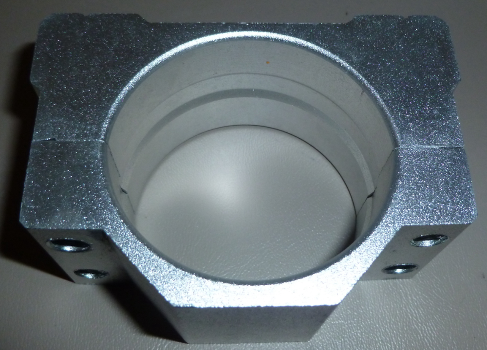
to Coddingtonbear's 55mm spindle mount:
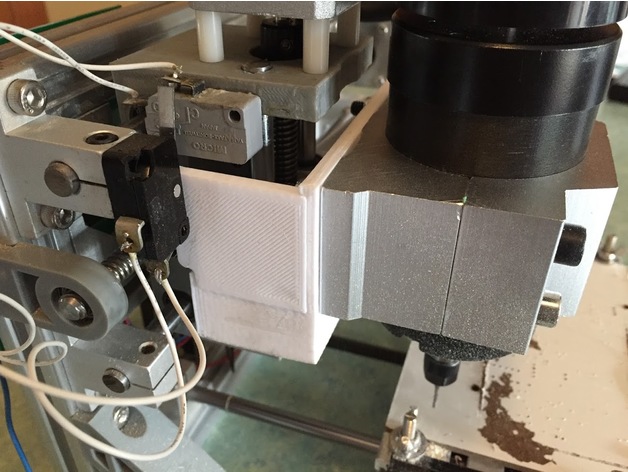
it seems that mine is intended for a 52mm spindle. Unfortunately, I'll just have to make do, as nobody that I can find seems to be selling standalone true 55mm spindle mounts, like Coddingtonbear has.Fortunately, though, the holes on mine do align with the holes on Coddingtonbear's 3D printed adapter. :)
-
I upgraded to the brushless motor after 3D printing cottingbear's adapter. Then I ran @executivul 's test scripts to check its performance. It looks as though the new spindel can support faster feedrates, but the trace isolation is 0.7mm, which is much larger than the original cheapo spindle. :( It has an ER8 on it, not an ER11. Not sure if that's to blame (?). I wouldn't think so, though, because I'm using a 1.75mm collet on it.
The z-axis still has a lot of flex in it. I think that's probably a factor. I'm not sure what can be done to mod my way out of that. Perhaps I'd be better off getting a proper CNC mill rather than this wobbly type of design.
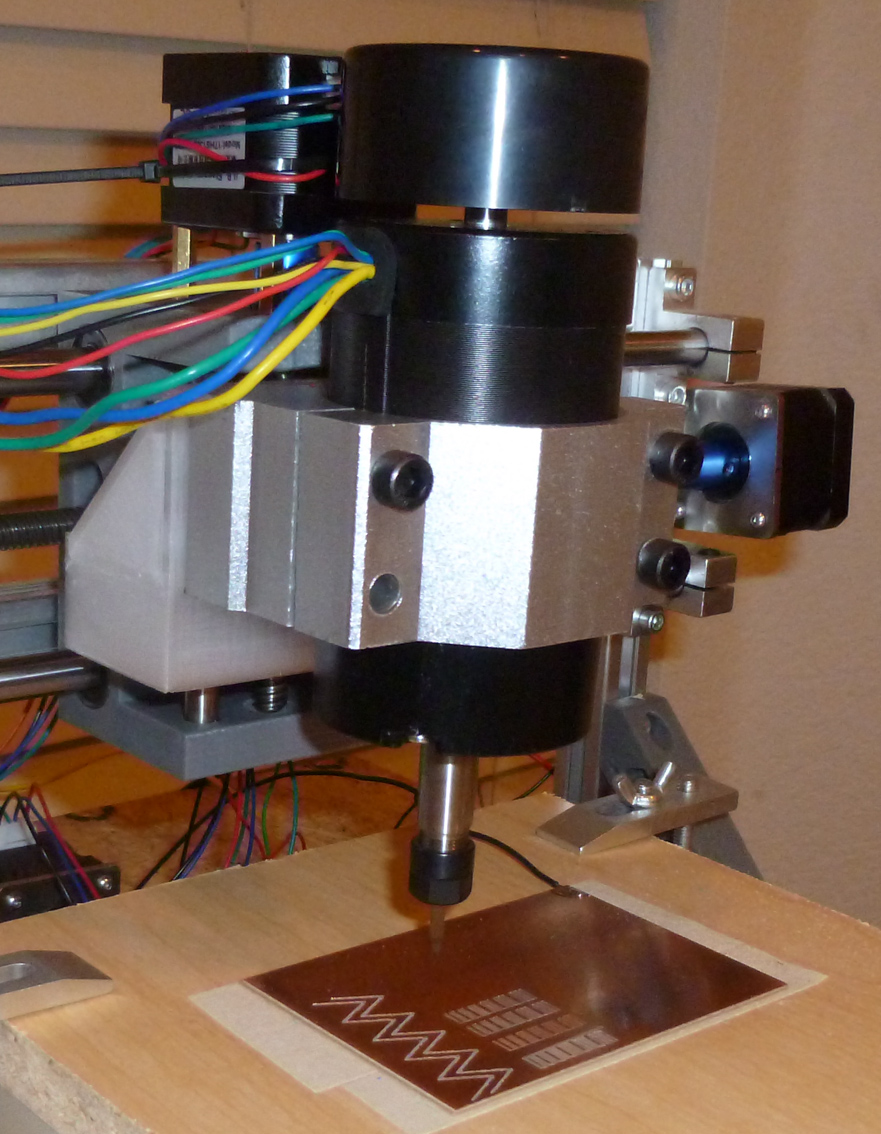
I can now see the advantage of having two z-axis motors, one on each side of the spindle. That would probably give it at least a bit more rigidity. Either that, or a single very rigid,, unmoving central column as used by mills.
-
Any suggestions on how to improve it?
-
I upgraded to the brushless motor after 3D printing cottingbear's adapter. Then I ran @executivul 's test scripts to check its performance. It looks as though the new spindel can support faster feedrates, but the trace isolation is 0.7mm, which is much larger than the original cheapo spindle. :( It has an ER8 on it, not an ER11. Not sure if that's to blame (?). I wouldn't think so, though, because I'm using a 1.75mm collet on it.
The z-axis still has a lot of flex in it. I think that's probably a factor. I'm not sure what can be done to mod my way out of that. Perhaps I'd be better off getting a proper CNC mill rather than this wobbly type of design.
I can now see the advantage of having two z-axis motors, one on each side of the spindle. That would probably give it at least a bit more rigidity. Either that, or a single very rigid,, unmoving central column as used by mills.
-
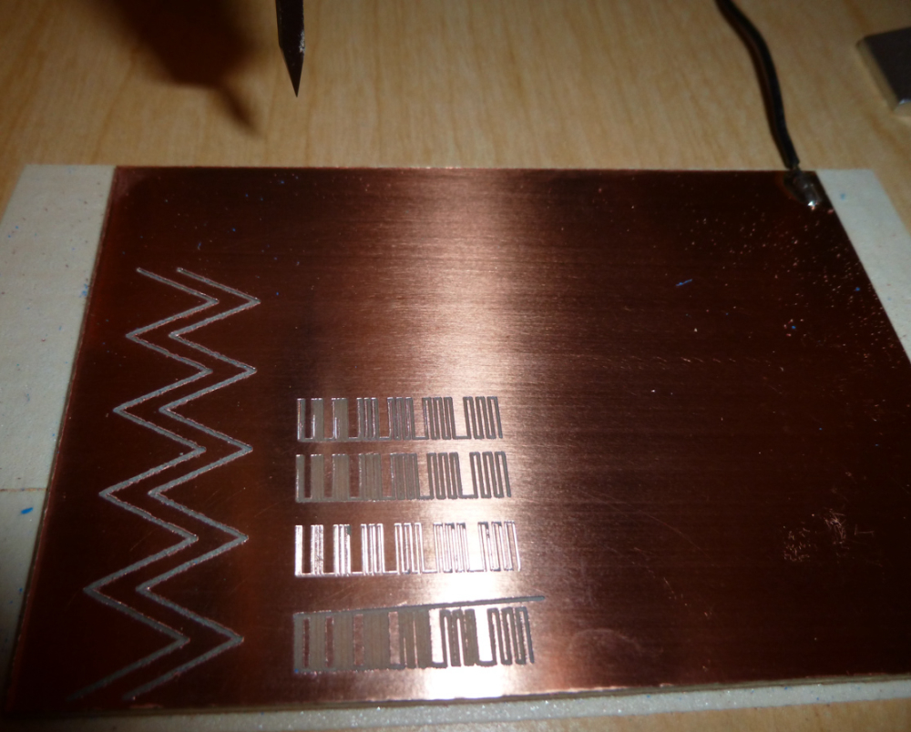
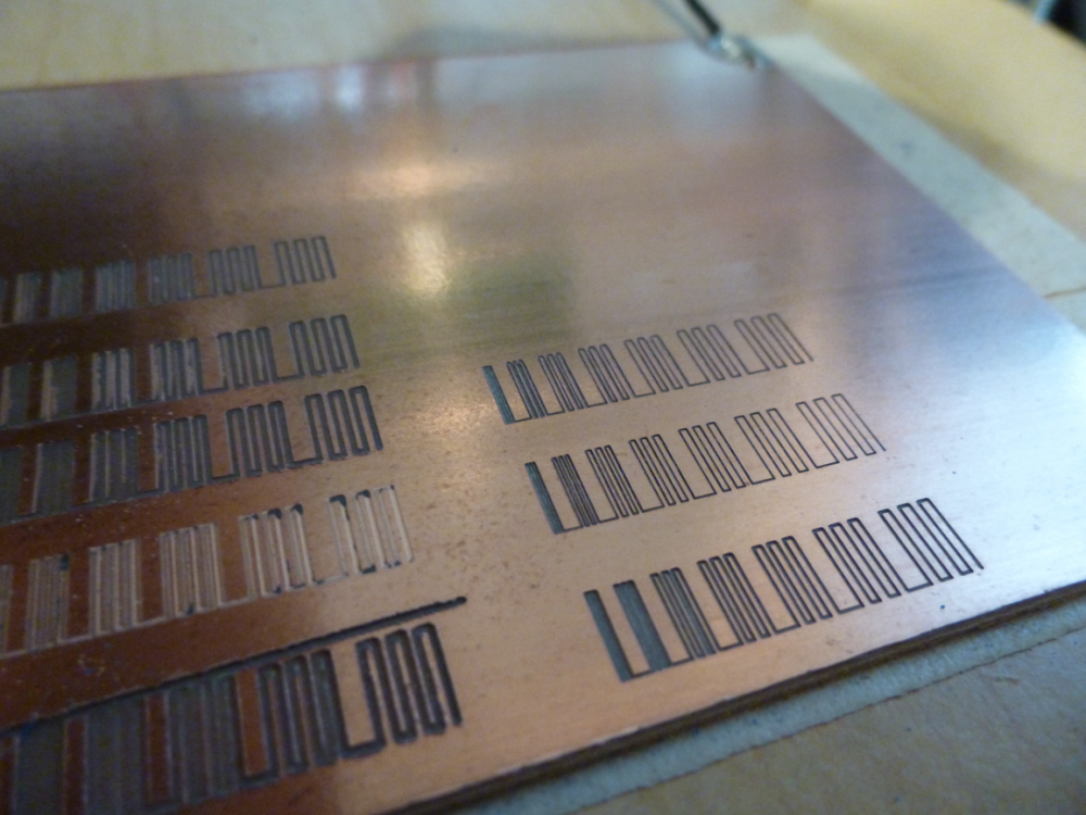
I switched to a 52mm spindle, and now I'm getting better results:
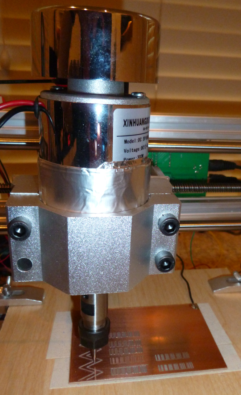
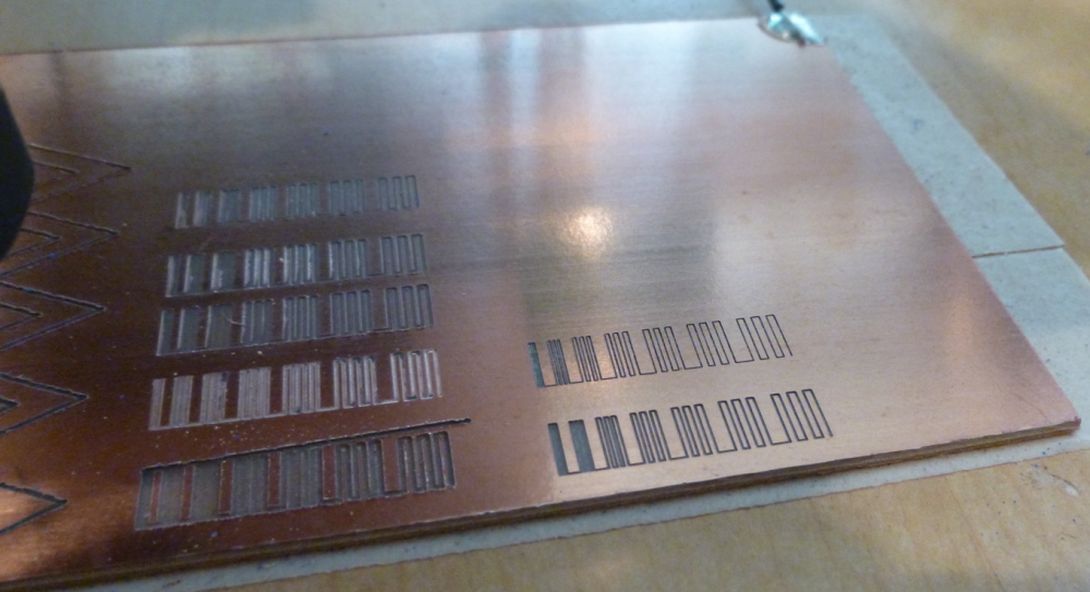
The benchmarks on the right were produced by the 52mm spindle. :) Those on the left by the 54mm brushless spindle. -
I switched to a 52mm spindle, and now I'm getting better results:
The benchmarks on the right were produced by the 52mm spindle. :) Those on the left by the 54mm brushless spindle.@neverdie I guess some backlash being present. Is the brushless heavier than the other one?
The width of the cut is proportional to engraving bit tip size, depth of cut, tip angle, the spindle itself should be irrelevant except runout, of course, but you will hear the runout long before you see it, a 0.1mm of runout will make a hell lot of noise and rattling.
For greater rpms er8 is better than er11, my 60k rpm has er8 the 24k have er11.
Try to find the highers resonance pole rpm, turn the rpm to max, slowly decrease it while listening carefully, take a note when it's quieter, use the highest rpm that runs quietly. This setting unfortunately changes with every tool change, sometimes you won't have a good enough rpm resonant pole so you take out the bit, nut and collet and reassemble. By turning them you change the invisible runout a bit and you get another system state. On my spindle every 1/10-1/15 tool changes results in heavy resonance and I must proceed as above. -
@neverdie I guess some backlash being present. Is the brushless heavier than the other one?
The width of the cut is proportional to engraving bit tip size, depth of cut, tip angle, the spindle itself should be irrelevant except runout, of course, but you will hear the runout long before you see it, a 0.1mm of runout will make a hell lot of noise and rattling.
For greater rpms er8 is better than er11, my 60k rpm has er8 the 24k have er11.
Try to find the highers resonance pole rpm, turn the rpm to max, slowly decrease it while listening carefully, take a note when it's quieter, use the highest rpm that runs quietly. This setting unfortunately changes with every tool change, sometimes you won't have a good enough rpm resonant pole so you take out the bit, nut and collet and reassemble. By turning them you change the invisible runout a bit and you get another system state. On my spindle every 1/10-1/15 tool changes results in heavy resonance and I must proceed as above.@executivul Cool! Here's my first attempt at that, and it's already producing a visibly different result:
As to which spindle is heavier, I don't know. The next time I demount the brush spindle, I'll weigh it and let you know.
Thanks!
-
This guy developed his own method for balancing the high speed motors used on his quadcopter. I can't help but think that maybe something similar could be done on a CNC spindle.
https://www.youtube.com/watch?v=RItntpZZH4g&t=747s -
And these guys have the same idea, but they instead use a laser to visualize the magnitude of the vibration:
https://www.youtube.com/watch?v=PqtUSSdf8b4