GUIDE - NRF5 / NRF51 / NRF52 for beginners


  • @Nca78 I feared that might be the case. my task for today was to dig up my st-link and try that, though I hoped I might have done something wrong and the cp2102 can be used to program and not just debug.
    That module is pretty cheap and from what I see with the naked eye, you can disconnect the cp2102 with the jumpers so the power consumption might actually be good enough to use as-is.
    I'll report back to let you know once I've succeeded


  • I tried flashing MySensors onto my nRF52840 Adafruit Feather board but it fails, I opened an issue on GH about it https://github.com/mysensors/MySensors/issues/1424, maybe someone here has any ideas how to get it running on those boards?


  • @Nca78 no luck with the st-link v2, though i doubt it is related to the board, but rather my inability. i've tried every option in zadig, installed the st-link driver from their website, and nothing works.
    i get this in arduino ide:

    debug_level: 0
    0x4000
    adapter speed: 10000 kHz
    Error: init mode failed (unable to connect to the target)
    in procedure 'program' 
    in procedure 'init' called at file "embedded:startup.tcl", line 473
    in procedure 'ocd_bouncer'
    ** OpenOCD init failed **
    shutdown command invoked
    
    the selected serial port 
     does not exist or your board is not connected


  • With all the NRF52 modules from EBYTE I've tried, the only way I can flash them is over SWDIO, SWCLK, GND, VCC via JLink clone.

    And, before flashing is possible, I have to unlock the module by following these directions: https://github.com/micooke/arduino-nRF5-smartwatches/blob/master/nrf52_disable_read_protection.txt


  • @ncollins I've been working on turning an stm32f030f4p6 into a blackmagic probe for a few days now. Hit a wall when the compiled firmware came out to 83kb which is over the 64kb on board. Found someone who shrunk it down so it'd fit, and someone claiming it has another 64kb which can be unlocked. I'm just looking for the patience to get back in there, as this whole thing has been a major ordeal


  • Im not sure my flashing with the blackmagic even does anything. The console is unclear:

    Sketch uses 3556 bytes (0%) of program storage space. Maximum is 409600 bytes.
    Remote debugging using \\.\COM11
    Target voltage: ABSENT!
    Available Targets:
    No. Att Driver
     1      Nordic nRF52 M3/M4
     2      Nordic nRF52 Access Port 
    Attaching to Remote target
    0xfffffffe in ?? ()
    Reading symbols from nrf1.ino.elf...done.
    Loading section .text, size 0xde4 lma 0x1c000
    Loading section .ARM.exidx, size 0x8 lma 0x1cde4
    Loading section .data, size 0x78 lma 0x1cdec
    Start address 0x1c578, load size 3684
    Transfer rate: 33 KB/sec, 614 bytes/write.
    Temporary breakpoint 1 at 0x1cb8c: file C:\Users\....\AppData\Local\Arduino15\packages\sandeepmistry\hardware\nRF5\0.6.0\cores\nRF5\main.cpp, line 28.
    Starting program: C:\Users\....\AppData\Local\Temp\arduino_build_366086\nrf1.ino.elf 
    Note: automatically using hardware breakpoints for read-only addresses.
    
    Program received signal SIGSEGV, Segmentation fault.
    0x00000000 in ?? ()
    
    Program complete!
    

    and i dont see any serial debug information


  • I just got my first NRF5 running. I'll note how I got it working in case any of you guys still have troubles:

    Setup

    • OS: Windows 10
    • Programmer: STM32 Blue Pill with the Black Magic Probe firmware
    • NRF5: EByte E73-TBB dev board with a E73-2G4M0S1B (NRF52832)
    • Environment: PlatformIO

    Instructions

    Load the Black Magic Probe firmware with stlink as the probe host onto Blue Pill. You can follow this guide.

    Connect your new BMP to the NRF52 module:

    BMP NRF52 Serial Port
    3V3 3V3
    GND GND
    A5 SWDCLK GDB Server
    B14 SWDIO GBD Server
    A2 RXI UART
    A3 TXO UART

    Note: A2 and A3 are not required for programming. This is how you'd wire up the BMP for "classic" serial debugging. You can use the BMP both for programming and serial communication - no need for a second FTDI module.

    Using the GNU Arm Embedded Toolchain, run arm-none-eabi-gdb in a console and enter the following commands to unlock the NRF52:

    target extended-remote BMP_GDB_SERVER_PORT
    mon swdp_scan
    attach N // N = number of "Nordic nRF52 Access Port" if there are several
    mon erase_mass
    detach
    

    From the two serial ports the BMP provides, you want to use the GDB Server for BMP_GDB_SERVER_PORT above. If Windows only provides generic names for both ("USB Serial Device" or something), the one with the lower number should (usually) be the right choice. If not, try the other one.

    Windows users also must prefix the port with \\.\ if the number is double-digit, e.g. \\.\COM13.

    Now you can start uploading sketches the usual way. Here's my minimal PlatformIO config:

    [env:nrf52_dk]
    platform = nordicnrf52
    board = nrf52_dk
    board_build.variant = generic
    framework = arduino
    upload_protocol = blackmagic
    lib_deps = 
    	548 ; MySensors
    

    And a minimal test sketch for MySensors:

    #include <Arduino.h>
    
    #define LED 17
    
    #define MY_RADIO_RF24
    #define MY_RADIO_NRF5_ESB
    #define MY_NODE_ID 182
    
    #define SKETCH_NAME "NRF52 Test"
    #define SKETCH_VERSION "0.1"
    
    #include <MySensors.h>
    
    #define CHILD_ID 1
    MyMessage msg(CHILD_ID, V_VAR1);
    
    void presentation()
    {
      sendSketchInfo(SKETCH_NAME, SKETCH_VERSION);
      present(CHILD_ID, S_CUSTOM);
    }
    
    void setup()
    {
      pinMode(LED, OUTPUT);
    }
    
    void loop()
    {
      static uint8_t num;
      send(msg.set(num));
      ++num;
      
      digitalWrite(LED, HIGH);
      wait(5000);
      digitalWrite(LED, LOW);
      wait(5000);
    }
    

    Works like a charm so far! Now, if you please excuse me, I have a whole new microprocessor family to explore. Fun times!


  • @BearWithBeard said in GUIDE - NRF5 / NRF51 / NRF52 for beginners:

    From the two ports the BMP provides, you want to use the GDB Server. If Windows only provides generic names for both ("USB Serial Device" or something), the one with the lower number should be the right choice.

    Strangely, my BMP uses the higher port number as the GDB server and the lower one as the serial port. I think this is unusual since it is opposite of what most guides say to expect. So, try the higher one if the lower one doesn't work.


  • @BearWithBeard said in GUIDE - NRF5 / NRF51 / NRF52 for beginners:

    I just got my first NRF5 running. I'll note how I got it working in case any of you guys still have troubles:

    Setup

    • OS: Windows 10
    • Programmer: STM32 Blue Pill with the Black Magic Probe firmware
    • NRF5: EByte E73-TBB dev board with a E73-2G4M0S1B (NRF52832)
    • Environment: PlatformIO

    Instructions

    Load the Black Magic Probe firmware with stlink as the probe host onto Blue Pill. You can follow this guide.

    Connect your new BMP to the NRF52 module:

    BMP NRF52 Serial Port
    3V3 3V3
    GND GND
    A5 SWDCLK GDB Server
    B14 SWDIO GBD Server
    A2 TX UART
    A3 RX UART

    Note: A2 and A3 are not required for programming. This is how you'd wire up the BMP for "classic" serial debugging. You can use the BMP both for programming and serial communication - no need for a second FTDI module.

    Using the GNU Arm Embedded Toolchain, run arm-none-eabi-gdb in a console and enter the following commands to unlock the NRF52:

    target extended-remote BMP_GDB_SERVER_PORT
    mon swdp_scan
    attach N // N = number of "Nordic nRF52 Access Port" if there are several
    mon erase_mass
    detach
    

    From the two serial ports the BMP provides, you want to use the GDB Server for BMP_GDB_SERVER_PORT above. If Windows only provides generic names for both ("USB Serial Device" or something), the one with the lower number should (usually) be the right choice. If not, try the other one.

    Windows users also must prefix the port with \\.\ if the number is double-digit, e.g. \\.\COM13.

    Now you can start uploading sketches the usual way. Here's my minimal PlatformIO config:

    [env:nrf52_dk]
    platform = nordicnrf52
    board = nrf52_dk
    board_build.variant = generic
    framework = arduino
    upload_protocol = blackmagic
    lib_deps = 
    	548 ; MySensors
    

    And a minimal test sketch for MySensors:

    #include <Arduino.h>
    
    #define LED 17
    
    #define MY_RADIO_RF24
    #define MY_RADIO_NRF5_ESB
    #define MY_NODE_ID 182
    
    #define SKETCH_NAME "NRF52 Test"
    #define SKETCH_VERSION "0.1"
    
    #include <MySensors.h>
    
    #define CHILD_ID 1
    MyMessage msg(CHILD_ID, V_VAR1);
    
    void presentation()
    {
      sendSketchInfo(SKETCH_NAME, SKETCH_VERSION);
      present(CHILD_ID, S_CUSTOM);
    }
    
    void setup()
    {
      pinMode(LED, OUTPUT);
    }
    
    void loop()
    {
      static uint8_t num;
      send(msg.set(num));
      ++num;
      
      digitalWrite(LED, HIGH);
      wait(5000);
      digitalWrite(LED, LOW);
      wait(5000);
    }
    

    Works like a charm so far! Now, if you please excuse me, I have a whole new microprocessor family to explore. Fun times!

    @BearWithBeard just thanks, this method just work fine.
    But just need to use the hightest port number of the BMP.


  • Hardware Contributor

    @idanronen said in GUIDE - NRF5 / NRF51 / NRF52 for beginners:

    Does anyone know what settings I need to use for this development board with arduino ide?
    Ebyte E104-BT5032A-TB
    https://a.aliexpress.com/_dT5dMb8

    It has a cp2102 on board which I have the driver for. I've installed the arduino ide nrf52 board, but I can't find a programmer, board, or any other settings which will let me flash it without a Java exception or a timeout. Maybe I need to set the jumpers differently but there's no documentation on that.
    OTA works fine though.

    So, I have finally received mines, and I can program the SoftDevice on them using NRF52 DK and nRF Go Studio. The first time it tells be there is a readback protection and offers a "Recover" option that erases the chip and allows to use it as normal.
    Now I'll try to see what IOs the MOD, WKP, DISC, LINK, DATA, RX, TX, RTS, CTS pins are connected to and that will make a nice little module for modules with limited space and low io pins requirements.
    Great replacement for NRF51822-04 imho: similar surface, better chip, more IOs and similar low price.


  • @BearWithBeard said in GUIDE - NRF5 / NRF51 / NRF52 for beginners:

    I just got my first NRF5 running. I'll note how I got it working in case any of you guys still have troubles:

    Setup

    • OS: Windows 10
    • Programmer: STM32 Blue Pill with the Black Magic Probe firmware
    • NRF5: EByte E73-TBB dev board with a E73-2G4M0S1B (NRF52832)
    • Environment: PlatformIO

    Instructions

    Load the Black Magic Probe firmware with stlink as the probe host onto Blue Pill. You can follow this guide.

    Connect your new BMP to the NRF52 module:

    BMP NRF52 Serial Port
    3V3 3V3
    GND GND
    A5 SWDCLK GDB Server
    B14 SWDIO GBD Server
    A2 TX UART
    A3 RX UART

    Note: A2 and A3 are not required for programming. This is how you'd wire up the BMP for "classic" serial debugging. You can use the BMP both for programming and serial communication - no need for a second FTDI module.

    Using the GNU Arm Embedded Toolchain, run arm-none-eabi-gdb in a console and enter the following commands to unlock the NRF52:

    target extended-remote BMP_GDB_SERVER_PORT
    mon swdp_scan
    attach N // N = number of "Nordic nRF52 Access Port" if there are several
    mon erase_mass
    detach
    

    From the two serial ports the BMP provides, you want to use the GDB Server for BMP_GDB_SERVER_PORT above. If Windows only provides generic names for both ("USB Serial Device" or something), the one with the lower number should (usually) be the right choice. If not, try the other one.

    Windows users also must prefix the port with \\.\ if the number is double-digit, e.g. \\.\COM13.

    Now you can start uploading sketches the usual way. Here's my minimal PlatformIO config:

    [env:nrf52_dk]
    platform = nordicnrf52
    board = nrf52_dk
    board_build.variant = generic
    framework = arduino
    upload_protocol = blackmagic
    lib_deps = 
    	548 ; MySensors
    

    And a minimal test sketch for MySensors:

    #include <Arduino.h>
    
    #define LED 17
    
    #define MY_RADIO_RF24
    #define MY_RADIO_NRF5_ESB
    #define MY_NODE_ID 182
    
    #define SKETCH_NAME "NRF52 Test"
    #define SKETCH_VERSION "0.1"
    
    #include <MySensors.h>
    
    #define CHILD_ID 1
    MyMessage msg(CHILD_ID, V_VAR1);
    
    void presentation()
    {
      sendSketchInfo(SKETCH_NAME, SKETCH_VERSION);
      present(CHILD_ID, S_CUSTOM);
    }
    
    void setup()
    {
      pinMode(LED, OUTPUT);
    }
    
    void loop()
    {
      static uint8_t num;
      send(msg.set(num));
      ++num;
      
      digitalWrite(LED, HIGH);
      wait(5000);
      digitalWrite(LED, LOW);
      wait(5000);
    }
    

    Works like a charm so far! Now, if you please excuse me, I have a whole new microprocessor family to explore. Fun times!

    For the life of me i cant figure out if im making the BlackMagic properly. I'm moving the boot0 jumper to 1, flashing the 8kb maple (usb flash) DFU file using the st-link application on windows.
    I move the jumper back to 0, and connect using the micro usb, and i can flash code normally using arudino IDE using the STM32duino bootloader (and if i do so, i see the device communication on a new COM port).
    From there i cant get anything from these guides to work. the windows STM "flash demonstrator" app doesnt recognize the device, and i dont have a linux machine available at the moment for the dfu-util (and Ubuntu shell on windows wont recognize the usb device). When i try to flash the blackmagic.bin starting at 0x08002000 using the ST-link software it shows it succeeded, but when i return the jumper to 0 and reset the device, this is what i get:
    3fca00ad-a84e-477a-aaed-c70d4553adc8-image.png
    The 2 new COM ports appear (COM12,COM13), but i cant seem to flash anything successfully.
    I've installed the GNU arm toolchain for windows and tried "target extended-remote \.\COM13" (12 just gets stuck on nothing), and i get:
    f2dd9bb6-d333-41a8-b883-b3ba4a97d25f-image.png


  • @idanronen , I am not an expert but did manage to accomplish what you are doing about a year ago. I can tell you that you are supposed to get two com ports from BMP. Also, where your screen shot says "SW-DP scan failed" means BMP cannot find any 'targets' on the nrf52. You should get back something that looks like this from the scan:
    Available Targets:
    No. Att Driver
    1 ARM Cortex-M
    2 Nordic nRF52 Access Port

    I performed this operation on ~10 nrf52832 and only one failed the scan. I never found out how to solve it.

    Also, your use of the attach command is incorrect. You appear to be trying to attach the com port 13. If the swdp_scan had worked corrrectly, you would then attach the target that shows up in the scan. In my example output, it would be "attach 2" - the nRF52 Access Port.

    That adds what I know, hope it helps a bit.


  • Hello, I'm using MySensors for some years now and after using the NRF24 and recently the RFM69 I want to explore the NRF5 platform.
    My idea is to use a NRF52840 as gateway, and NRF52832 as nodes. So I am making a list so I can get started, but was wondering what else I should order besides the NRF5's?
    I read a programmer is required, for example. What is your experience or advice for this? A ST-link or J-link? Could you share your experiences?
    Thanks
    Rik


  • @electrik I believe NRF52832 and 51822 are the only supported NRF modules at this time. Some people have experimented and modified dependent libraries to get NRF52840 to work with MySensors but I'm not sure it's completely working and definitely wouldn't start there.

    Personally, I like using the Ebyte NRF24 PA+LNA modules for my gateways and repeaters and use the NRF5 modules for end nodes.

    I'm not even sure you can use NRF5 as a radio for a gateway, if so it might only work as a serial gateway.

    As for additional items, I bought a jlink clone after having trouble unlocking ebyte modules with a STLink. Then my jlink clone caused issues (old firmware, not updatable) so I ended up buying a real JLink-edu.

    Other things worth noting: there are a surprising number of hardware bugs with the NRF chips that mostly result in higher power consumption. General advice would be to stay away from NRF51822. EBYTE modules have been consistently reliable, high quality.


  • @ncollins It is possible to use NRF51822 for gateways with serial. I am using it for many months now. We need USB to serial adapter.
    Also, I do not use JLink or ST-Link for flashing the NRF51 chips. I use raspberry pi with OpenOCD.
    OpenOCD setup can be overwhelming (it was for me) but I have been able to make it work and replicate for a while now. If someone needs inputs, I am happy to help. Ask here or reach out to me on discord @ Puneit#2433

    For the very reason you stated - hardware bugs in NR51 chips leading to high power-consumption - they make compact repeater nodes / powered nodes with repeaters.


  • Mentioned hardware bugs are easily omitted by using custom sleep function.


  • @monte Could you please share the custom sleep function?


  • Is it possible to use such a ready made device, and reprogram it with a mysensors sketch?

    https://a.aliexpress.com/_v4kOXD


  • @electrik yes. You will need an SWD programmer, J-link, ST-link or black magic probe will do. But the thing, you've linked isn't NRF5 device. So if you are asking about exactly that device, then answer is no. Only Nordic bluetooth devices are supported by mysensors. The one you've linked uses TI chip.


  • Hi @electrik

    You can program these ibeacons to work with MySensors.
    I reprogrammed one by soldering some wires to a jlink adapter. Not elegant, but it worked.
    Some type of push pin setup would be good if you are going to actually use these modules.

    e38e65ec-0a12-4625-b48c-a16a312f33a0-image.png

    The version I got had only a button on the board, and no way to easily add any other sensors, so they weren't very useful. It would be interesting to try the ones with the temperature and acceleromator.


  • I am using a generic nRF52 dev board with the Arduino nRF52 core. I am trying to get a sample BLE service to display, but it cannot find it on my BLE scanner. After I couldn't get that to work, I decided to make the code even simpler. Since the dev board that I am using has a serial USB out I thought I would just check if I could get a "Hello World!" to the serial monitor... After flashing the soft device, I still couldn't get any output on my serial monitor.

    Open On-Chip Debugger 0.10.0-dev-00254-g696fc0a (2016-04-10-10:13)
    Licensed under GNU GPL v2
    For bug reports, read
    	http://openocd.org/doc/doxygen/bugs.html
    debug_level: 0
    0x4000
    adapter speed: 10000 kHz
    nrf52.cpu: target state: halted
    target halted due to debug-request, current mode: Thread 
    xPSR: 0x61000000 pc: 0x0001b08e msp: 0x20001188
    nrf52.cpu: target state: halted
    target halted due to debug-request, current mode: Thread 
    xPSR: 0x01000000 pc: 0xfffffffe msp: 0xfffffffc
    ** Programming Started **
    auto erase enabled
    nrf52.cpu: target state: halted
    target halted due to breakpoint, current mode: Thread 
    xPSR: 0x61000000 pc: 0x2000001e msp: 0xfffffffc
    wrote 114688 bytes from file C:\Users\Admin\Documents\ArduinoData\packages\sandeepmistry\hardware\nRF5\0.7.0/cores/nRF5/SDK/components/softdevice/s132/hex/s132_nrf52_2.0.1_softdevice.hex in 2.559271s (43.762 KiB/s)
    ** Programming Finished **
    ** Verify Started **
    nrf52.cpu: target state: halted
    target halted due to breakpoint, current mode: Thread 
    xPSR: 0x61000000 pc: 0x2000002e msp: 0xfffffffc
    nrf52.cpu: target state: halted
    target halted due to breakpoint, current mode: Thread 
    xPSR: 0x61000000 pc: 0x2000002e msp: 0xfffffffc
    verified 110636 bytes in 0.372659s (289.924 KiB/s)
    ** Verified OK **
    ** Resetting Target **
    shutdown command invoked
    

    I am using OpenOCD and an ST-Link v2 to upload my code and it looks like it is uploading successfully. Here is the output when I try to flash the S132 soft device:

    void setup() {
      Serial.begin(9600);
      Serial.println("Starting...");
    
    }
    
    void loop() {
      Serial.println("Hello World!");
      delay(1000);
    
    }
    

    I also tried running this code with the MySensors library:

    #define MY_RADIO_NRF5_ESB
    #include <MySensors.h>
    
    void setup() {
      Serial.begin(9600);
      Serial.println("Starting");
    }
    
    void loop() {
      Serial.println("Hello World!");
      delay(3000);
    }
    

    And got this error:

    In file included from C:\Users\Admin\Documents\ArduinoData\packages\sandeepmistry\hardware\nRF5\0.7.0\cores\nRF5/Arduino.h:5:0,
                     from sketch\MyBoardNRF5.ino.cpp:1:
    c:\users\admin\documents\arduinodata\packages\sandeepmistry\tools\gcc-arm-none-eabi\5_2-2015q4\lib\gcc\arm-none-eabi\5.2.1\include\stdint.h:9:26: fatal error: stdint.h: No such file or directory
    compilation terminated.
    exit status 1
    Error compiling for board MyBoardNRF5 nRF52832.
    Error while flashing SoftDevice.
    java.io.FileNotFoundException: C:\Users\Admin\Documents\ArduinoData\packages\MySensors\hardware\nRF5\0.3.0\softdevices.txt (The system cannot find the file specified)


  • @abelson first you have to flash SD and then chose softdevice in board options and flash your sketch.
    It seems that you are lacking softdevice binary. It seems that your version of sandeepmistry's NRF5 core is pretty outdated, you have 0.3 version when surrent version is 0.7. No wonder that links to softdevice binaries are broken in softdevices.txt. Try updating core to the latest version and/or downloading softevice binary from nordic's site yourself.


  • @monte that makes sense. Do you know what options I have to do to flash the sketch after I flash the soft device? If I get the above output that I posted, does that mean that the soft device flashed successfully?


  • @abelson no. You need to have softdevice binary on your PC to flash it to NRF board. Please, read my answer above and try to do, what I suggested.

    7e03227f-3d46-4665-b4d1-795dc80c3b4a-image.png

    You need to choose softdevice option if it has been flashed to the board.


  • This post is deleted!


  • @BearWithBeard
    Great explanation, thanks!
    On my windows 10 installation I had to run Zadig to make the programming from platformIO work.


  • @BearWithBeard
    What did you do to get the serial pins of the Ebyte development board configured correctly, when using the generic board variant in platformIO? I've copied MyBoardNRF5.cpp but this is not used it seems.
    Also redefining the definitions from variant.h

    #define PIN_SERIAL_TX (11)
    #define PIN_SERIAL_RX (12)
    

    doesn't give serial output.


  • @electrik Yeah, I ran into that issue, too. Not sure if that's the proper way to solve it, but I add a custom board directory to the build flags in platformio.ini ...

    build_flags = 
    	-I $PROJECT_DIR/boards/generic
    

    ... and copied the board variant files from .platformio/packages/framework-arduinonordicnrf5/variants/Generic/ to boards/generic/ in my project folder. Changes made in here aren't ignored or overwritten by global PIO definitions.


  • @BearWithBeard Thanks that did it.
    Could it be the TX and RX are switched on the BMP in your post?


  • @electrik Good to hear. And yes, I think you are right. I'll swap them and change the naming to RXI and TXO to clarify the directionality. Thanks for the hint!


  • Banned

    Great post, thanks a lot for sharing.


  • With respect to initial erase of NRF52, I have been using @BearWithBeard Black Magic Probe instructions successfully for years. But, my latest set of Minew boards doesn't respond.
    I found that there is a new lock procedure from Nordic:

    https://devzone.nordicsemi.com/nordic/nordic-blog/b/blog/posts/working-with-the-nrf52-series-improved-approtect

    I have tried upgrading my gdb and also J-Link EDU and nrfjprog tool chains and have not successfully connected to the new boards yet.

    Has anyone had success with unlocking one of these new boards?


  • Hero Member

    @nagelc Sorry I don't have an informed answer, but thanks for posting and making us aware of your experience with the minew's! Haven't heard from you in a while. Have you tried upgrading the firmware on the J-link that's part of a DK? I can't say that I have, but the firmware upgradeability was one of the alleged selling features of a DK's J-Link. That potential upgradeability didn't ever seem to matter, but maybe now it does.

    As for me, after a long break I'm back to have a run at getting the nRF52805 to work. So far I've got bare metal blinking and bare metal UART working. I'm opting for bare metal code because it's unclear how well anything else will work with the nRF52805, which doesn't seem all that well supported. Soon to get some basic bare metal proprietary radio working, I hope.... If successful, I'll post it to github to memorialize it. There are surprisingly few examples of bare metal code out there, even though that's all the datasheet itself talks about. I guess I can understand why, because I've found some surprising ambiguities in the datasheet. For instance, who would have thought that PSELTXD would refer to an actual pin number and not to a bitmask? From the datasheet I thought for sure it would be a bitmask (like nearly everything else in the datasheet), but no, it's the actual pin number. I mean, why does the datasheet show literally every bit of a 32 bit word is relevant for specifying the pin number? On a different issue, bare metal UART doesn't work quite right without some artificial delays, even if driven by interrupt events, apparently because the actual generated baudrates aren't exactly right (something the datasheet admits). So, there's some finessing involved that you don't see when you're only working from abstracted libraries.

    Regardless, the architecture itself remains pretty cool, and I enjoy it a lot!


  • After correcting a wiring error (duh!) I was able to erase using my J-Link Mini EDU.
    I used Nordic's nrfjprog:
    nrfjprog --family NRF52 --recover
    nrfjprog --family NRF52 --recover

    I had to run it twice to get the unlock. I think this makes sense after reading the devzone article.
    Once unlocked, I could use my black magic probe for programming. I expect the blackmagic folks haven't had time to adapt to the new lock scheme yet.


  • @NeverDie Interesting chip for a sensor node. All the other NRF52s have way more capability than we are likely to use in a low power sensor node. The 52805 seems to have just enough. Hope you are able to make some progress.


  • Hero Member

    @nagelc said in GUIDE - NRF5 / NRF51 / NRF52 for beginners:

    After correcting a wiring error (duh!) I was able to erase using my J-Link Mini EDU.
    I used Nordic's nrfjprog:
    nrfjprog --family NRF52 --recover
    nrfjprog --family NRF52 --recover

    I had to run it twice to get the unlock. I think this makes sense after reading the devzone article.
    Once unlocked, I could use my black magic probe for programming. I expect the blackmagic folks haven't had time to adapt to the new lock scheme yet.

    For future reference, yet another way you can also erase your chip is using the "Programmer" app that you can install into "nRF Connect for Desktop" program. Just connect and press the "Erase All" button:
    Erase_nRF52_DK.JPG

    I find that I have to do this in order to unlock the chip for the first time prior to enabling the reset pin with the code:

      // Note: if chip has never been mass erased, then most likely PSELRESET[0] and PSELRESET[1] are both zero.
      // When that is the case, the chip is locked and neither can be set to 21.
      if (((NRF_UICR-> PSELRESET[0])==0xFFFFFFFF) && ((NRF_UICR-> PSELRESET[1])==0xFFFFFFFF)) { //if the two RESET registers were erased by a mass erase
        NRF_NVMC->CONFIG=1;  // Write enable the UICR
        //Note:  BOTH registers must be set to 21, or else PIN00.21 will not function as a RESET pin.
        NRF_UICR-> PSELRESET[0]= 21;  //designate pin P0.21 as the RESET pin
        NRF_UICR-> PSELRESET[1]= 21;  //designate pin P0.21 as the RESET pin
        NRF_NVMC->CONFIG=0;  // Put the UICR back into read-only mode.
      }
    

  • Hero Member

    Well, I take it back. Although the above method worked for doing an "erase-all" and unlock the nRF52832 that's built into the nRF52-DK, it isn't doing anything to unlock a nRF52805 that's externally connected to an nRF52-DK. "Erase all" does seem to erase the program that on the nRF52805, but it nonetheless doesn't allow access to the reset registers NRF_UICR-> PSELRESET[0] and NRF_UICR-> PSELRESET[1]. I say that because, for instance, NRF_UICR-> PSELRESET[0] and NRF_UICR-> PSELRESET[1] are still zero after the "erase all" instead of 0xFFFFFFFF, and attempting to write them both to 21 fails.

    I also tried nrfjprog:
    nrfjprog --erase all
    nrfjprog --recover
    nrfjprog --resetpinenable
    nrfjprog --family NRF52 --recover
    nrfjprog --family UNKNOWN --recover
    nrfjprog --eraseuicr

    and after each try the nRF52805 still has the reset registers impervious to writing.

    Well, I see that the nRF52805 has been blessed with some kind of fancy new access port protection (APPROTECT), but reading the value of NRF_UICR->APPROTECT, it is currently at 0xFFFFFFFF, which means that APPROTECT is disabled.

    So, not sure what to do about this one.


  • Hero Member

    For anyone who may be interested, this is what the current draw on an nRF52805 looks like when it's sleeping:

    3v3_nRF52805_sleep_current2.png

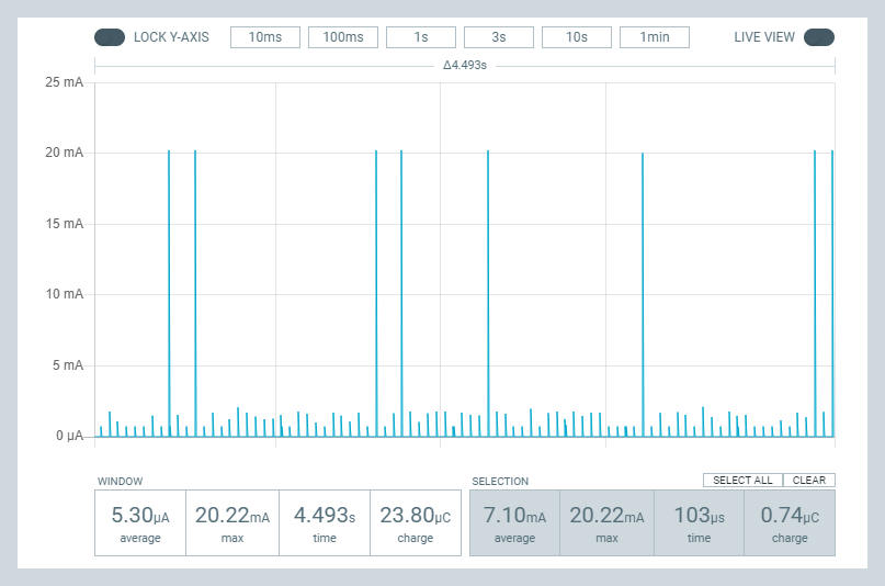
    It's about the same whether it's using DCDC mode or LDO mode when the system is sleeping in ON mode. When I first saw this plot I thought the MCU was waking up, doing something, and then falling back to sleep on what seemed like a very repeatable periodicity. I even went hunting for some part of the system that I had forgotten to turn-off that might be causing this behavior. However, when that hunt didn't turn up anything, my present theory is that this is just how the low power mode works when the system is ON but in sleep mode: it maybe is more efficient to sip current at periodic intervals than it is to run the LDO/DCDC continuously.

    Now that you've seen the above picture of the spikey nature in which a nRF52 module draws its sleep current, you can appreciate that using a uCurrent Gold or a Current Ranger (let alone a multimeter) to measure sleep current is likely to give an erroneously low measurement: these pulses pass by too quickly for such a meter to properly register. That's why, for instance, I began to suspect that this guy's measurements were possibly too low:
    Pro Mini nRF52: Less than 2µA System ON Sleep from 3v – 01:08
    — Pro Mini Micros

    Indeed, when I hook my same sleeping module up to a current ranger, the current ranger shows 0.0ua when set in ua mode. In na mode, though, the measurements are jumping around all over the place. The point being: if that was all I had to go on, I'd probably erroneously conclude that the sleep current was something less than 1ua, whereas the PPK2 here is reporting an average 5.3ua within its measurement window.

    What remains unexplained is why the average current draw I measured with PPK2 while sleeping like this is so high. According to the nRF52805 datasheet, the current drawn while sleeping in system ON mode with full memory retention should be just 0.8ua.

    datasheet_sleep_current_nRF52805.JPG

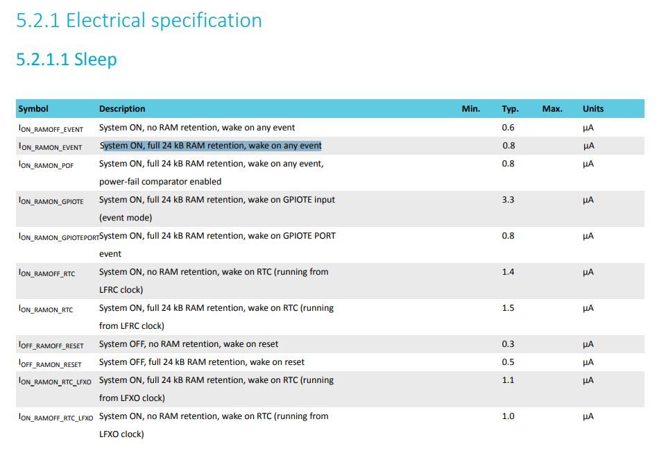
    and so I'm not sure why I'm experiencing so much more than that (5.3ua in this PPK2 example), unless maybe it's something about the Fanstel BC805M module that it's a part of which is raising the sleep current. If so, that would certainly be disappointing: I bought it precisely because the nRF52805 is supposed to have such a low sleep current compared to the other Nordic nRF52 chips that are out there.

    As a matter of fact, the spikey nature of the current draws led me to wonder whether maybe the PPK2 itself was perhaps not measuring the current correctly. So, to answer that, I added a 220uF bypass ceramic capacitor (i.e. between VCC and GND) near the nRF52805 module to better average out the current draw seen by the PPK2, and then I measured using the PPK2 again. Guess what? Now the PPK2 measures an average of 0.81ua, which is spot-on with what the datasheet predicted. Whew! What a relief. I find this new measurement trustworthy not only because (a) it agrees with the value predicted by the datasheet, but now also (b) both a PPK2 and a Current Ranger produce current measurements that agree with one another, and (c) by averaging out the current draw, the potential problems stemming from a highly spikey measurement are cast aside.


  • @NeverDie have you checked the radio already? How much work is needed to make it work with mysensors?


  • Hero Member

    @monte said in GUIDE - NRF5 / NRF51 / NRF52 for beginners:

    @NeverDie have you checked the radio already? How much work is needed to make it work with mysensors?

    Answering your question: Presently taking baby steps. Using pseudo bare metal programming I have it sending and receiving very simple packets using the proprietary mode radio at 2mbps. Nothing fancy. Just the bare minimum. But it works, and the code is portable with no meaningful library dependencies other than just regular C-language libraries like string.h. 🙂 After I clean up the code I'll post it to github. I had already posted it on github in micropython and forth, and I just recently translated it back into C (which is what I had started with originally but didn't save the code 🙄 ). Anyhow, the benefit of writing it in pseudo bare metal is that it should pretty much compile without changes and run no matter which tool chain you're using (Sandeep, SES, or whatever). 🙂

    You know, it occurs to me that we should upload not just the source code, but a full VM of the development environment used to compile, link, and upload it. That would be smart. After all, all projects become time capsules, and who knows what toolchain or library will be in vogue years down the line when you want to make some change in the code you've written. If it's all in a VM, then you can step back right where you were without missing a beat. Hmmm.... I like this idea. So obvious, yet so powerful. The only problem I foresee is that J-link license is bound to the particular nRF52-DK that you own, so at least that part might make sharing a common VM a bit awkward. Everything would need to be either open source or free to use for a shared VM to work without incurring problems of its own.

    But, anyway, details aside, a shared VM development platform would create a stable starting place for any newcomer who comes along. Even if the setup instructions are current at the moment they are written, over time entropy kicks in and eventually....you all know how that goes.....

    And not just SW development. HW development too. For instance, rather than share just a kicad archive, if you could share a VM of the entire kiCad that you used to create a PCB.... that would be the ultimate. Then, if KiCad 7 comes along and isn't fully backward compatible with KiCad 6, everything still works just as well as it always did the moment you finished with it.


  • @NeverDie are you saying it is only programmable with j-link? Won't stlink/blackmagic work?


  • Hero Member

    @monte said in GUIDE - NRF5 / NRF51 / NRF52 for beginners:

    @NeverDie are you saying it is only programmable with j-link? Won't stlink/blackmagic work?

    🤦 Yes, you're right. Either of those should work. I happen to be using j-link, so that gave me tunnel vision, but if either or those were the basis, then problem solved!

    BTW, I just now checked, and the module I'm using literally does fit on a dime:
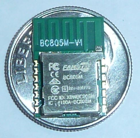
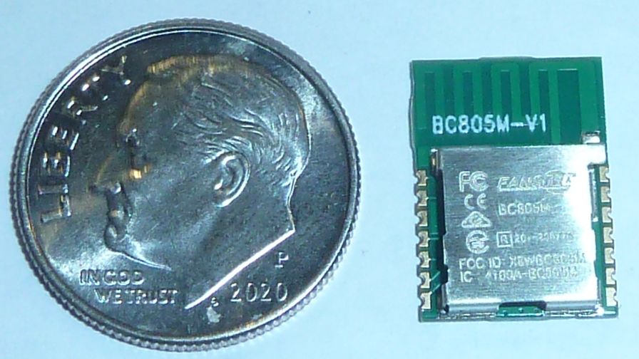
    bc805m_on_dime.JPG bc805m_beside_dime.JPG
    $2.50 each.


  • @NeverDie sorry, where did you buy them? I don't see them anywhere 😞


  • Hero Member

    @monte said in GUIDE - NRF5 / NRF51 / NRF52 for beginners:

    @NeverDie sorry, where did you buy them? I don't see them anywhere 😞

    https://www.fanstel.com/buy/bt832f-low-cost-longer-range-bluetooth-50-module-cjtrx-8shlz-r7a7z

    Presently sold-out of this particular model, but if you watch for it, it seems to come back into stock fairly often. When I was buying they had only 10 in stock, so I bought all ten. Then the next day they had another 15 in stocki, so I bought all 15. Then they were out of stock for a while, but then recently they re-stocked. Apparently that didn't last, because now they are already out of stock again.


  • @NeverDie yep, you're lucky:) Mouser says "Expected 09-Dec-22"


  • Hero Member

    @monte There are $1.59-$2.39 nRF52805 Minew modules on Alibaba: https://minewtech.en.alibaba.com/search/product?SearchText=nrf52805
    The size is just a couple mm larger than the the dime sized BC805M (above photos). I've never ordered from Alibaba so I can't really say how well that may or may not go. i.e. maybe it's a good deal, or maybe it's clickbait pricing and they hammer you on shipping. For instance, unlike Aliexpress, I don't see a rapid way to place an order, which is kinda weird given that the minimum order is just quantity 3. I assume one has to send the seller an RFQ indicating the quantity desired, and then the seller responds with a price that includes shipping? Anyone know if that's how it works? Obviously I have no idea where the breakpoint is, but maybe if you were to order 20 or 30 you'd come out ahead vs ordering from Aliexpress.


  • @NeverDie I contacted alibaba sellers a few times for quotes, but never got to buy anything:) The process and shipping costs kills any wish to try and buy if anything less then 20-50...


  • Hero Member

    Reporting back: Yeah, I just now contacted them. The price they're quoting now is $3.89 per module and they want $35 shipping. They said "Mass production is about 2.5-2.2 USD", which is higher than what their Alibaba listing says for quantity 3 sample pricing, which they now say is 2 years out date and should be ignored. Checking, I see that the quoted pricing is actually slightly worse than the $3.82/unit in their Aliexpress store. What a joke. I mean, given that this is allegedly the manufacturer talking, who can't be bothered to keep their own Alibaba listing updated even though it's allegedly two years out of date.... I guess the pricing indicated on Alibaba means nothing, which certainly explains a lot.


  • Hero Member

    One shortcoming of the nRF52805 that I just ran across: it has no LPCOMP. I'm surprised, as it's rather basic functionality.


  • Hero Member

    On the other hand, the nRF52805 does have PORT DETECT, which appears can provide the basic wake-up functionality at no penalty to current consumption. i.e. total sleep current remains at 0.8ua with full memory retention. AFAIK, that's still better than any of the other nRF52xxx chips Nordic has so far made, and in that one respect also better than what the nRF5340 can achieve. That compares to 0.5ua current draw when the nRF52805 is in OFF mode, with no memory retention, but where PORT DETECT could still be used to wake-up the nRF52805. So, the interesting question remains: how many mah are consumed by going from stone-cold 0ua OFF to full-on? Knowing that, one could compute the tradeoff of going that route vs sleeping at 0.8ua or 0.5ua. If the stone-cold OFF interval is long enough, it will win, and so the only unknown (currently) is how long that interval needs to be to reach a break-even point, and beyond that the energy savings pile up.


  • @NeverDie Oh I've been running around 20 NRF52805 nodes for the past ~2 years https://forum.mysensors.org/post/108893. They've been working very well for me.

    edit:
    PRs to get working with mysensors
    https://github.com/sandeepmistry/arduino-nRF5/pull/442
    https://github.com/mysensors/ArduinoHwNRF5/pull/12


  • Hero Member

    Reporting back: I did the measurements, and it takes an nRF52805 about 750uSec to go from cold-start to turning on an LED, at an average current drain of about 330ua just prior to the LED turning on. Of course, the 805 may have to spend additional time and current to re-establish a particular context, but ignoring that, the measurements suggest a breakeven point between cold-start vs sleeping with the RTC turned-on and full memory retained (roughly 1.5ua current draw) is approximately 200ms. The downside is that it would require additional hardware to benefit from the arbitrage, but if so desired it could be done. In fact, just knowing that's it's possible makes me want to try it! 😎


  • Hero Member

    @ncollins Impressive! Looks as though you even modeled the exact shape of the coincell holder. And you apparently designed the 3D printer snap enclosures as well. Even just the 3D printed enclosure modelling is quite a task all by itself. I hope to one day evolve into doing that too, but for now the Hammond enclosures are going to be my short-term solution. The smallest Hammond is still not as small as what you've managed to produce, but at 36mm wide for an off-the-shelf ABS enclosure, it's too wide by only about 10mm. Still.... one day I want to 3D print an enclosure to be as small as possible.


Log in to reply
 

Suggested Topics

13
Online

11.2k
Users

11.1k
Topics

112.5k
Posts