Latest beta build of Domoticz (9379) crashes when adding new sensors
-
@GertSanders
Hi Gert. Any luck? -
@GertSanders
Hi Gert. Any luck?@alexsh1 nope. The atmega328p's all work properly and get recognised. The atmega1284p never gets a reply.
I'm wondering if it has to do with the selection of pinout. I selected "Standard" pinout, which is a pin definition used in AVR Freaks site. There is also Bobuino and Sanguino. Still need to test those. -
@GertSanders
Hi Gert. Any luck?@alexsh1
SOLVED: the problem with my atmega1284p was the mapping of the CE pin.
I needed to add the following to my sketch:
#define MY_RF24_CE_PIN 1
The reason is that I used a "standard" pinout, so CE is not on Arduino pin 9.
In my pin-definition "CE" is Arduino pin 1 or chip pin PB1.
There are several mappings possible for this chip:
https://github.com/MCUdude/MightyCore
So I need to look at the pin mapping again, and may refresh the boot loader with one of the MightyCore boot loaders ( I flashed this chip back in early 2015).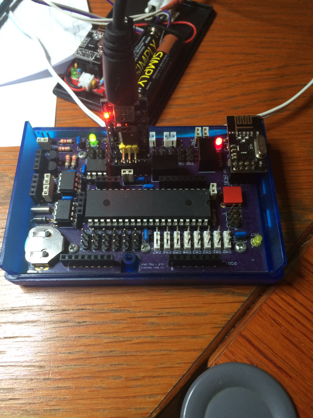
I use the following mapping:
// ATMEL ATMEGA1284P
//
//                   +---\/---+
//           (D 0) PB0  1|        |40  PA0 (AI 0 / D24)
//           (D 1) PB1  2|        |39  PA1 (AI 1 / D25)
//      INT2 (D 2) PB2  3|        |38  PA2 (AI 2 / D26)
//       PWM (D 3) PB3  4|        |37  PA3 (AI 3 / D27)
//    PWM/SS (D 4) PB4  5|        |36  PA4 (AI 4 / D28)
//      MOSI (D 5) PB5  6|        |35  PA5 (AI 5 / D29)
//  PWM/MISO (D 6) PB6  7|        |34  PA6 (AI 6 / D30)
//   PWM/SCK (D 7) PB7  8|        |33  PA7 (AI 7 / D31)
//                 RST  9|        |32  AREF
//                 VCC 10|        |31  GND
//                 GND 11|        |30  AVCC
//               XTAL2 12|        |29  PC7 (D 23)
//               XTAL1 13|        |28  PC6 (D 22)
//      RX0 (D 8)  PD0 14|        |27  PC5 (D 21) TDI
//      TX0 (D 9)  PD1 15|        |26  PC4 (D 20) TDO
// RX1/INT0 (D 10) PD2 16|        |25  PC3 (D 19) TMS
// TX1/INT1 (D 11) PD3 17|        |24  PC2 (D 18) TCK
//      PWM (D 12) PD4 18|        |23  PC1 (D 17) SDA
//      PWM (D 13) PD5 19|        |22  PC0 (D 16) SCL
//      PWM (D 14) PD6 20|        |21  PD7 (D 15) PWM
//                   +--------+
//
And there is some renaming here:
static const uint8_t SS   = 4;
static const uint8_t MOSI = 5;
static const uint8_t MISO = 6;
static const uint8_t SCK  = 7;

static const uint8_t SDA = 17;
static const uint8_t SCL = 16;
static const uint8_t LED = 7;

static const uint8_t A0 = 24;
static const uint8_t A1 = 25;
static const uint8_t A2 = 26;
static const uint8_t A3 = 27;
static const uint8_t A4 = 28;
static const uint8_t A5 = 29;
static const uint8_t A6 = 30;
static const uint8_t A7 = 31;
So most pins mapped correctly, except for CE ...
fixed now with the #define
-
@alexsh1
SOLVED: the problem with my atmega1284p was the mapping of the CE pin.
I needed to add the following to my sketch:
#define MY_RF24_CE_PIN 1
The reason is that I used a "standard" pinout, so CE is not on Arduino pin 9.
In my pin-definition "CE" is Arduino pin 1 or chip pin PB1.
There are several mappings possible for this chip:
https://github.com/MCUdude/MightyCore
So I need to look at the pin mapping again, and may refresh the boot loader with one of the MightyCore boot loaders ( I flashed this chip back in early 2015).I use the following mapping:
// ATMEL ATMEGA1284P
//
//                   +---\/---+
//           (D 0) PB0  1|        |40  PA0 (AI 0 / D24)
//           (D 1) PB1  2|        |39  PA1 (AI 1 / D25)
//      INT2 (D 2) PB2  3|        |38  PA2 (AI 2 / D26)
//       PWM (D 3) PB3  4|        |37  PA3 (AI 3 / D27)
//    PWM/SS (D 4) PB4  5|        |36  PA4 (AI 4 / D28)
//      MOSI (D 5) PB5  6|        |35  PA5 (AI 5 / D29)
//  PWM/MISO (D 6) PB6  7|        |34  PA6 (AI 6 / D30)
//   PWM/SCK (D 7) PB7  8|        |33  PA7 (AI 7 / D31)
//                 RST  9|        |32  AREF
//                 VCC 10|        |31  GND
//                 GND 11|        |30  AVCC
//               XTAL2 12|        |29  PC7 (D 23)
//               XTAL1 13|        |28  PC6 (D 22)
//      RX0 (D 8)  PD0 14|        |27  PC5 (D 21) TDI
//      TX0 (D 9)  PD1 15|        |26  PC4 (D 20) TDO
// RX1/INT0 (D 10) PD2 16|        |25  PC3 (D 19) TMS
// TX1/INT1 (D 11) PD3 17|        |24  PC2 (D 18) TCK
//      PWM (D 12) PD4 18|        |23  PC1 (D 17) SDA
//      PWM (D 13) PD5 19|        |22  PC0 (D 16) SCL
//      PWM (D 14) PD6 20|        |21  PD7 (D 15) PWM
//                   +--------+
//
And there is some renaming here:
static const uint8_t SS   = 4;
static const uint8_t MOSI = 5;
static const uint8_t MISO = 6;
static const uint8_t SCK  = 7;

static const uint8_t SDA = 17;
static const uint8_t SCL = 16;
static const uint8_t LED = 7;

static const uint8_t A0 = 24;
static const uint8_t A1 = 25;
static const uint8_t A2 = 26;
static const uint8_t A3 = 27;
static const uint8_t A4 = 28;
static const uint8_t A5 = 29;
static const uint8_t A6 = 30;
static const uint8_t A7 = 31;
So most pins mapped correctly, except for CE ...
fixed now with the #define
@gertsanders that’s interesting. How exactly do you connect nrf24l01+?
I have Mightyduinohttp://www.innovafabs.eu/index.php?route=product/category&path=18_64
Glad you sorted it out
-
@gertsanders that’s interesting. How exactly do you connect nrf24l01+?
I have Mightyduinohttp://www.innovafabs.eu/index.php?route=product/category&path=18_64
Glad you sorted it out
MISO, MOSI and SCK are connected to the pins that carry this function
CE -> PB1
CSN -> PB4I use PB0 to show a flashing in the bootloader.
-
MISO, MOSI and SCK are connected to the pins that carry this function
CE -> PB1
CSN -> PB4I use PB0 to show a flashing in the bootloader.
@gertsanders Thank you! You are using prototype wires or did you come up with a PCB adapter? I would like to MySensorise it, but would rather use an adapter.
I also wish there was a solder joint for the power LED
-
@gertsanders Thank you! You are using prototype wires or did you come up with a PCB adapter? I would like to MySensorise it, but would rather use an adapter.
I also wish there was a solder joint for the power LED
@alexsh1 hi Alex, it is how I routed my PCB.
-
@alexsh1 hi Alex, it is how I routed my PCB.
@gertsanders but do you have an adapter PCB like this one
https://oshpark.com/shared_projects/CtW4Xaow
or connect your PCB with wires?
-
@gertsanders but do you have an adapter PCB like this one
https://oshpark.com/shared_projects/CtW4Xaow
or connect your PCB with wires?
@alexsh1
I have a DIL connector on my PCB, and the nrf24l01+ plugs into it. On my testboard I'm still using the non-smd version. -
@alexsh1
I have a DIL connector on my PCB, and the nrf24l01+ plugs into it. On my testboard I'm still using the non-smd version.@gertsanders said in Latest beta build of Domoticz (9379) crashes when adding new sensors:
DIL connector
:+1:
I do not have a PCB. I have the atmega1284p board (Mightyduino) -> https://oshpark.com/shared_projects/zuZ4OIaeand would like to have a moteino like board with either nrf24l01+ or rfm69 on it
I can use wires to connect a transceiver but would like to have a neat solution
Hello! It looks like you're interested in this conversation, but you don't have an account yet.
Getting fed up of having to scroll through the same posts each visit? When you register for an account, you'll always come back to exactly where you were before, and choose to be notified of new replies (either via email, or push notification). You'll also be able to save bookmarks and upvote posts to show your appreciation to other community members.
With your input, this post could be even better 💗
Register Login