How to read frequency and SWP output from watermark sensor
-
@hard-shovel
Hello,it's verry interresting what you shared.
Today I left the SMX input open. No sensor no resistance. I discovered, I get the same value when the sensor is in a fully dried soil. And I did not have the sensor with me.Yes, I have a box that I fill up with soil of the crop where the sensors will be for the measurement.
We only want to monitor the soil moiture from June to Septembre and the result will be display in a graph.Some week ago, I wrote a loop to simulate the watermark voltage. In your second table you show that KPA can be from -332 to -1300 and then immediately to a positif number. That difference make me souspicious. I am still souspicous when I look from 48Hz to 157Hz (the doc give a range of frequency from 48Hz to 13233Hz.)
But at the final, as I understood, what is relevant is from 1220Hz to +/- 310hz (from 550Ohm to 27950). From 27950 and above, the soil is fully dry, whatever if the kPa goes to -1300 or -352. And from 550Ohm or below, the soil is fully wet.
@pierrot10
Yes i think that is correct 550 Ohm to 27950 Ohms is the range for the watermark sensor.For the SMX module with input open no sensor should be 48Hz as you have already discovered, and if you short the input terminals out you should get 13233Hz so total range of the module is more than the sensor.
-
@pierrot10
Yes i think that is correct 550 Ohm to 27950 Ohms is the range for the watermark sensor.For the SMX module with input open no sensor should be 48Hz as you have already discovered, and if you short the input terminals out you should get 13233Hz so total range of the module is more than the sensor.
@hard-shovel
I think, now it's clearer for me.First, SMX module has a range from 48hz to 13233hz
But the watermak sensor has a range from 550 to 27950 ohmAs we use watermark to measure the soil mostire, wehave to consier the range of 550 to 27950 which match with 6700Hz (more or less) and 310Hz. What is below or above is not relevant for moisture measurement with Wathermark.
Are you agree with me?
-
@hard-shovel
I think, now it's clearer for me.First, SMX module has a range from 48hz to 13233hz
But the watermak sensor has a range from 550 to 27950 ohmAs we use watermark to measure the soil mostire, wehave to consier the range of 550 to 27950 which match with 6700Hz (more or less) and 310Hz. What is below or above is not relevant for moisture measurement with Wathermark.
Are you agree with me?
Yes I do agree that is how i understand the operation from the data sheet.
if your still concerned about the possibility of negative results you could add something like either of the following
Frequency = constrain(Frequency, 48, 133233);

or

Resistance = constrain(Resistance, 500, 27950);
My main concern in the long term would be the sensor connections being corroded and the sensor resistance becoming open. So error checking for higher or lower than normal values for sensor fault conditions might be worthwhile.
-
Dear hard-shovel,
I do not know if you are still around and if you can help me a bit.
I actually put into the soil a watermark at 20cm. I add some water to see the watermark measurement and I used your proposition (code)I can not understand why I have a WRm of 518 and it retrun me a 200kPa It should be 0
Getting WM1 (SMX):
Frequency at 15: 6896Hz WRM: 518
WRM: 518
WRMc: 518
SWP: 200
Here si the code:
Note: sw.something. The sw is beacuse I use Seesaw Seesaw borad from Adafruit to have more DIO// getting the swp. // wm1_power_pin is pin which ppower smx // wm1_power_pin is the pin read the value // val is the return value get_wmsmx(wm1_power_pin, wm1_read_pin, 1000000, val, true); mesMesures[c_wm1][capteur_wm1_id].valeur = val; // The final SWP is store hereDont pain attention at 'alternative'. It's alway true and I will clean the code.
void get_wmsmx(int powerPin, int pinRead, unsigned long timeout, int16_t &val, bool alternative)
 {
    sw.digitalWrite(powerPin, HIGH);
    delay(1000); // Need to have the sensor "in equilibre" with the soil.

    int highInput, lowInput;             // Store high and low time of wave in microseconds
    float totalInput;                     // Temp store of total time of duration for one cycle of high and low pulse
    float frequency;                      // calculated freqency   1/total time of one cycle.
    int16_t swp;
    int percent=0;
    int32_t wrm;
    //float Tsoil=24; //temp
    highInput = pulseIn(pinRead,HIGH);
    lowInput  = pulseIn(pinRead,LOW);
    totalInput = highInput + lowInput;

    frequency = 1000000 / totalInput;

    if (highInput >0 && lowInput>0)
    {
      Si.sprint(F("Frequency at "),2); Si.sprint(pinRead,2); Si.sprint(F(": "),2); Si.sprint((int16_t)frequency,2); Si.sprint(F("Hz "),2);
    }
    else
    {
      Si.sprint(F("frequency: "),2);
      Si.sprintln(F("Error"),2);
    }
    delay(500);

    sw.digitalWrite(powerPin, LOW);

    int16_t Tsoil = mesMesures[c_temperature_soil][capteur_temperature_soil_id].valeur;

    if(alternative == false)
    {
// That is my old code. I will remove it
      wrm = map(frequency,48,13233,27950,550); // Must control the frequency for 440 and 27950

      Si.sprint(F("WRM: "),2); Si.sprint(wrm,2); Si.sprintln(F(" Ohm"),2);
      Si.sprintln(F("Calculate SWP"),2);
      //kPa = (3.213 * kohms + 4.093) / (1 - 0.009733 * kohms - 0.01205 * Celsius)
      swp = (int16_t)(3.213 * (wrm/1000) + 4.093) / (1 - 0.009733 * (wrm/1000) - 0.01205 * Tsoil);
      Si.sprint(F("SWP: "),2); Si.sprint(swp,2); Si.sprint(F("kPa"),2);
      Si.sprint(F(" for a soil temp of "),2); Si.sprintln(Tsoil,2);

      //val = (int16_t)percent;
      val = swp;
    }
    else
    {
        resistanceCalc(frequency, wrm);
        Si.sprint(F("WRM: "),2);
        Si.sprintln(wrm,2);
        kPaCalc(wrm, Tsoil, swp);
        val = swp;
    }
    Si.sprint(F("SWP: "),2); Si.sprintln(swp,2);
 }
//--------------------------------------------------------------- void resistanceCalc(float frequencyInput, int32_t &wrm){ wrm=0; // Convert from freqency to Resistance measurement // From SMX.pdf datasheet, page 6 // 48 Hz = 10,000,000 Ohms // 76 Hz = 262,144 Ohms // 13233 Hz = 0 ohms // using lookup table held in the array RESISTORarray //frequencyInput = constrain(frequencyInput,50, 13233); //float newVal; if (frequencyInput <= RESISTORarray[0]) { // Minimum value wrm = RESISTORarray[0+1]; } if (frequencyInput >= RESISTORarray[74]) { // Maximum value wrm = RESISTORarray[74+1]; } for (int i=0; i<74; i=i+2) { if ((frequencyInput >= RESISTORarray[i]) && (frequencyInput <= RESISTORarray[i+2])) { wrm = RESISTORarray[i+1] - ((RESISTORarray[i+1]-RESISTORarray[i+3]) * ((frequencyInput-RESISTORarray[i]) / (RESISTORarray[i+2]-RESISTORarray[i]))); break; } } Si.sprint(F("WRM: "),2); Si.sprintln(wrm,2); }void kPaCalc(int32_t ResistanceInput, int16_t FTemperatureInput, int16_t &swp){ // Convert from Resistance to SWP kPa measurement // From SMX.pdf datasheet, page 7 // 550 Ohms = 0 SWP kPa // 6000 Ohms = 35 SWP kPa // 28075 Ohms =200 SWP kPa // using lookup table held in the array SWPkPAarray // table valid for temperature of 75F, 24C // for increase of 1°F increase resistance by 1%. // ** this function accepts temperature in Fahrenheit units ** //float newVal; // Adjust compensate resistance for temperature and cpnvert celculs to Fahrenheit // per page 8 of SMX.pdf swp=0; float ResistanceCompensated = ResistanceInput *(1 + 0.001*((FTemperatureInput * 1.8 + 32)-75)); Si.sprint(F("WRMc: "),2); Si.sprintln((int16_t)ResistanceCompensated,2); if (ResistanceCompensated <= SWPkPAarray[0]) { // Minimum value swp = SWPkPAarray[0+1]; } if (ResistanceCompensated >= SWPkPAarray[74]) { // Maximum value swp = SWPkPAarray[16+1]; } //for (int i=0; i<SWPkPAarray.length-2; i=i+2) { for (int i=0; i<16; i=i+2) { if ((ResistanceCompensated >= SWPkPAarray[i]) && (ResistanceCompensated <= SWPkPAarray[i+2])) { swp = SWPkPAarray[i+1] - ((SWPkPAarray[i+1]-SWPkPAarray[i+3]) * ((ResistanceInput-SWPkPAarray[i]) / (SWPkPAarray[i+2]-SWPkPAarray[i]))); break; } } //return newVal; }long RESISTORarray[76] = { // Watermark Sensor SMX interface Hz to Resistance lookup table per SMX.pdf page 6. 48, 10000000, 76, 262144, 85, 196608, 103, 131072, 122, 98304, 157, 65536, 194, 49152, 264, 32768, 335, 24567, 476, 16384, 612, 12288, 874, 8192, 1135, 6144, 1623, 4096, 2071, 3072, 2862, 2048, 3557, 1536, 4697, 1024, 5596, 768, 6932, 512, 7878, 384, 9104, 256, 9882, 192, 10802, 128, 11312, 96, 11893, 64, 12200, 48, 12526, 32, 12708, 24, 12871, 16, 12962, 12, 13047, 8, 13092, 6, 13139, 4, 13162, 3, 13186, 2, 13209, 1, 13233, 0, }; long SWPkPAarray[18]{ // Watermark Sensor SMX interface Resistance to SWP kPa lookup table per SMX.pdf page 7. // this table is valid at temperature of 75F, 24C 550, 0, 1000, 9, 1100, 10, 2000, 15, 6000, 35, 9200, 55, 12200, 75, 15575, 100, 28075, 200, };Many thank!!
-
yes you are correct, it should be 16.
-
Hello Hard-shovel !
Are you still around?
I ma still doubting about my SWP value returning by my sensor and by the code to calculate it.Until last week, I was used to use the great code you provide to me
resistanceCalc(frequency, wrm); Si.sprint(F("WRM: "),2); Si.sprintln(wrm,2); kPaCalc(wrm, Tsoil, swp); val = swp;But I was always suspicous about the SWP value. I also bout a WATER digital reader and the values never matched.
All the graph/line of Station3 is calculate with a temperature of 24Celcul. As sensor is in a room where the temeparture is between 24C and 28C, a small tolerence must be "accepted" :)Last week I used this to get the WRM (Watermark resistance)
wrm = map(frequency,48,13233,27950,550)but never use it. The result is wrong. I compared with datsheet of the Isometer and the result never matches.
However, your table works fine
//--------------------------------------------------------------- void resistanceCalc(float frequencyInput, int32_t &wrm){ wrm=0; // Convert from freqency to Resistance measurement // From SMX.pdf datasheet, page 6 // 48 Hz = 10,000,000 Ohms // 76 Hz = 262,144 Ohms // 13233 Hz = 0 ohms // using lookup table held in the array RESISTORarray //frequencyInput = constrain(frequencyInput,50, 13233); //float newVal; if (frequencyInput <= RESISTORarray[0]) { // Minimum value wrm = RESISTORarray[0+1]; } if (frequencyInput >= RESISTORarray[74]) { // Maximum value wrm = RESISTORarray[74+1]; } for (int i=0; i<74; i=i+2) { if ((frequencyInput >= RESISTORarray[i]) && (frequencyInput <= RESISTORarray[i+2])) { wrm = RESISTORarray[i+1] - ((RESISTORarray[i+1]-RESISTORarray[i+3]) * ((frequencyInput-RESISTORarray[i]) / (RESISTORarray[i+2]-RESISTORarray[i]))); break; } } Si.sprint(F("WRM: "),2); Si.sprintln(wrm,2); }In order to be fixed this question, I used my LoRa node to send the wrm, swp and a second swp to my server and observe the diffrence.
Look at this web page (go to Station 3)
Station 3 (Teste)Note:
Station 1 and 2 are two station on fields.
Station 3 is a node I have at home. I put a little of water on matrix of the watermark until the SWP go to 8kpa and left it dried 1,5 day until the the SWP is 200kps. one hour ago, I put the watermark sensor into water for one hour, and I am going to leave it drying under the sun and compare the graph. Today afternoon (15.9.2018), I am going to update the code of station 1 and 2 to get the SWP value with the equation of ShockThe red line is the WRM in Ohm and not ml/h (I have not change the unit).
The yellow line is the SWP return with the equation of Shockswp = (int16_t)(3.213 * (wrm/1000) + 4.093) / (1 - 0.009733 * (wrm/1000) - 0.01205 * Tsoil);and the violet line is the SWP return by
void kPaCalc(int32_t ResistanceInput, int16_t FTemperatureInput, int16_t &swp){ // Convert from Resistance to SWP kPa measurement // From SMX.pdf datasheet, page 7 // 550 Ohms = 0 SWP kPa // 6000 Ohms = 35 SWP kPa // 28075 Ohms =200 SWP kPa // using lookup table held in the array SWPkPAarray // table valid for temperature of 75F, 24C // for increase of 1°F increase resistance by 1%. // ** this function accepts temperature in Fahrenheit units ** //float newVal; // Adjust compensate resistance for temperature and cpnvert celculs to Fahrenheit // per page 8 of SMX.pdf swp=0; float ResistanceCompensated = ResistanceInput *(1 + 0.001*((FTemperatureInput * 1.8 + 32)-75)); Si.sprint(F("WRMc: "),2); Si.sprintln((int16_t)ResistanceCompensated,2); if (ResistanceCompensated <= SWPkPAarray[0]) { // Minimum value swp = SWPkPAarray[0+1]; } if (ResistanceCompensated >= SWPkPAarray[16]) { // Maximum value swp = SWPkPAarray[16+1]; } //for (int i=0; i<SWPkPAarray.length-2; i=i+2) { for (int i=0; i<16; i=i+2) { if ((ResistanceCompensated >= SWPkPAarray[i]) && (ResistanceCompensated <= SWPkPAarray[i+2])) { swp = SWPkPAarray[i+1] - ((SWPkPAarray[i+1]-SWPkPAarray[i+3]) * ((ResistanceInput-SWPkPAarray[i]) / (SWPkPAarray[i+2]-SWPkPAarray[i]))); break; } } //return newVal; }It's interresting to see that the kPaCalc() progress as a step and stop at 100kpa and jump at 200kpa only when the wrm is 27950.
I used
constrain (wrm,550,27950)so the wrm will not be display higher than 27950 even if it can go over 27950 as say the doc.
The equation of Shock look perfect and I controlled it with Watermark data reader. The result is similar with a tolerance of 5-10kpa.
From graph (See Station 3), I also compare the WRM and the SWP from the doc (see page 7) and SWP value matches.I wonder why, in the array
long SWPkPAarray[18]{ // Watermark Sensor SMX interface Resistance to SWP kPa lookup table per SMX.pdf page 7. // this table is valid at temperature of 75F, 24C 550, 0, 1000, 9, 1100, 10, 2000, 15, 6000, 35, 9200, 55, 12200, 75, 15575, 100, 28075, 200,you do not consider a SWP between 100kpa and 200kpa.
I thing it's very interresting to have value from 100kpa and 200kpa, as 100kpa is the moment when soil need to be irrigate and more we come close to 200kpa, more is dangerous.In any case, your function kPaCalc2() from the code you provided to me, 3 mounth ago seems to be best.
Thank for all
Cheers -
Hello Hard-shovel !
Are you still around?
I ma still doubting about my SWP value returning by my sensor and by the code to calculate it.Until last week, I was used to use the great code you provide to me
resistanceCalc(frequency, wrm);
        Si.sprint(F("WRM: "),2);
        Si.sprintln(wrm,2);
        kPaCalc(wrm, Tsoil, swp);
        val = swp;
But I was always suspicous about the SWP value. I also bout a WATER digital reader and the values never matched.
All the graph/line of Station3 is calculate with a temperature of 24Celcul. As sensor is in a room where the temeparture is between 24C and 28C, a small tolerence must be "accepted" :)Last week I used this to get the WRM (Watermark resistance)
wrm = map(frequency,48,13233,27950,550)but never use it. The result is wrong. I compared with datsheet of the Isometer and the result never matches.
However, your table works fine
//---------------------------------------------------------------
void resistanceCalc(float frequencyInput, int32_t &wrm){
  wrm=0;
  // Convert from freqency to Resistance measurement
  // From SMX.pdf datasheet, page 6
  // 48 Hz    = 10,000,000 Ohms
  // 76 Hz    =    262,144 Ohms
  // 13233 Hz =          0 ohms
  // using lookup table held in the array  RESISTORarray

  //frequencyInput = constrain(frequencyInput,50, 13233);
  //float newVal;
  if (frequencyInput <= RESISTORarray[0]) {     // Minimum value
    wrm = RESISTORarray[0+1];
  }
  if (frequencyInput >= RESISTORarray[74]) {     // Maximum value
    wrm = RESISTORarray[74+1];
  }
  for (int i=0; i<74; i=i+2) {
    if ((frequencyInput >= RESISTORarray[i]) && (frequencyInput <= RESISTORarray[i+2]))
    {
      wrm = RESISTORarray[i+1] - ((RESISTORarray[i+1]-RESISTORarray[i+3]) * ((frequencyInput-RESISTORarray[i]) / (RESISTORarray[i+2]-RESISTORarray[i])));
      break;
    }
  }
  Si.sprint(F("WRM: "),2); Si.sprintln(wrm,2);
}
In order to be fixed this question, I used my LoRa node to send the wrm, swp and a second swp to my server and observe the diffrence.
Look at this web page (go to Station 3)
Station 3 (Teste)Note:
Station 1 and 2 are two station on fields.
Station 3 is a node I have at home. I put a little of water on matrix of the watermark until the SWP go to 8kpa and left it dried 1,5 day until the the SWP is 200kps. one hour ago, I put the watermark sensor into water for one hour, and I am going to leave it drying under the sun and compare the graph. Today afternoon (15.9.2018), I am going to update the code of station 1 and 2 to get the SWP value with the equation of ShockThe red line is the WRM in Ohm and not ml/h (I have not change the unit).
The yellow line is the SWP return with the equation of Shockswp = (int16_t)(3.213 * (wrm/1000) + 4.093) / (1 - 0.009733 * (wrm/1000) - 0.01205 * Tsoil);and the violet line is the SWP return by
void kPaCalc(int32_t ResistanceInput, int16_t FTemperatureInput, int16_t &swp){
  // Convert from Resistance to SWP kPa measurement
  // From SMX.pdf datasheet, page 7
  //   550 Ohms =  0 SWP kPa
  //  6000 Ohms = 35 SWP kPa
  // 28075 Ohms =200 SWP kPa
  // using lookup table held in the array  SWPkPAarray
  // table valid for temperature of 75F, 24C
  // for increase of 1°F increase resistance by 1%.
  // ** this function accepts temperature in Fahrenheit units **
  //float newVal;


  // Adjust compensate resistance for temperature and cpnvert celculs to Fahrenheit
  // per page 8 of SMX.pdf
  swp=0;
  float ResistanceCompensated =  ResistanceInput *(1 + 0.001*((FTemperatureInput * 1.8 + 32)-75));
  Si.sprint(F("WRMc: "),2); Si.sprintln((int16_t)ResistanceCompensated,2);

    if (ResistanceCompensated <= SWPkPAarray[0]) {     // Minimum value
    swp = SWPkPAarray[0+1];
  }
  if (ResistanceCompensated >= SWPkPAarray[16]) {     // Maximum value
    swp = SWPkPAarray[16+1];
  }
  //for (int i=0; i<SWPkPAarray.length-2; i=i+2) {
  for (int i=0; i<16; i=i+2) {
    if ((ResistanceCompensated >= SWPkPAarray[i]) && (ResistanceCompensated <= SWPkPAarray[i+2])) {
      swp = SWPkPAarray[i+1] - ((SWPkPAarray[i+1]-SWPkPAarray[i+3]) * ((ResistanceInput-SWPkPAarray[i]) / (SWPkPAarray[i+2]-SWPkPAarray[i])));
      break;
    }
  }
  //return newVal;
}
It's interresting to see that the kPaCalc() progress as a step and stop at 100kpa and jump at 200kpa only when the wrm is 27950.
I used
constrain (wrm,550,27950)so the wrm will not be display higher than 27950 even if it can go over 27950 as say the doc.
The equation of Shock look perfect and I controlled it with Watermark data reader. The result is similar with a tolerance of 5-10kpa.
From graph (See Station 3), I also compare the WRM and the SWP from the doc (see page 7) and SWP value matches.I wonder why, in the array
long SWPkPAarray[18]{
// Watermark Sensor SMX interface Resistance to SWP kPa lookup table per SMX.pdf page 7.
// this table is valid at temperature of 75F, 24C
 550,  0,
1000,  9,
1100,  10,
2000,  15,
6000,  35,
9200,  55,
12200, 75,
15575, 100,
28075, 200,
you do not consider a SWP between 100kpa and 200kpa.
I thing it's very interresting to have value from 100kpa and 200kpa, as 100kpa is the moment when soil need to be irrigate and more we come close to 200kpa, more is dangerous.In any case, your function kPaCalc2() from the code you provided to me, 3 mounth ago seems to be best.
Thank for all
Cheers@pierrot10 the
redviolet line on the chart is showing an error in the processing as it should not jump in stages.The error has appeared as you changed the original code from using float for ResistanceInput to Integer, however there was also a error in the orginal code that did not show up when using the float inputs.
You only need to change this line and verify results
// swp = SWPkPAarray[i+1] - ((SWPkPAarray[i+1]-SWPkPAarray[i+3]) * ((ResistanceInput-SWPkPAarray[i]) / (SWPkPAarray[i+2]-SWPkPAarray[i])));to use ResistanceCompensated which is in float format.
swp = SWPkPAarray[i+1] - ((SWPkPAarray[i+1]-SWPkPAarray[i+3]) * ((ResistanceCompensated -SWPkPAarray[i]) / (SWPkPAarray[i+2]-SWPkPAarray[i])));Please test with values between 100 and 200 swp,
my results were
input Swp output
500Hz = 100swp
480hz = 105swp
435hz = 125swp
382Hz = 150swp
331Hz = 175swp
304Hz = 200swp -
@pierrot10 the
redviolet line on the chart is showing an error in the processing as it should not jump in stages.The error has appeared as you changed the original code from using float for ResistanceInput to Integer, however there was also a error in the orginal code that did not show up when using the float inputs.
You only need to change this line and verify results
// swp = SWPkPAarray[i+1] - ((SWPkPAarray[i+1]-SWPkPAarray[i+3]) * ((ResistanceInput-SWPkPAarray[i]) / (SWPkPAarray[i+2]-SWPkPAarray[i])));to use ResistanceCompensated which is in float format.
swp = SWPkPAarray[i+1] - ((SWPkPAarray[i+1]-SWPkPAarray[i+3]) * ((ResistanceCompensated -SWPkPAarray[i]) / (SWPkPAarray[i+2]-SWPkPAarray[i])));Please test with values between 100 and 200 swp,
my results were
input Swp output
500Hz = 100swp
480hz = 105swp
435hz = 125swp
382Hz = 150swp
331Hz = 175swp
304Hz = 200swp@hard-shovel said in How to read frequency and SWP output from watermark sensor:
the red line on the chart is showing an error in the processing as it should not jump in stages.
Hello, what do means by jump in stage with the red line?
Twice, the node could not send data but this due to a small error from me. Today, all data have been sent. Today, I left the node and the sensor outsite under the sun and I juts brang it back inside and the RWM went a little bit down. I am going to upload the code with your change, That great because right now the RWM is 88 -
@hard-shovel said in How to read frequency and SWP output from watermark sensor:
the red line on the chart is showing an error in the processing as it should not jump in stages.
Hello, what do means by jump in stage with the red line?
Twice, the node could not send data but this due to a small error from me. Today, all data have been sent. Today, I left the node and the sensor outsite under the sun and I juts brang it back inside and the RWM went a little bit down. I am going to upload the code with your change, That great because right now the RWM is 88@pierrot10 I meant the violet line should be a smooth similar to the yellow line.
-
@pierrot10 I meant the violet line should be a smooth similar to the yellow line.
@hard-shovel
Hello, Yes. Thank a lot to follow my topic :)
This morning I soaked it again the sensor into water for about 1 hour and I let it dry under the sun. It looks now really better ( See Station 3 ). I am happy with the result specially for Station 1 and 2 since yesterday 12h (UTC). Thanks a lot. -
@pierrot10 I meant the violet line should be a smooth similar to the yellow line.
@hard-shovel
Dear Hard-shovel.
In any case, thank a lot for your great help. Your participation helped me a lot and I would like to thank you again.
Now I am very happy with the result. I still keep an eye on it.First I planted them in 3 different level: 15cm, 30cm and 45cm. Then I replanted them to try to observe the bulb of water: I planted them at (distance/deepth) 15cm/30cm, 15cm/60cm and 30cm/30cm from the point where drop the water. (I also make sure that all sensor have a distance of 30cm from each other to avoid interfrences). But as the ground is tilted, the drop do not fall where I expected.
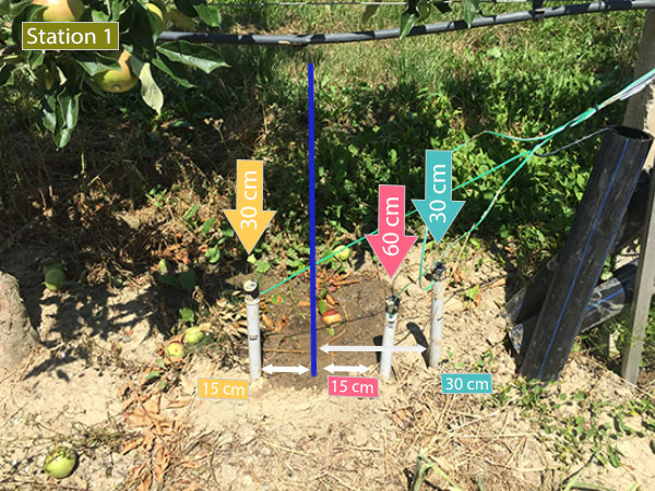
Next step, I am going to change the position of my 3 watermark, making sure that the drop falls on the line of the sensor, as the following:
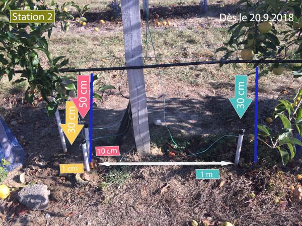
When I planted them into the soil and see the difference of the result.
Do you have any suggestion to plant the 3 sensor?
In any case, tanks a lot. You helped me a lot.
Enjoy the end of sommer!Cheers
-
@hard-shovel
Dear Hard-shovel.
In any case, thank a lot for your great help. Your participation helped me a lot and I would like to thank you again.
Now I am very happy with the result. I still keep an eye on it.First I planted them in 3 different level: 15cm, 30cm and 45cm. Then I replanted them to try to observe the bulb of water: I planted them at (distance/deepth) 15cm/30cm, 15cm/60cm and 30cm/30cm from the point where drop the water. (I also make sure that all sensor have a distance of 30cm from each other to avoid interfrences). But as the ground is tilted, the drop do not fall where I expected.
Next step, I am going to change the position of my 3 watermark, making sure that the drop falls on the line of the sensor, as the following:
When I planted them into the soil and see the difference of the result.
Do you have any suggestion to plant the 3 sensor?
In any case, tanks a lot. You helped me a lot.
Enjoy the end of sommer!Cheers
@pierrot10
Hi pierrot10 thank you for letting me know how it is working. I am glad to be of some help.
I have no experience of using the water sensors, I only looked at the data you posted and made a mock up of the converter module for testing.
My gardening is limited to two small potted plants that live on a window sill and have a capacitance sensor in each pot.
Best Regards -
@hard-shovel
It's a huge, great what you wrote!!!
I will test it tomorrow!!! and compare the two different to calculate kpa ( kPaCalc2() and kPaCalc() )
:+1:@pierrot10 Hi. Im very interested with your project because currently im doing a similar project. So, if u dont mind can i see how u setup the circuit because i want to compare with mine. Thank u. Hope u will reply my question^^
-
@pierrot10 Hi. Im very interested with your project because currently im doing a similar project. So, if u dont mind can i see how u setup the circuit because i want to compare with mine. Thank u. Hope u will reply my question^^
@suhaila96 Hello I have not seen your question since I reviewed this topics, today.
What do you mean about "setup your circuit"? How did you connected you watermark sensor and to what?