Introductions and Range Issues
-
@alowhum it might work better, but you'll need to consider if it is worth breaking the law.
In EU, the highest nrf24 channel that can be used legally is channel 83.
@mfalkvidd I also tried that outlaw trick and the results weren't satisfying :) I think that your microwave is more affecting the comunication than the wifi. This is another issue that I think that 2.4GHz is not suited for HA - can't turn on lights when using microwave is not acceptable :D
-
@sundberg84 said in Introductions and Range Issues:
I have around 25 nodes using Nrf24 radio. Once you have found your way and how to test them before deployment they work very good. Sure, its easier with the RFM69 but expensive and as @Yveaux said not 5v tolerant.
Yeah, they are really more expensive than the NRF24. But still cheaper than the cost of a repeater node (NRF24 + Nano) even without considering the power supply... Well, i guess that each case is different. :)
As for the 5v logic vs 3.3 thats also a problem with 5v Nanos. I think they need something like "this" ?
I'll still do tests with the NRF24/PA/LNA and with repeater nodes but i think i wont be so lucky with a weather station node (needs to be outside) that im planning to add to the system. Lets wait and see. :)
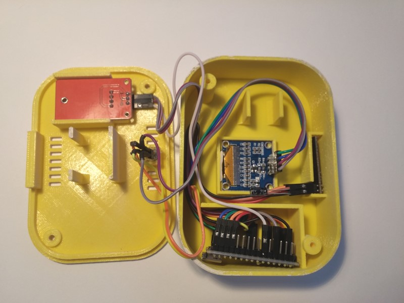
I'll also prepare the STL files to upload to Thingiverse of my box. Need to take some pictures of the assembly first. :)
Thanks for the input!
-
@sundberg84 said in Introductions and Range Issues:
I have around 25 nodes using Nrf24 radio. Once you have found your way and how to test them before deployment they work very good. Sure, its easier with the RFM69 but expensive and as @Yveaux said not 5v tolerant.
Yeah, they are really more expensive than the NRF24. But still cheaper than the cost of a repeater node (NRF24 + Nano) even without considering the power supply... Well, i guess that each case is different. :)
As for the 5v logic vs 3.3 thats also a problem with 5v Nanos. I think they need something like "this" ?
I'll still do tests with the NRF24/PA/LNA and with repeater nodes but i think i wont be so lucky with a weather station node (needs to be outside) that im planning to add to the system. Lets wait and see. :)
I'll also prepare the STL files to upload to Thingiverse of my box. Need to take some pictures of the assembly first. :)
Thanks for the input!
@titvs said in Introductions and Range Issues:
Yeah, they are really more expensive than the NRF24. But still cheaper than the cost of a repeater node (NRF24 + Nano) even without considering the power supply... Well, i guess that each case is different. :)
Both RFM and NRF modules needs power supplies and if the plan to have more than 2 modules the cost for a repeater is less than building two RFM modules. Its more about if you want to add more money for less hassle.
-
Hi everyone,
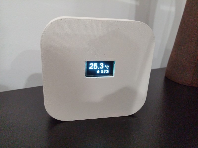
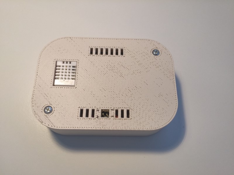
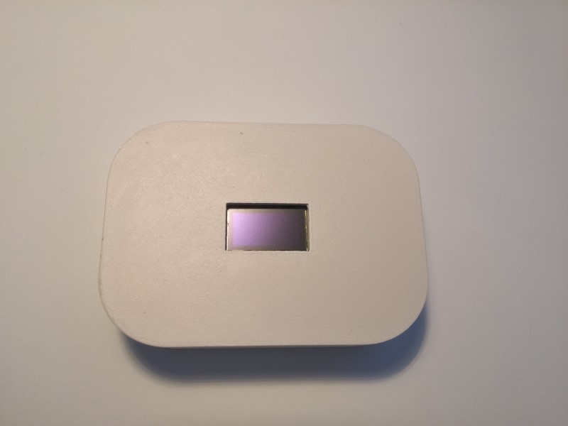
As promised, the box over at Thingiverse (smaller version):
https://www.thingiverse.com/thing:3019468
-
@titvs said in Introductions and Range Issues:
Anyway, I think there should be somekind of note on the radio page of the main website, stating this kind of problem regarding range and construction type.
I have around 25 nodes using Nrf24 radio. Once you have found your way and how to test them before deployment they work very good. Sure, its easier with the RFM69 but expensive and as @Yveaux said not 5v tolerant.
For me I have a fixed node on my lab-bench with a socket for the radio. This way I can test any new radio before I use them. Most of them work great with a 4,7uF cap. In your setup I would guess it will work much better once you get the gateway a proper and stable radio.
@sundberg84 said in Introductions and Range Issues:
@titvs said in Introductions and Range Issues:
Anyway, I think there should be somekind of note on the radio page of the main website, stating this kind of problem regarding range and construction type.
I have around 25 nodes using Nrf24 radio. Once you have found your way and how to test them before deployment they work very good. Sure, its easier with the RFM69 but expensive and as @Yveaux said not 5v tolerant.
For me I have a fixed node on my lab-bench with a socket for the radio. This way I can test any new radio before I use them. Most of them work great with a 4,7uF cap. In your setup I would guess it will work much better once you get the gateway a proper and stable radio.
Can I ask which kind of power supply you are using for the transceivers?
I have now tried various LDOs in a combination with various different kind of capacitors, RC filters, LC filters... but in the end I'm still not really satisfied and sometimes results are not repeatable.I currently have the best connection with a node whose radio is directly supplied by the power regulator of the Arduino pro mini. The Pro Minis are using MIC5205 LDOs which can only supply 150mA but are absolute low-noise regulators. The node is communicating with a gateway using the large NRF24L01 with external antenna, AMS1117 power regulator, an LC filter and at least 40µF worth of various ceramic capacitors. But this only started working properly since I shielded the radio with aluminum foil and moved the device away from other electronic devices (I assume the DIY style of homemade devices cannot cope with EMI as good as FCC approved consumer electronics can).
All other nodes are custom designed PCBs with the Atmega328 directly soldered onto it and a dedicated LDO for the radio. So far I've tried the LE33, AMS1117, LP2950ACZ and I have still unassembled boards designed to use an MCP1700 and an MIC5207 which I have not tried yet. Before I read into the theory of linear power regulators basically none of those variants worked reliably. Now that I realized that the LP2950ACZ for example has very very specific requirements for the ESR of the used filter caps, I desoldered my 47µF electrolytic cap on the radio and changed it to a 10µF ceramic cap. Now it works much more reliably but the connection is still spotty.
I am very eager to assemble the board with the MIC5207 because it has similar low-noise characteristics as the LDO of the Arduino Pro Mini.
In the end I am afraid that a lot of dangerious half-knowledge is being thrown around on this topic. Sometimes you hear that the problem with unreliable communications is caused by insufficient amount of power. My experience leads me to believe that in most of the cases the amount of power is absolutely not the problem (the LP2950ACZ can only supply 100mA but I still got them to kinda work). The main problem most people are fighting with is the power supply's noise. And this one is a bitch because the normal person without an oscilloscope cannot really measure and test this.
Now I am working on a revision of my standard PCB layouts which will include feed-through EMI filter capacitors, ferrite beads and a two-stage power regulation to filter the DC for the radios. Hopefully this will prove to work without failures.
Nevertheless I am really interested what other people who solved this problem are doing differently. -
@sundberg84 said in Introductions and Range Issues:
@titvs said in Introductions and Range Issues:
Anyway, I think there should be somekind of note on the radio page of the main website, stating this kind of problem regarding range and construction type.
I have around 25 nodes using Nrf24 radio. Once you have found your way and how to test them before deployment they work very good. Sure, its easier with the RFM69 but expensive and as @Yveaux said not 5v tolerant.
For me I have a fixed node on my lab-bench with a socket for the radio. This way I can test any new radio before I use them. Most of them work great with a 4,7uF cap. In your setup I would guess it will work much better once you get the gateway a proper and stable radio.
Can I ask which kind of power supply you are using for the transceivers?
I have now tried various LDOs in a combination with various different kind of capacitors, RC filters, LC filters... but in the end I'm still not really satisfied and sometimes results are not repeatable.I currently have the best connection with a node whose radio is directly supplied by the power regulator of the Arduino pro mini. The Pro Minis are using MIC5205 LDOs which can only supply 150mA but are absolute low-noise regulators. The node is communicating with a gateway using the large NRF24L01 with external antenna, AMS1117 power regulator, an LC filter and at least 40µF worth of various ceramic capacitors. But this only started working properly since I shielded the radio with aluminum foil and moved the device away from other electronic devices (I assume the DIY style of homemade devices cannot cope with EMI as good as FCC approved consumer electronics can).
All other nodes are custom designed PCBs with the Atmega328 directly soldered onto it and a dedicated LDO for the radio. So far I've tried the LE33, AMS1117, LP2950ACZ and I have still unassembled boards designed to use an MCP1700 and an MIC5207 which I have not tried yet. Before I read into the theory of linear power regulators basically none of those variants worked reliably. Now that I realized that the LP2950ACZ for example has very very specific requirements for the ESR of the used filter caps, I desoldered my 47µF electrolytic cap on the radio and changed it to a 10µF ceramic cap. Now it works much more reliably but the connection is still spotty.
I am very eager to assemble the board with the MIC5207 because it has similar low-noise characteristics as the LDO of the Arduino Pro Mini.
In the end I am afraid that a lot of dangerious half-knowledge is being thrown around on this topic. Sometimes you hear that the problem with unreliable communications is caused by insufficient amount of power. My experience leads me to believe that in most of the cases the amount of power is absolutely not the problem (the LP2950ACZ can only supply 100mA but I still got them to kinda work). The main problem most people are fighting with is the power supply's noise. And this one is a bitch because the normal person without an oscilloscope cannot really measure and test this.
Now I am working on a revision of my standard PCB layouts which will include feed-through EMI filter capacitors, ferrite beads and a two-stage power regulation to filter the DC for the radios. Hopefully this will prove to work without failures.
Nevertheless I am really interested what other people who solved this problem are doing differently.Can I ask which kind of power supply you are using for the transceivers?
Very different... mostly 2xAA but for AC-DC i use samsung and iphone charge/phone adapters. From 5 to 3.3v i use the ones in the Mysensors shop (LE33 and AMS1117).
The most important part is the capacitor as you know.in the end I am afraid that a lot of dangerious half-knowledge is being thrown around on this topic. Sometimes you hear that the problem with unreliable communications is caused by insufficient amount of power.
Trying to drive a PA/LNA with a LE33 is a to common issue and that is why you hear this alot but bad clones is even worse common issue. You never mention this, and if you are unlucky you can buy a batch of really crappy radios. I have had good batches (10/10), and some with 7 out of 10 worked but I have had a discussion with people with 10 bad radios.
It can be frustrating and hard to understand all this... but are you sure creating an advanced pcb with all those extra components will make it easier? Sure you can prove a point but it will be hard to do this for you unless you buy genuine radios and compare them.
-
Can I ask which kind of power supply you are using for the transceivers?
Very different... mostly 2xAA but for AC-DC i use samsung and iphone charge/phone adapters. From 5 to 3.3v i use the ones in the Mysensors shop (LE33 and AMS1117).
The most important part is the capacitor as you know.in the end I am afraid that a lot of dangerious half-knowledge is being thrown around on this topic. Sometimes you hear that the problem with unreliable communications is caused by insufficient amount of power.
Trying to drive a PA/LNA with a LE33 is a to common issue and that is why you hear this alot but bad clones is even worse common issue. You never mention this, and if you are unlucky you can buy a batch of really crappy radios. I have had good batches (10/10), and some with 7 out of 10 worked but I have had a discussion with people with 10 bad radios.
It can be frustrating and hard to understand all this... but are you sure creating an advanced pcb with all those extra components will make it easier? Sure you can prove a point but it will be hard to do this for you unless you buy genuine radios and compare them.
@sundberg84
Thanks for your answer. Currently I don't have any battery powered nodes but I assume that they cause a lot less headaches as you get a clean DC without the ripple and noise of AC/DC buck converters.If you are using LE33s, what exact capacitors are you choosing? Do you have low ESR electrolytics? Or does the LE33 also work reliably with normal ones? Maybe it's also a good choice of yours to use high quality charger / phone adapters. I bought a bunch of cheap phone chargers from Aliexpress and I suspect that they have a really dirty output since they even supply 5.4V and not around 5V. I have read that power regulators like e.g. the LE33 have a parameter called "ripple rejection" which states how much of the input power's ripple gets through to the regulated output. So if the input is bad enough, the output will also carry this noise.
What kind of behavior do you notice from bad radios? Don't they work at all or do they work and produce bad range? I personally also received two bad radios once but in that case they didn't work at all. Of course, this is easy to see, but diagnosing performance issues is much harder. Since I've heard this statement a lot in combination with the NRF24L01 radios I also changed my transceiver against a different batch, but I always get the same performance, independent from the specific radio. Nevertheless all my radios were bought from the cheapest supplier at AliExpress at that time.
Now the last thought: Most of my tryouts with my custom PCBs were done with the 2.3.0 version. My most stable node is still running 1.6. I have read here that there seems to be communication problems with the latest version. Also here I have found a bug report which maybe correlates with my bad experience.
-
@mathea90 said in Introductions and Range Issues:
If you are using LE33s, what exact capacitors are you choosing?
This depends, but mostly 4,7uF. Sometimes It works better with a 47uF cap. '
Do you have low ESR electrolytics?
Just regular cheap electrolytics caps.
good choice of yours to use high quality charger / phone adapters
Yes, and cheap are also very unsafe as well.
What kind of behavior do you notice from bad radios?
Most common, no reply / no connection at all unless very very close. Not that common that it works say 6m and not 15m.
2.3.0 version
I have been around since < 1.6 and I have never noised any bigger changes between the versions. I have understood there are some discussions around the RFM69 radio. I have nodes still from 1.4 and most from 2.0-2.2 and one from 2.3 but even though some are upgraded several times in different versions (same hardware) they perform the same. This makes me wonder still about the hardware quality of the radio...
-
2.3 issues mentioned are regarding rfm69 only, in special case: higher packet rate. even if it's weird it was ok with 2.2, it's mostly because for the moment there is no packet buffer/queue for rfm69, which exists for nrf24.
when you get better range/rssi etc by changing rf module, then it can be a bad/clone etc rf module.
when you get same range with all your modules, and range is poor, check points mentioned above ;) -
@titvs said in Introductions and Range Issues:
Anyway, I think there should be somekind of note on the radio page of the main website, stating this kind of problem regarding range and construction type.
I have around 25 nodes using Nrf24 radio. Once you have found your way and how to test them before deployment they work very good. Sure, its easier with the RFM69 but expensive and as @Yveaux said not 5v tolerant.
For me I have a fixed node on my lab-bench with a socket for the radio. This way I can test any new radio before I use them. Most of them work great with a 4,7uF cap. In your setup I would guess it will work much better once you get the gateway a proper and stable radio.
@sundberg84 I'm wondering if you use signing?
I could understand from other threads is that the usage of signing afects the performance of the NRF's becasue it somehow "pushes it to the limit". -
@sundberg84 I'm wondering if you use signing?
I could understand from other threads is that the usage of signing afects the performance of the NRF's becasue it somehow "pushes it to the limit". -
@sundberg84 I'm wondering if you use signing?
I could understand from other threads is that the usage of signing afects the performance of the NRF's becasue it somehow "pushes it to the limit".@joaoabs - no, im not using signing on the Nrf24l01+ network.
-
Today i made another couple of tests with a repeater to see if i can get signal from my first floor to the ground floor (where is the gateway) with promising results. Still waiting for my NRF24/PA/LNA to arrive still.
I was wondering if its ok to set the MY_RF24_PA_LEVEL to HIGH on all powered nodes (sensors, repeater and gateway), or the performance will be degraded?
Talking about the frequency ranges, i have a mesh of wifi Ubiquiti Unifi AP's in my house, which are able to do a RF scan and show me the channels that are more utilized. It seems the more crowded channels here are (20 MHz): 5 (2421-2443), 6 (2431-2453 MHz), and (40 MHz): 3 (2401-2443), 5 (2411-2453) and 9 (2431-2473).
With this in mind, im setting up my nodes on channel 2 (MY_RF24_CHANNEL 1 if im correct) where there is 0% utilization.PS: i have an original Nokia charger rated at 5v on the label but actually gives out 7v dc... Had another one rated at 5.4v but i measured aroud 7.6. Are these chargers supposed to work with a pre-determined load?
@titvs said in Introductions and Range Issues:
I was wondering if its ok to set the MY_RF24_PA_LEVEL to HIGH on all powered nodes (sensors, repeater and gateway), or the performance will be degraded?
Talking about the frequency ranges, i have a mesh of wifi Ubiquiti Unifi AP's in my house, which are able to do a RF scan and show me the channels that are more utilized. It seems the more crowded channels here are (20 MHz): 5 (2421-2443), 6 (2431-2453 MHz), and (40 MHz): 3 (2401-2443), 5 (2411-2453) and 9 (2431-2473).
With this in mind, im setting up my nodes on channel 2 (MY_RF24_CHANNEL 1 if im correct) where there is 0% utilization.Hi titvs,
-
I can remember that initially the MySensors library set the NRF24L01s power to "HIGH" by default. I just glanced at the API page to verify if this is still the case but it seems that now the default value has been set to "MAX" which is the highest possible power setting. In my experience if you know that you have enough supply power for the transceiver (in my case it even works with 100 mA 3.3V regulators) you can set the power "MAX" without a problem. In my case it increased the range a little bit and did not decrease the network quality. But keep in mind that the PA version of the NRF24L01 (the version with the power amplifier and large external antenna) is using significantly more power. So I assume you need a power source that can handle approximately >200 mA or even more.
-
I personally would just leave the MySensors network on its default channel. In the USA this channel is already out of the range of wifi. In Europe you theoretically could have an overlap but I personally have not experienced problems with this. IMO the problem with using lower channels is that wifi routers set to automatically search for the best channel could choose to just hop on your precious MySensors channel. Then your effors was just a waste of time and you have to manually change the firmware on every MySensors device again. If you use the MYSBootloader to flash FOTA updates, you are tied to use the default channel anyways.
--> Just to follow up on my previous post with my quality and reliability problems of the NRF24L01 transceivers: I think I was able to solve the problem as now my communication has been running flawlessly for over two days. The trick that seemed to work was to decouple the whole device from its power source input as much as possible by using an LC filter before going into the 3.3V LDO that supplies my transceivers. Previously I tried out everything to clean up the power supply AFTER the step down converter (also tried RC, LC filters, various capacitors...) but it didn't work reliably. I assume the problem with this is that some power regulators are absolutely pedantic about the ESR of their output capacitors. Playing around with various filter configurations on the output of the regulator maybe screwed up those values and caused the regulator to be unstable. Also I have no idea what I'm doing when I'm "designing" those filters, so I just randomly tried out various combinations of inductors and capacitors. So maybe this also caused more harm than good.
But now by putting the LC filter in between the output of the switching power adapter and the input of the LDO and keeping the output capacitors of the regulator exactly as specified in the data sheet, it basically solves all those problems. Basically the LDO doesn't care at all about the ESR or capacitor values at its input and also the chance that a badly designed LC filter is causing problems is much lower as the power regulator can dampen those influences afterwards.
So in my experience this configuration can solve most problems of bad communication due to dirty power supplies:
120V / 230V AC Mains --> Switching power adapter (5 - 24V DC with loads of ripple) --> LC / PI Filter (less ripple) --> linear LDO power regulator with output capacitors as specified in data sheet (clean 3.3V DC) --> NRF24L01+
-
-
@Mathea90 Thanks for your input. As for the wifi, im not using my router wifi network, i disabled it. My home wifi is a mesh of Ubiquiti Unifi APs managed by me... Cant remember if the channels are on auto though… :p
You also did an outstanding work with power supplies and filtering… Congratulations.This week i received my NRF24/PA/LNA so today i began testing range issues again. Well, i have a weird problem that i dont know if you guys already came across: since it is the amplified version, ive bought a dedicated power converter, something like this:
Ive tested it and its giving a constant voltage of 3.38v. I've connected it to the NRF24/PA/LNA (+ and ground) but the gateway (an Arduino UNO powered via USB) gave me an initialization error:
0;255;3;0;9;0 MCO:BGN:INIT GW,CP=RNNGA---,VER=2.3.0
0;255;3;0;9;4 TSM:INIT
0;255;3;0;9;6 TSF:WUR:MS=0
0;255;3;0;9;14 !TSM:INIT:TSP FAIL
0;255;3;0;9;17 TSM:FAIL:CNT=1
0;255;3;0;9;19 TSM:FAIL:DIS
0;255;3;0;9;22 TSF:TDI:TSLI've then connected the radio to the 3.3v and ground pins on the UNO and it works! What am i missing here?
For the time being the gateway is working ok but its being powered via USB (altough its a 3.0 port). Anyone tried this little modules before? It would suck if i discover i cant use it with the NRF24/PA/LNA...As for the range, im now getting good connection to a node that needed a repeater in between without the NRF24/PA/LNA so, so far so good. ;)
-
@yveaux well, i thought about that. a ground problem. But since the Arduino is powered via USB (+5V), should i also connect the ground from the 3.3v power supply to a ground pin on the arduino? how about the ground pin of the NRF24?
Thanks -
This post is deleted!