Everything nRF52840
-
@nagelc Not sure, but here's a guess: maybe generously tinning some braided wire so as to wick up the solder, dipping it in lots of flux, and then feeding it through the hole? Then when you apply heat from a soldering iron hopefully enough of the wicked solder would melt onto the pad to make a connection.
However, I presume the better way would be to apply solder paste on the pads before sticking on the module and then reflow it in an oven.
-
Hi everyone,
I'm a bit a newbie in hardware and need your help. I'm a PHD student and I actually work on ZigBee networks. For a POC, I need to have an hardware device able to capture and send ZigBee messages from a "true" physical device. (An old philips Hue or maybe an Ikea smartbulb for example - normally, 2.4GHz).
The idea is to make a false ZigBee Gateway to work on the secrurity of the enrolment in ZigBee 3.0 within software.
My issue is that I'm unfortunately a bit newbie in on-board programming and thus can't be sure if it's feasible and if it's really complicated or not. I'm posting my message here because the nrf52840 seems to fit my needs with a ZigBee compatibilty.
Thanks by advance for your answers ! -
hello @TruiteCendrée :grin:
yes this is possible with nrf52840, but unfortunately zigbee is not compatible with mysensors. Mysensors is a software stack like zigbee is.
I think you'll get more infos if you take a look on nordic semi forums. They have a zigbee stack for nrf52840.
-
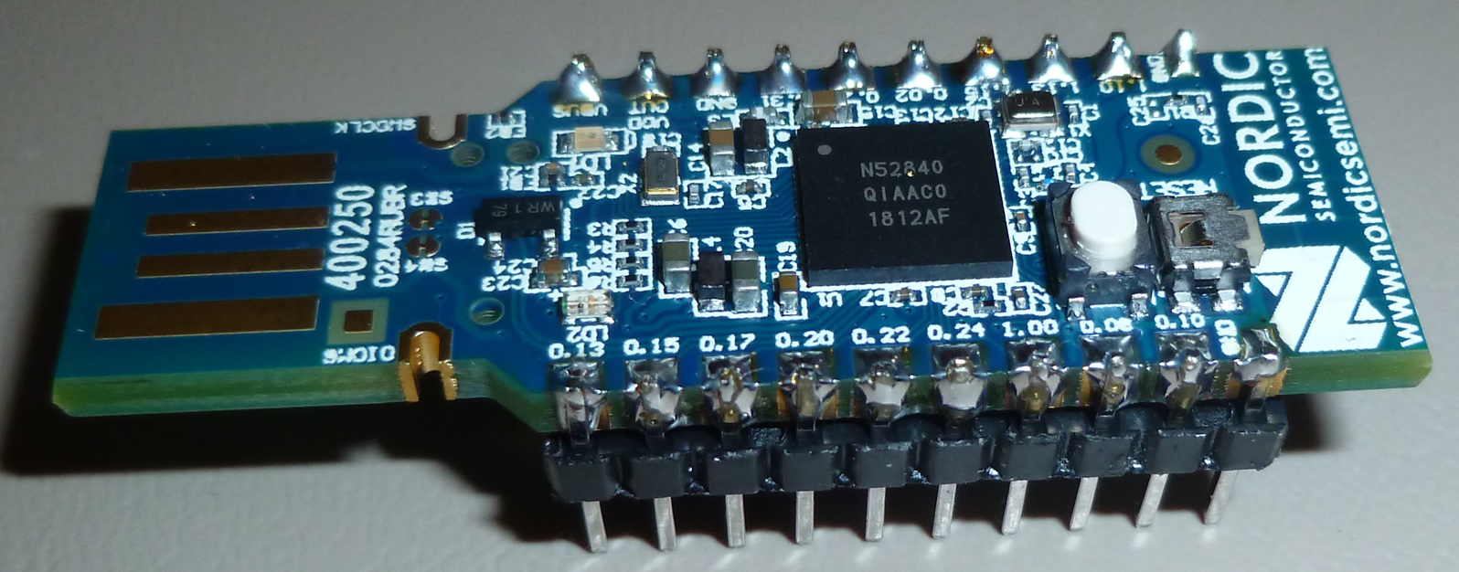
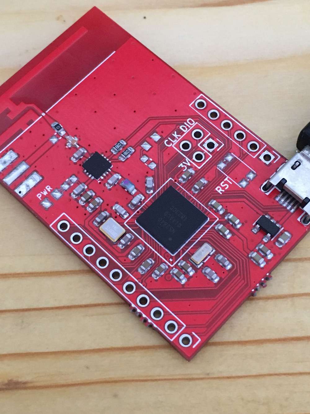
hey guys, i finally assembled my nrf52840 pa board. it was sitting there for quite some time but i couldn't find some spare time to get on with it but here are some experiences i had.
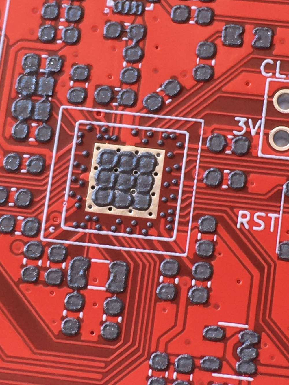
i was worried about this aQFN footprint but it all went well, looks like everything is soldered correctly and i ordered my boards with cheapest HASL instead of ENIG.
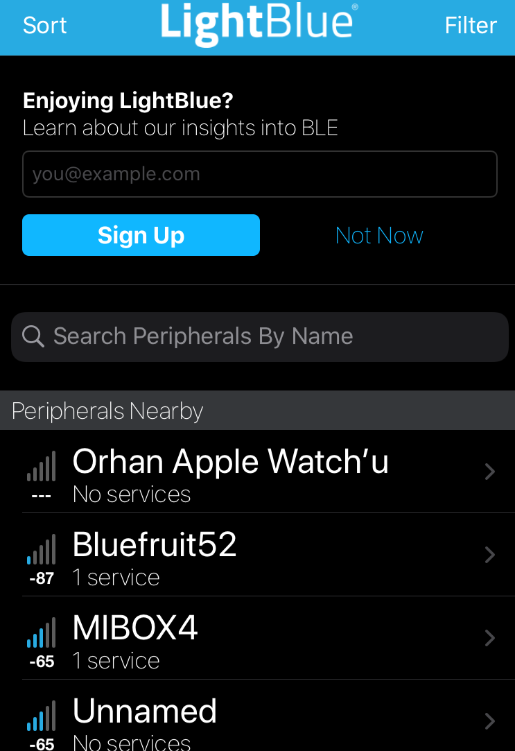
then i uploaded the adafruit feather bootloader to test the bluetooth and it all works ok. i used my iphone 6s as a central device and im not sure if my phone has LNA or PA module inside for bluetooth so it may or may not be better if i use another module like the one i did. this connection is from my module to my phone WITHOUT PA activated at tx power max(8):
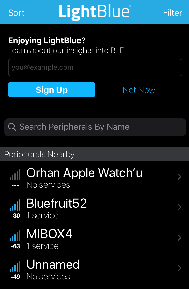
and this is after i activate PA chip on board :
and this is with 3 solid walls in between at around 10 meters distance
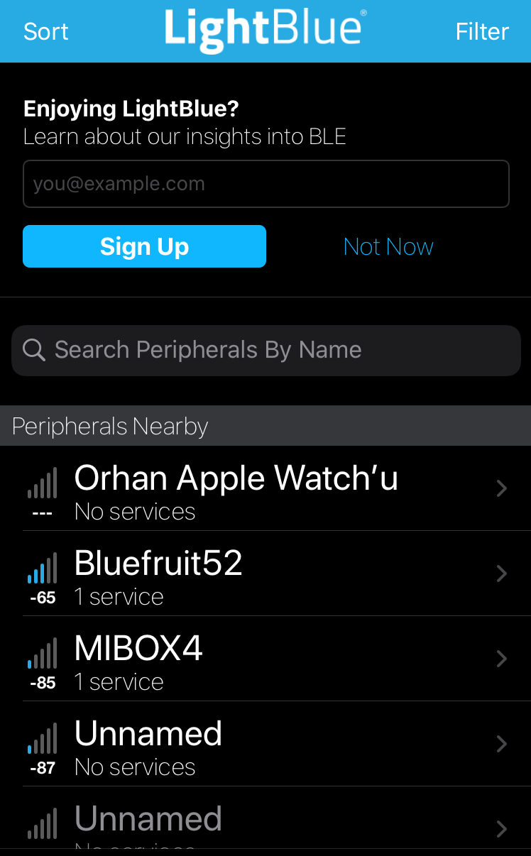
as you can see signal strength is massively different pa bumps up the signal from -87dbm to -30dbm which is probably day and night difference.
but with this setup you manually have to enable and disable rx and tx pins in order to keep the communication. well im not really good at coding but im going to try make the whole thing automatically because nordic already has this PA assist feature buried inside its BLE core, just gotta find a way to make it work.final board, forgot to add i opted to use pcb antenna but i could switch to external antenna as well i just have to reposition the 0 ohm resistor to use that SMA on the side and then results could get even better:
-
hey guys, i finally assembled my nrf52840 pa board. it was sitting there for quite some time but i couldn't find some spare time to get on with it but here are some experiences i had.
i was worried about this aQFN footprint but it all went well, looks like everything is soldered correctly and i ordered my boards with cheapest HASL instead of ENIG.
then i uploaded the adafruit feather bootloader to test the bluetooth and it all works ok. i used my iphone 6s as a central device and im not sure if my phone has LNA or PA module inside for bluetooth so it may or may not be better if i use another module like the one i did. this connection is from my module to my phone WITHOUT PA activated at tx power max(8):
and this is after i activate PA chip on board :
and this is with 3 solid walls in between at around 10 meters distance
as you can see signal strength is massively different pa bumps up the signal from -87dbm to -30dbm which is probably day and night difference.
but with this setup you manually have to enable and disable rx and tx pins in order to keep the communication. well im not really good at coding but im going to try make the whole thing automatically because nordic already has this PA assist feature buried inside its BLE core, just gotta find a way to make it work.final board, forgot to add i opted to use pcb antenna but i could switch to external antenna as well i just have to reposition the 0 ohm resistor to use that SMA on the side and then results could get even better:
-
@NeverDie i had to use stencil because i cant inspect aQFN soc from outside. as you can see every pin is at the bottom of it and they are very tiny. to make sure theres correct amount theres no other way than using stencil. to be honest i was expecting problems but it was ok :)
-
after abit of looking around and testing i think i made it work at least examples are quite responsive without a single disconnect. i had to add some header files and extra bit of code to every sketch so the knows how to use PA/LNA.
static void pa_lna_assist(uint32_t gpio_pa_pin, uint32_t gpio_lna_pin)
{
    ret_code_t err_code;

    static const uint32_t gpio_toggle_ch = 0;
    static const uint32_t ppi_set_ch = 0;
    static const uint32_t ppi_clr_ch = 1;

    // Configure SoftDevice PA/LNA assist
    ble_opt_t opt;
    memset(&opt, 0, sizeof(ble_opt_t));
    // Common PA/LNA config
    opt.common_opt.pa_lna.gpiote_ch_id  = gpio_toggle_ch;        // GPIOTE channel
    opt.common_opt.pa_lna.ppi_ch_id_clr = ppi_clr_ch;            // PPI channel for pin clearing
    opt.common_opt.pa_lna.ppi_ch_id_set = ppi_set_ch;            // PPI channel for pin setting
    // PA config
    opt.common_opt.pa_lna.pa_cfg.active_high = 1;                // Set the pin to be active high
    opt.common_opt.pa_lna.pa_cfg.enable      = 1;                // Enable toggling
    opt.common_opt.pa_lna.pa_cfg.gpio_pin    = gpio_pa_pin;      // The GPIO pin to toggle

    // LNA config
    opt.common_opt.pa_lna.lna_cfg.active_high  = 1;              // Set the pin to be active high
    opt.common_opt.pa_lna.lna_cfg.enable       = 1;              // Enable toggling
    opt.common_opt.pa_lna.lna_cfg.gpio_pin     = gpio_lna_pin;   // The GPIO pin to toggle

    err_code = sd_ble_opt_set(BLE_COMMON_OPT_PA_LNA, &opt);

}
in this form i like the ble, without pa not so much. theres just big down side which is nrf52840 definitely not hobbyist friendly. next time i may design a quick nrf52832 pa board (this one has regular QFN package) to test with the same setup and compare the results.
-
@NeverDie , indeed OTA is optimal, then at least the default pre-flashed bootloaded is not so bad to be able to update SW without debugger. But for development purposes the USB dongles are much cheaper than the devkit, yet lacking debug connections. I hope this pogo pin adapter can help others, as I use it to flash and even debug with Ozone on that cheap nRF52840 USB dongle.
Link to CAD Model : https://a360.co/3jr91PD
Also on thingiverse although thingiverse connection is not stable
https://www.thingiverse.com/thing:3384693I also like platformio Arduino and would like to have the nRF52840 USB dongle supported without the softdevices, as they prevent the direct usage of the RF peripheral for custom radio.
@wassfila Nice! Thanks for posting. There's also this one for those who want to something readymade: https://www.tindie.com/products/ElectronutLabs/pogoprog-model-c-pogo-pin-programmer-swd-2-pack/
It looks like yours has the advantage of being self-aligning. It certainly helps a lot if you can lock it on and not have to hold it. Does yours do that already, or would it need a rubber band (or something) in addition to hold it in position?I've been kinda intriqued by these things: https://www.segger.com/products/debug-probes/j-link/accessories/adapters/10-pin-needle-adapter/
because it's general purpose and you can lock them on, but the downside is that the latching holes consume a fair amount of board real estate. -
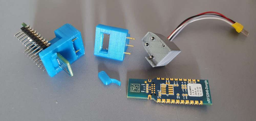
@NeverDie , you got it right, mine has the advantage of being self holding, which is quite an advantage if you want to debug, I tried, to debug in the past using the keyboard with only one hand, not very efficient :)
As you can see, the one in the left side, is holding by itself, it does not has the cables soldered though, the one on the right is my first iteration, but the side holders are weak and broke with time.
It is true that the fact of picking the two side points, it makes it self aligning.
The blue versions are the newer ones, where you can slide it in with the pogo pins stretched out, and then you press it in and lock the open space in the bottom with that small blue little thingie that we see unused and free in the middle version. So no rubber band required, all is static mechanics.
Both middle and left versions are available, the middle version requires glue to fix the pogo pins in the printed shell after being inserted the first time but makes soldering the wires on top easier. The left one has a roof holding the pogo pins but they're harder to access for soldering the debug wires in them and also printing is with slightly more debris given the complex bridging.
One way or the other, this managed to get me a self-standing pogo pin adapter of an already existing board. Indeed if you design your own, you can think of those you linked, but if you're short of space, you can also fallback on such custom 3d printed solutions.
This nRF52840 usb dongle is an amazingly powerful board and so cheap, that I'm confused why Nordic did not made the debug for it simpler, feels like they prefer to sell the dev kit for prototyping, but they don't know how hobbyist like to prototype on the final cheap product. I could afford 5 of them to experiment with some mesh protocols.So if you have access to 3d printing and would like to give it a try, I'll stay around and help if needed, also if you have improvement suggestions, I struggle with fusion360 till I get things done.
-
@NeverDie , you got it right, mine has the advantage of being self holding, which is quite an advantage if you want to debug, I tried, to debug in the past using the keyboard with only one hand, not very efficient :)
As you can see, the one in the left side, is holding by itself, it does not has the cables soldered though, the one on the right is my first iteration, but the side holders are weak and broke with time.
It is true that the fact of picking the two side points, it makes it self aligning.
The blue versions are the newer ones, where you can slide it in with the pogo pins stretched out, and then you press it in and lock the open space in the bottom with that small blue little thingie that we see unused and free in the middle version. So no rubber band required, all is static mechanics.
Both middle and left versions are available, the middle version requires glue to fix the pogo pins in the printed shell after being inserted the first time but makes soldering the wires on top easier. The left one has a roof holding the pogo pins but they're harder to access for soldering the debug wires in them and also printing is with slightly more debris given the complex bridging.
One way or the other, this managed to get me a self-standing pogo pin adapter of an already existing board. Indeed if you design your own, you can think of those you linked, but if you're short of space, you can also fallback on such custom 3d printed solutions.
This nRF52840 usb dongle is an amazingly powerful board and so cheap, that I'm confused why Nordic did not made the debug for it simpler, feels like they prefer to sell the dev kit for prototyping, but they don't know how hobbyist like to prototype on the final cheap product. I could afford 5 of them to experiment with some mesh protocols.So if you have access to 3d printing and would like to give it a try, I'll stay around and help if needed, also if you have improvement suggestions, I struggle with fusion360 till I get things done.
@wassfila Nicely engineered!
BTW, if I'm not mistaken, Adafruit's bootloader ( https://learn.adafruit.com/introducing-the-adafruit-nrf52840-feather/update-bootloader ) should work on these dongle boards as well. I suspect the way it may works is:
0. Install the booloader as per the instructions in the link above. Thereafter,- Plug the dongle into the usb port on your pc, whereupon lit's treated like a virtual hard drive.
- Drag the binary you want to upload to the virtual drive icon on the PC
- Reboot to finish, and that launches your program.
Anyone tried it? If so, is that a correct summation?
-
@wassfila Nicely engineered!
BTW, if I'm not mistaken, Adafruit's bootloader ( https://learn.adafruit.com/introducing-the-adafruit-nrf52840-feather/update-bootloader ) should work on these dongle boards as well. I suspect the way it may works is:
0. Install the booloader as per the instructions in the link above. Thereafter,- Plug the dongle into the usb port on your pc, whereupon lit's treated like a virtual hard drive.
- Drag the binary you want to upload to the virtual drive icon on the PC
- Reboot to finish, and that launches your program.
Anyone tried it? If so, is that a correct summation?
@NeverDie i can speak for arduino side im not sure how it works for CircuitPython. virtual hard drive part is only true if there was a bootloader prior to update. im not sure how nordic ships their dongles but i think they dont install adafruit bootloader inside of them :) so you need a fresh bootloader install and it is easy but you need jlink for that. after connecting your jlink to nrf52 open the arduino from menu find jlink for adafruit nrf52 and then just simply click install bootloader and voila it works with arduino.
but then again that usb dongle wont work seamlessly with adafruit bootloader because im sure adafruit has different pin maps you just need to check their pins from variants file and match them on paper to the dongle so when you write your code you know which ones to use, unless theres a seperate variants file specifically made for this dongle.