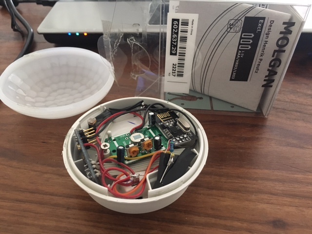
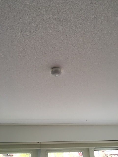
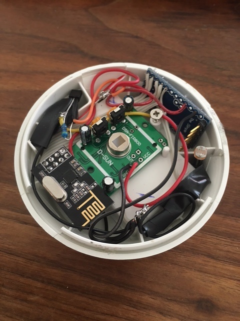
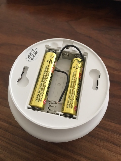
I have created a Multi sensor PIR including a dallas temp measurement and LDR light measurment. For the PIR I wanted to use the Original PIR but it got "destroyed" during my investigation. The Pir runs on two AAA as I have removed the voltage regulator on my arduino pro mini.

dynamite
Posts
-
Multisensor PIR based on IKEA Molgan -
Multisensor PIR based on IKEA Molgan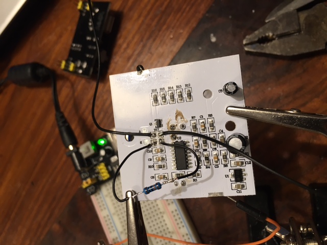
It is unfortunately not a full How-To yet. But basically the IKEA PIR is ready for operation.-
The PIR Runs on 3 Volt. There is a power regulator (U1). I am going to keep the 3 AAA batteries so I keep the regulator on the board.
-
I have removed the resistor (R17) and attached two wires to both the Original ends on the board. The one closest to the BISS0001 is your PIR signal. 3V when high and 0V for low. The other wire can be used to control the lights on the board. The wire is connected to the Q1 NPN transistor. Basically 3V high is on and 0V is off. But maybe you will also be able to dim the lights.
-
You also need to remove Resistor R11. The Original value is about 620 K and this will result in 30 seconds of ON after triggering. I have replaced it with 100 K and now it is about 5 seconds, a further reduction whill shorten this time lineair. So 10K = 0,5 sec. The PIR itself is retriggered.
-
With resistor R10 is controlling the time that the PIR cannot be triggered after a trigger. It is now approx 10K = 0,5 sec. So no need to change.
-
You need also to remove the photodiode on the front. Otherwise the PIR is only triggered when it is dark.
-
The powerconsumption of the PIR when not triggered is approx. 60 uA and when triggered 160 uA. So this is about the same as the standard PIR's. When the lights are activated the consumption is about 36 mA.
-
The PIR (without the hood) is quite sensitive. Even the slightest movement is already triggering the PIR.
-
-
Multisensor PIR based on IKEA MolganAfter I have bought some new one I will try to make a how to....
-
Multisensor PIR based on IKEA Molgan -
Multisensor PIR based on IKEA MolganI now have a fresh supply of Molgan to be modified. And I will post my modification of the existing board soon. Status I can now use the input of the existing PIR signal. And I have discovered that by sending out a high or low on one of the arduino pins I can switch the existing LED on / off. Of course I can use a relay function to control but as it is running on batteries the sensor has to sleep. I was thinking of sending out a parameter (true / false) which enables the sensor to activate the LED on a trigger of the PIR. How could I send over this parameter? Any (creative) idea's as the sensor is sleeping most of the time?
Now I am thinking of it, could it be possible that such a value is read by the sensor when the sensor is getting out of the sleep function.
-
Multisensor PIR based on IKEA Molgan@tomkxy You can change the sensitivity of the PIR. You have to change the value or R15. See here for a datasheet of the BISS001
But I do not know whether you should increase or decrease it...?
If you did not modify your PIR then the PIR will stay high for 30 SEC. What is the period between the false triggers?
Could it have to do with powering your sensebender from the powersource within the PIR and not directly from the battery? -
Gas Meter Reading Using a Magnetometer@dpcr Nice adjustment of your Original code. Based on your Original version I have started coding as well as I like the simpleness of just adding a sensor to the meter without taking care of the direct position.
My current code can be found at github via the following link:https://github.com/rspaargaren/Read_Gasmeter/blob/Workinprogress/Read_Gasmeter.ino
Basic differences are:
- I have removed the fram reference but this could be added again if you use it.
- I have added a different setup sequence for fixing the top and bottom. In my case it waits until four changes in direction have occured. So no direct gas flow have to flow after a restart.
- The number of pulses between a change in direction is fixed independent of a change in top or bottom. So in my case every half a cycle will give ten pulses and a full cycle 20 pulses.
- The results are submitted to the gateway after a intervall but also after half a cycle.
- The top and bottom is checked after each cycle. So in case of major difference the interval is changed.
- During normal run, the reading of the y value is executed within the loop. So basically the arduino has time to do some other stuff as well in between the readings.
The code is currently working but requires some clean up. Also I would like to make an option to store the values at the gateway and maybe change the hardware to an ESP version so I can have multiple ways of output. Like MQTT.
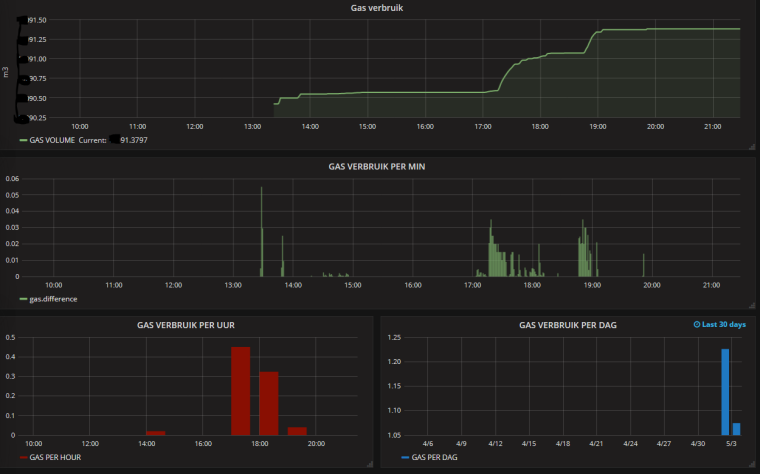
This is the current output in Grafana: