I am migrating step by step from pimatic to Hass. I still think pimatic is a lot easier to setup and to make rules, etc.. But the community behind hass is big and the ammount of items which can be controlled is huge. The mysensor part is not optimal I am using the MQTT gateway and hope some further development is made.
Posts made by dynamite
-
RE: HomeAssitant MySensors plugin Roadmap
-
RE: Multisensor PIR based on IKEA Molgan
@ricmail85 @Yveaux basically mine was shortcut by testing Some connection which I should not have Done....
-
RE: Multisensor PIR based on IKEA Molgan
@ricmail85 hi iT has been a while ago but as far as I recollect I had the same problem with one of my sensors ...
In normal situation the sensors gives a high signal for approx 30 sec.
In the bricked PIR I have replace the pir board by a cheap and modified pir from Ali.
-
RE: Gas Meter Reading Using a Magnetometer
@pihome Hi i am powering it with adapter. So no batteries used.
-
RE: Gas Meter Reading Using a Magnetometer
@Ed1500 The amplitude is quite simple it is just measuring the (max) top and (min)bottom if the direction of your signal changes.This is quite consistent during the readings and if due to temperaturen or whatever cause it is changing the max and min are adjusted. However the period / frequency of the curve is not consistent as this is directly related to the consumption.
I think the linear approach to the curve is already quite accurate. But if you have a better routine in mind I love to hear. Basically I just have to adjust the array in which the different steps are calculated.I like the idee of having a dedicated attiny as I know from my sketch that in case of high volume the changes is the y are quite fast and the is (almost) no time to communicate with the gateway etc.
-
RE: Gas Meter Reading Using a Magnetometer
@dpcr the more steps you choose of course the more accurate it gets. At this moment I have divided the Total cycle in 20 steps. I have made this a parameter in my code.
-
RE: Gas Meter Reading Using a Magnetometer
@Ed1500 The magnetometer is picking up a change in the magnetic field. Normally the sensor itself is moving and so changes in x,y and z etc can be detected. In case of the gas meter the sensor is stationary but the change in magnetic field due to the rotating magnet on the dial is detected. This will give you a snow wave.
I presume In case no magnet still small changes can be detected due to rotating parts within the meter.
-
RE: Gas Meter Reading Using a Magnetometer
@zboblamont That is a quite nice price indeed.
-
RE: Gas Meter Reading Using a Magnetometer
@jumping No I do not. Basically I use my gateway to store and retrieve the pulse value.
-
RE: Gas Meter Reading Using a Magnetometer
@dpcr Hi, I need to recalibrate to see if the reading is still OK. Somewhere during a total reset I have lost track. But it is on my to do list to get everything up and running again.
As far as I could recollect an overshoot had no influence on my code as the number of pulses for a total cycle is consistent within my code.On the Y reading from the sensor I do have a running average smoothing.
Basically every cycle is splitted into rising and falling part. Each splitted into a fixed number of steps. Based on the current reading of y the number of pulses is calculated within that step. So the amount of pulses within a rise or fall can never be more than the number of steps within that cycle.I am thinking of making the code more simple and only give a pulse on the changes and maybe one in the middle. That would give me about 4 pulses per cycle.
-
RE: Gas Meter Reading Using a Magnetometer
@jumping Hi I have used the magnetometer. (GY-282 HMC5983)
I these are the +/- of both the systems:
- More easy to locate on your gas meter
- Higher accuracy of output (more pulses per cycle)
- Code is more complex
Read Sensor
- Simple code
- Exact installation from position
- 1 puls per round
-
RE: Gas Meter Reading Using a Magnetometer
@Yveaux nice! and what code are you using? or are you referring to putting the ir sensor to the meter?
-
RE: Gas Meter Reading Using a Magnetometer
@gohan Yes i have Seen them as Well that would be the easy way out
I am just curious wether i am picking up a workable signal when i stick this sensor to it. If so it would make installation quite simple.
-
RE: Gas Meter Reading Using a Magnetometer
@dpcr Hi i am looking forward for your experience, as far as I have experienced now, and it took me quite some debugging I did not miss a pulse.
@Yveaux @dpcr My next testing is to apply this sensor for the watermeter.
-
RE: Gas Meter Reading Using a Magnetometer
@Yveaux Hi thanks for the suggestion. Basically the position I am using now gives me a very accurate signal. It is more the small changes in the Sine curve which could result in miss reading. But I have added some filtering by appying a running average.
I have tried other position just to see the results. Basically if you stick it to close to the magnet used, like the official reed position it will go in overload and magnetic reading is maximized for a period.
-
RE: Gas Meter Reading Using a Magnetometer
@dpcr Hi the reason that it is sometimes not a sine wave is the reason why I used a fixed number of pulses between the top of bottom. So in case the flow is very low as for your pilot light it will detect every puls. In case you have a very heavy flow pulses can be skipped as long as the change is detected then in my case 10 pulses are submitted to the gate way. I was detecting in your original sketch sometimes extra pulses were submitted as the sine was little bit rising or the opposite dropping.
The code for just detecting rise and fall can be quite straigh foreward. I might make a second version like that...just for the record.
My Setup is quite straight forward. A small box with the arduino pro mini and radio. A cable to the magneto sensor. In my case water proof is not required. I have applied the sensor by Velcro strap so I can remove the setup in case of "Maintenance".
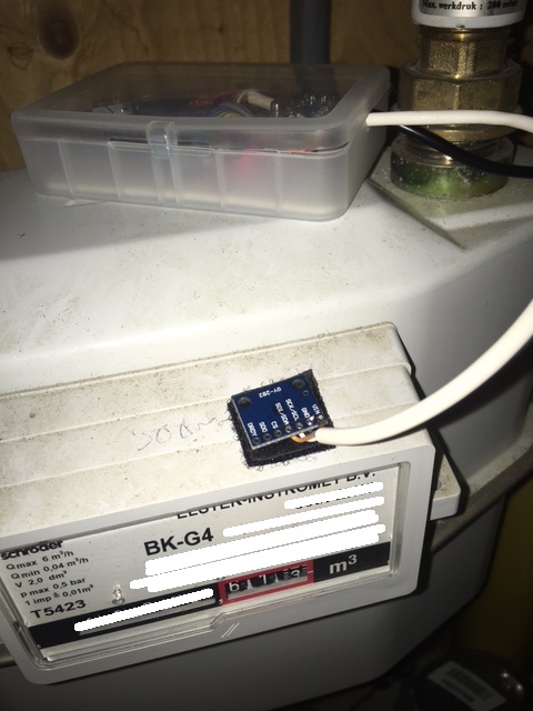
-
RE: Gas Meter Reading Using a Magnetometer
@dpcr At the moment I do not store the top and bottom value permanently. In case of a power failure I will "loose" to the max two rounds of the wheel on pulses as it uses that to calibrate the top and bottom. That could be reduced to potentially only one cycle. Which is in my case 0,01m3 to 0,02 m3 of gas indication.
After the power failure the process starts in the calibration loop which is ended only after the required cycles have registered. So this could last 30 sec in case you are having a shower but can last a week if you are away...I will post a picture of my setup later.
Now I am thinking of it. If you do not care about the accuracy that much you do not need the top and bottom values at all. You just need to detect the rice and fall. That still gives you double the accuracy than a reed contact or Hall effect. The sketch for that will be very simple and after power down you can continue most probably without loss of pulses.
-
RE: Gas Meter Reading Using a Magnetometer
@dpcr Nice adjustment of your Original code. Based on your Original version I have started coding as well as I like the simpleness of just adding a sensor to the meter without taking care of the direct position.
My current code can be found at github via the following link:https://github.com/rspaargaren/Read_Gasmeter/blob/Workinprogress/Read_Gasmeter.ino
Basic differences are:
- I have removed the fram reference but this could be added again if you use it.
- I have added a different setup sequence for fixing the top and bottom. In my case it waits until four changes in direction have occured. So no direct gas flow have to flow after a restart.
- The number of pulses between a change in direction is fixed independent of a change in top or bottom. So in my case every half a cycle will give ten pulses and a full cycle 20 pulses.
- The results are submitted to the gateway after a intervall but also after half a cycle.
- The top and bottom is checked after each cycle. So in case of major difference the interval is changed.
- During normal run, the reading of the y value is executed within the loop. So basically the arduino has time to do some other stuff as well in between the readings.
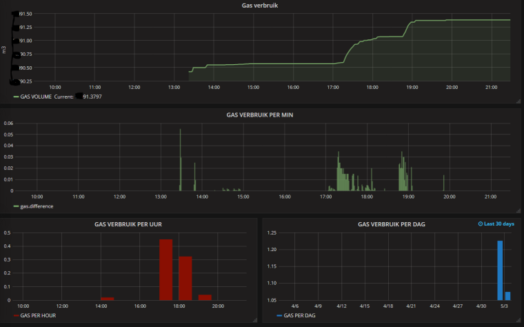
The code is currently working but requires some clean up. Also I would like to make an option to store the values at the gateway and maybe change the hardware to an ESP version so I can have multiple ways of output. Like MQTT.
This is the current output in Grafana: -
RE: Multisensor PIR based on IKEA Molgan
@gijss Hi let me check upon that as the PIR has not been on the top of my priority list. I have one of the PIR based on LDR sensor. But I was working on a BH1750 sensor. So most probably the code is related to that version.
-
RE: Multisensor PIR based on IKEA Molgan
@Yveaux great as my project was on hold for a while but still on the to do list...:-)
-
RE: Multisensor PIR based on IKEA Molgan
@dynamite , can you may be share your code and the way you have attached your LDR to the arduino etc?
@gijss the code can be found here. But I don't know the actual status of this code as I have not used it for a while and I was busy creating a dimmer. But maybe you can copy parts out of it.
https://github.com/rspaargaren/My-sensors-IKEA/blob/master/multisensor.ino
-
RE: Multisensor PIR based on IKEA Molgan
@gijss Hi I will try to find the code tonight and post it on github.
-
RE: Multisensor PIR based on IKEA Molgan
@pjblink hi your setup sounds ok to me! And from your debug I think it is transmitting a value. Is this value submitted after activating the pir?
After activation the is high for about 30 sec then it sound be low again. Maybe you can verify this procedure. Can you debug on the receiving side? -
RE: Multisensor PIR based on IKEA Molgan
@Cliff-Karlsson the receive routine is out of the repeat loop
-
RE: Multisensor PIR based on IKEA Molgan
@Cliff-Karlsson you can only use the VCC sketch if you by pass the voltage regulators. So power the arduino from two batteries by a separate wire.
-
RE: Multisensor PIR based on IKEA Molgan
@Yveaux @Cliff-Karlsson but in the scheme of cliff he is taken the power after the power regulator. So you are not
Measuring the battery with your VCC library. -
RE: Multisensor PIR based on IKEA Molgan
@tomkxy I Will put mine for a test run online tonight in the closet. If no trigger than it should be ok.
Edit: did something wrong when removing led from pro mini so some debugging is required.... No testing tonight -
RE: Multisensor PIR based on IKEA Molgan
@Yveaux @tomkxy You were one step ahead of me, I was just thinking of that solution. At the moment I am also preparing version 2 of the MOLGAN PIR based on Arduino pro Mini I will check on the false positives as well. But I will feed both the PIR and pro Mini directly from the three batteries.
-
RE: Multisensor PIR based on IKEA Molgan
@tomkxy The range of PIR is 3-5V so most probably 2.4 V will give some trouble.
-
RE: Multisensor PIR based on IKEA Molgan
@tomkxy You can change the sensitivity of the PIR. You have to change the value or R15. See here for a datasheet of the BISS001
But I do not know whether you should increase or decrease it...?
If you did not modify your PIR then the PIR will stay high for 30 SEC. What is the period between the false triggers?
Could it have to do with powering your sensebender from the powersource within the PIR and not directly from the battery? -
RE: Multisensor PIR based on IKEA Molgan
@TimO @tomkxy I have the Dallas sensor within the case. The reading follows the same line as other temp sensors within the same room. No big delay or something. The only downside is that the PIR is mounted on the roof, so temp is always a bit higher.
-
RE: Multisensor PIR based on IKEA Molgan
@korttoma As far as I can see the sensebender is fed by the 3 volt of the PIR. So you can not use this as a reference for voltage measurement.
-
RE: Multisensor PIR based on IKEA Molgan
@tomkxy Nice write up of the "conversion". One remark to save some time... instead of removing R12 to R16 you can just remove R17 ... same result less effort.
-
RE: gw.sleep on battery powered magnet door switch
@treb0r You can either wake up on the interrupt or on a time period:
bool sleep(int interrupt, int mode, unsigned long ms=0);
interrupt - Interrupt that should trigger the wakeup.
mode - RISING, FALLING, CHANGE
ms - Number of milliseconds to sleep (or 0 to sleep forever).The sleep method returns true if wake up was triggered by pin change and false means timer woke it up.
-
RE: Multisensor PIR based on IKEA Molgan
@danta
Fits.... Ok i need to attach the wites but it will still fit. The NRF can be placed on the other side -
RE: Multisensor PIR based on IKEA Molgan
@Yveaux Sent you a DM with my email adress. Can't you use the voltage level after the regulator? The regulator is rated up to 30 mA.
-
RE: Multisensor PIR based on IKEA Molgan
@Yveaux NICE! Can I get the files for the board as a sneak preview? Do you get the PIR signal / Light control from the same place as I was indicating?
-
RE: Multisensor PIR based on IKEA Molgan
It is unfortunately not a full How-To yet. But basically the IKEA PIR is ready for operation.-
The PIR Runs on 3 Volt. There is a power regulator (U1). I am going to keep the 3 AAA batteries so I keep the regulator on the board.
-
I have removed the resistor (R17) and attached two wires to both the Original ends on the board. The one closest to the BISS0001 is your PIR signal. 3V when high and 0V for low. The other wire can be used to control the lights on the board. The wire is connected to the Q1 NPN transistor. Basically 3V high is on and 0V is off. But maybe you will also be able to dim the lights.
-
You also need to remove Resistor R11. The Original value is about 620 K and this will result in 30 seconds of ON after triggering. I have replaced it with 100 K and now it is about 5 seconds, a further reduction whill shorten this time lineair. So 10K = 0,5 sec. The PIR itself is retriggered.
-
With resistor R10 is controlling the time that the PIR cannot be triggered after a trigger. It is now approx 10K = 0,5 sec. So no need to change.
-
You need also to remove the photodiode on the front. Otherwise the PIR is only triggered when it is dark.
-
The powerconsumption of the PIR when not triggered is approx. 60 uA and when triggered 160 uA. So this is about the same as the standard PIR's. When the lights are activated the consumption is about 36 mA.
-
The PIR (without the hood) is quite sensitive. Even the slightest movement is already triggering the PIR.
-
-
RE: Multisensor PIR based on IKEA Molgan
@rollercontainer I could use the wait function
/**- Wait for a specified amount of time to pass or until specified message received. Keeps process()ing.
- This does not power-down the radio nor the Arduino.
- Because this calls process() in a loop, it is a good way to wait
- in your loop() on a repeater node or sensor that listens to messages.
- @param ms Number of milliseconds to sleep.
- @param cmd Command of incoming message.
- @param msgtype Message type.
*/
void wait(unsigned long ms, uint8_t cmd, uint8_t msgtype);
And wait for a message, which is send out by the controller (by a rule) after receiving the PIR trigger. But it is a kind of waste of energy to wait for a signal which is not frequently used. As far as I can read in the code this is exactly what smart sleep does. But can how can prepare a reply by the gateway that will respond to such a heartbeat?
-
RE: Multisensor PIR based on IKEA Molgan
I now have a fresh supply of Molgan to be modified. And I will post my modification of the existing board soon. Status I can now use the input of the existing PIR signal. And I have discovered that by sending out a high or low on one of the arduino pins I can switch the existing LED on / off. Of course I can use a relay function to control but as it is running on batteries the sensor has to sleep. I was thinking of sending out a parameter (true / false) which enables the sensor to activate the LED on a trigger of the PIR. How could I send over this parameter? Any (creative) idea's as the sensor is sleeping most of the time?
Now I am thinking of it, could it be possible that such a value is read by the sensor when the sensor is getting out of the sleep function.
-
RE: Low Bat Powered 3 in 1 sensor Please Help
@AWI for my understanding in case I do keep the voltage regulator and feed my pro mini 3v with the 3 AAA of the Ikea PIR. Will it keep working even of the voltage drops to 2v. (Of course i need to change the bootloader.) can i also use the simple battery level routine? The power at the vcc will be 3v or lower even if I feed it with 3 batteries?
-
RE: Low Bat Powered 3 in 1 sensor Please Help
@rhuehn hi maybe you can have a look at this sketch. https://github.com/sweebee/Arduino-home-automation/blob/master/MySensors 1.5/Arduino/multiSensor/multiSensor.ino This had been the basis for my multisensor as Well. The battery input is directly on vcc pin. And the voltage regulator and led are disabled on the pro mini. No need to attach additional resistor for measuring battery power. You can make the interval as long as you like for sending over. Info is only submitted if the value is changed. 1 MHz is optimal for power consumption. But i have not been able
To upload the sketch in that mode. -
RE: Multisensor PIR based on IKEA Molgan
After I have bought some new one I will try to make a how to....
-
RE: Multisensor PIR based on IKEA Molgan
@Floca hi the Original Ikea Pir, I kind of destroyed during the "investigation". I my previous post I have posted a picture of the pir inside. I would feed the pir with either 2 or 3 batteries. (3/4,5v) after that you can either use the signal directly after the chip. Th is is 1,8v but I don't know if the arduino takes that as high..? If not you can take the signal at the resistors of the LEDs. The voltage level here is depending on your battery infeed. So either 3v or 4,5v. Don't think both will be a problem for the arduino. To eliminate the led you can take away one or more resistors.
Maybe somebody can say more
About the allowable Voltage levels. For battery live a 3v pro mini would be better. For ease of use a 5v version would be better -
RE: bootloader
@MarkV This is exactly the message I have received as well... Maybe check the other connection. Replace some cables? I the end I have been able to eliminate this message without changing anything in the software. In my case it was hardware related. (I was programming a pro mini and had it with two seperate mini's)
-
RE: bootloader
@MarkV Dont't know, it helped in my case. Whether it was actually the power supply is the question. But if it helps in your case as well, than most probably yes. I think it has something to do with the communication and it reads a faulty or no signature.
-
RE: bootloader
@MarkV I had this message two days ago as well. I was programming with usbasp. I have solved it by powering my pro mini with a separate power supply. So please check the cables.
-
RE: Multisensor PIR based on IKEA Molgan
@scalz @tbowmo Looking forward to see you results! Now that my prototype is finished of course I am going to buy some more as well. Here "only" €4,99 for an item
-
RE: Multisensor PIR based on IKEA Molgan
@tbowmo I think I am going to buy some IKEA shares....
-
RE: Multisensor PIR based on IKEA Molgan
@scalz What dimensions are you exactly looking for?
Here you have some photos:
-
RE: Multisensor PIR based on IKEA Molgan
@Yveaux And very easy to detach as it has a base plate as well...
-
RE: Multisensor PIR based on IKEA Molgan
@TimO Yes if have read this post too, but here he has used an optocoupler. Which is not necessary if you reduce the input to 3 volt... makes it more easy. Or even use the 1,8 volt as input. But don't short circuit it with the input pin next to it.... as the PIR will stay high forever.
-
RE: Multisensor PIR based on IKEA Molgan
So far I do not see a big difference with the Original smaller lens. Although the detection from the side is limited. But that's about the same as the Original.
Inside there is a PIR in combination with 5 leds and a photodiode. As soon as it gets dark the PIR is active and as soon as movement is detected the leds are switched on for about 30 sec.
The IKEA PIR is based on BIS0001 chip, which is a very common chip. When High it has an output of about 1,8 volt. Via a transistor the leds are switch on. Although there are three batteries in the housing the PIR runs also very well on two. (3.3 volt) -
Multisensor PIR based on IKEA Molgan
I have created a Multi sensor PIR including a dallas temp measurement and LDR light measurment. For the PIR I wanted to use the Original PIR but it got "destroyed" during my investigation. The Pir runs on two AAA as I have removed the voltage regulator on my arduino pro mini.