Jmarcusse
Posts
-
Supply 230V/5V for node ? Mini Pro, NRF24L01, ams1117 -
Supply 230V/5V for node ? Mini Pro, NRF24L01, ams1117Responses :
-
Supplied by USB:
Vcc Usb = 5,01V ; Vcc MiniPro = 4,59V ; RAW MiniPro = 4,59V ; NRF = 3,28V -
Supplied by 230V module Onboard :
Vcc Usb = -1,97V !!! ; Vcc MiniPro = 4,98V ; RAW MiniPro = 4,989V ; NRF = 3,29V -
Supplied by 230V module Out of PCB, far at 95cm, 5V and 0V twisted between module and PCB :
Vcc Usb = -0,30V !!! ; Vcc MiniPro = 4,95V ; RAW MiniPro = 4,95V ; NRF = 3,29V
And I can tell you a real good new : all is correct when module is far....
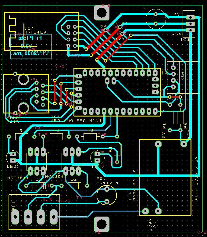
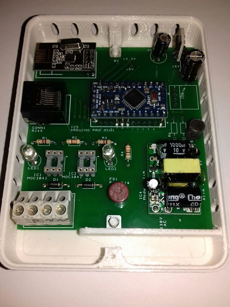
When I approach the module on its place on PCB, leds are not drived correctly, probleme is coming!!! When module is distanced in up from PCB (6 à 8mm), all is good. So, I have now to try to redesign PCB for trace the ground in other direction, sure not under transformer of the module.
I can say you good thanks, if you not help me, I cannot run heaters.. Really thanks, and I wish you a Merry Chrismas as possible this year. Best regards. -
-
Supply 230V/5V for node ? Mini Pro, NRF24L01, ams1117I remember normal Vcc is a bit different (-0,2V) than FTDI 5v from PC. I can measure it really.
I have to test with battery, to mesure the difference between twice 5V.
The ProMinis provide from Chine by Ebay, no drawing come with. I could try to ask but I'm not sure get a response...
Good idea to externalise the module from PCB, I have other, easy to do. I have to test it too !!! -
Supply 230V/5V for node ? Mini Pro, NRF24L01, ams1117Yes I design myself. Your opinion for the ground traces near 230V are corrects.
I'm agree to modify a PCB cutting traces to be as far as possible to test result. (I have 10 PCBs for only 7 will used).
Of course I make test with scope, 5V in all the PCB is a bit noised (100 mV~, 150mV~), with pics a the cutting frequence of supply of course.For the internaly drawing of MiniPRo you send me, I don't very understand where is connected the Vcc of FTDI Basic JP1. Does we understand all is named "Vcc" are the same Vcc?
Do you think I have to shunt my 2 differents Vcc? will burn or not burn....I will tell you result as soon as possible. Thanks you very much EVB, Cabat; it's very pleasant to me to receive your help.
-
Supply 230V/5V for node ? Mini Pro, NRF24L01, ams1117

-
Supply 230V/5V for node ? Mini Pro, NRF24L01, ams1117We are speaking about 5V MiniPro version.
First I use the Vcc pin, yes. But I test with RAW and its regulator on board, but 5v is too low to work correctly I know. But MiniPro run in both.
I take a MiniPRo just arrived (open satchel plastic), out off voltage, the 2 Vcc pins are not connected, sure : 85ko between both, or10,4Mo if I reverse ohmeter... I test it in the minute.
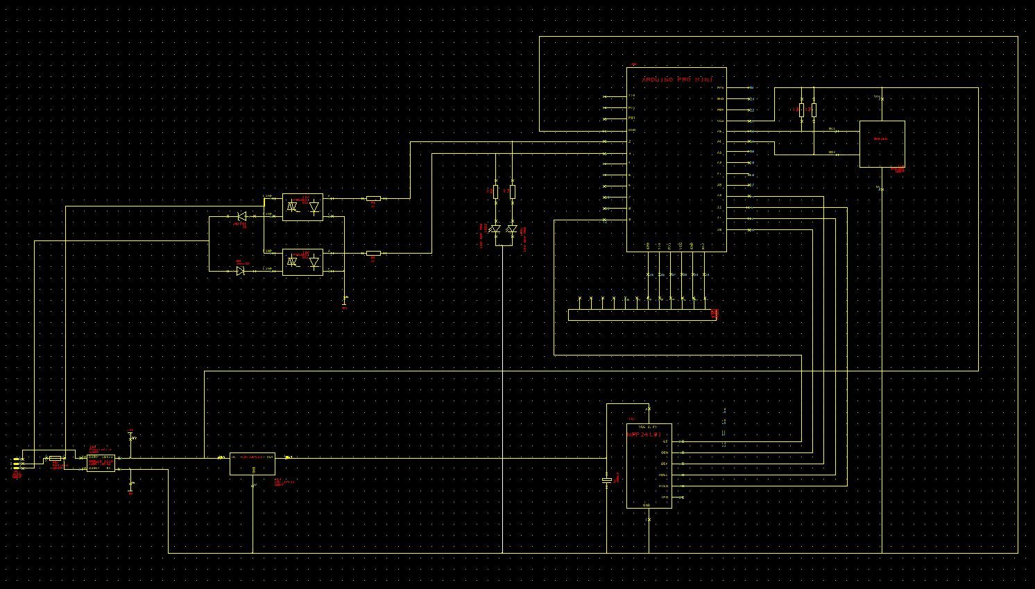
Yes I send the drawing and PCB because difficulty to read pin numbers on drawing.
I verify supply 5v, supply .3V, grounds. The 3 grounds of MiniPro are internally connected. I use only the GND pin face Vcc.
I have 4 nodes, all same problems.
Battery was on normal Vcc pin.The difference of supplies USB/ module Onboard give problem, sure.
Other important things : I put a BME280 inside 3 other same nodes installed directly inside heaters (modules 230V/5V onboard supplies all the PCB (no connexion USB) : all the temperature, pression, humidity go to Domoticz with no errors.
This mean : MiniPro reading BME280, calculations, emission by NRF, all is correct.
This mean too : reception by NRF is not correct to drive 2 signals for pilot heater, but only when I supply with onboard module.But soft is working well with USB connexion, so no soft problems...
By acquiescence, I reassembled the same assembly on an Arduino UNO board, and the problem is exactly the same.
-
Supply 230V/5V for node ? Mini Pro, NRF24L01, ams1117The convertor is a bought on, only 100 mV noise, not so bad.
-
Supply 230V/5V for node ? Mini Pro, NRF24L01, ams1117Thanks for your responses.
MiniPro is running correctly, program Blink is able to manage pin 2 and 3 and activate leds.
With a MySensors Node programme, all is good, and correctly activate when FTDI card is used, Rx and Tx send debbug messages all is correct, Domoticz manage correctlty the node, and drive the 2 leds as wanted.
Problem come as soon as I connect the 230V / 5V module on board : leds are not drived correctly, sometime one is not activate, or desactivate. Only 10% drived correctly.So my test this afternoon :
If supplying MiniPro by PC via USB and FDTI card provide a good situation, I try to send MY supply (module 230V/5V) to the Vcc pin used by PC (not the legal Vcc input, not the RAW pin) : it's better, 95% drived correctly.Vcc pin for serial, and Vcc pin ProMini are not the same, not relation with ohmeter...
For connecting earth, I haven't near my heaters. I can try on table to see what's happen.
I will continue, I have to soluce. Best regards.
-
Supply 230V/5V for node ? Mini Pro, NRF24L01, ams1117Hello,
A problem on which I dry.

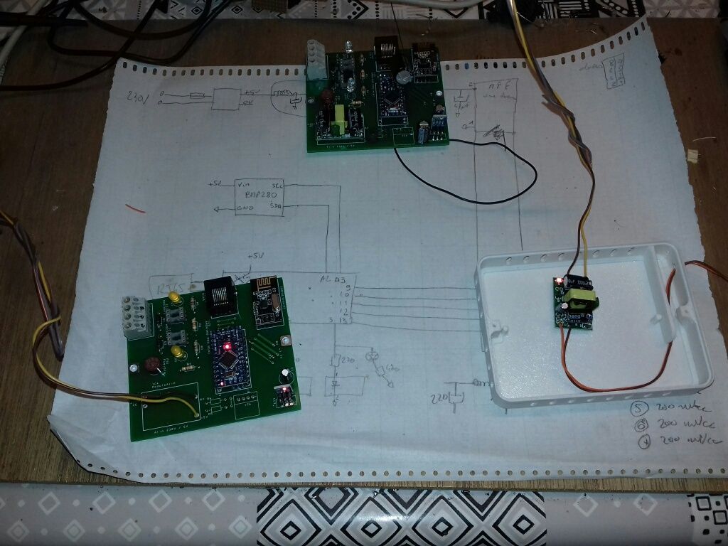
I mounted a node to control my radiators in 4-order pilot wire, Arduino MiniPro + radio NRF24L01, connected to a usb - raspberry gateway (domoticz 2020.1). The gateway works well for other nodes.
The node-gateway-domoticz link works very well when the node is powered by usb from a usb of the PC or even from a battery (power bank).
the domoticz log goes back to the node identification at init:The same node does not send any information to the gateway when I connect it to an onboard! 230V / 5V power supply
I tested with or without the 10µ 47µ condo on the 3.3V power supply built by an AM1114 regulator from 5V. Nothing to do.By acquiescence, I reassembled the same assembly on an Arduino UNO board, and the problem is exactly the same.
I therefore exclude a software problem, it is rather related to the hard, to the masses?
Who has ever mounted an NRF on a mains powered assembly?
It's a shame because I have 230V behind each radiator, and my 8 boxes are ready to send the signal on the pilot wires.
I therefore take any lead because I am at a dead end ... Thank you for your insight!
