Supply 230V/5V for node ? Mini Pro, NRF24L01, ams1117
-
Hello,
A problem on which I dry.
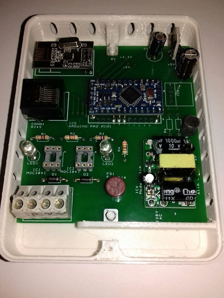
I mounted a node to control my radiators in 4-order pilot wire, Arduino MiniPro + radio NRF24L01, connected to a usb - raspberry gateway (domoticz 2020.1). The gateway works well for other nodes.
The node-gateway-domoticz link works very well when the node is powered by usb from a usb of the PC or even from a battery (power bank).
the domoticz log goes back to the node identification at init:The same node does not send any information to the gateway when I connect it to an onboard! 230V / 5V power supply
I tested with or without the 10µ 47µ condo on the 3.3V power supply built by an AM1114 regulator from 5V. Nothing to do.By acquiescence, I reassembled the same assembly on an Arduino UNO board, and the problem is exactly the same.
I therefore exclude a software problem, it is rather related to the hard, to the masses?
Who has ever mounted an NRF on a mains powered assembly?
It's a shame because I have 230V behind each radiator, and my 8 boxes are ready to send the signal on the pilot wires.
I therefore take any lead because I am at a dead end ... Thank you for your insight!
-
@Jmarcusse, I imagine that you measured, with the 220V connected, everywhere the 5V and 3.3V and that they are all correct.
I'm seeing a custom PCB, so I imagine you are aware of the risks of working directly with 220V AC ;-)Then I should do following debugging workflow:
-
Verify if the pro mini is running correctly : connect the pro mini via your ttl to usb cable to the laptop and look at the debug messages. Is the pro mini sending his radio messages?
With extra debug serial prints in your sketch, you can verify if the program is running correctly. -
The convertor circuit to make 5V and 3.3V from 220V AC is maybe producing to much noise.
So two tests we can do:
First test: try to put a metallic shield between the AC part of the PCB and the radio. Connect the metallic plate to the earth of the 220V. But pay a very high attention for short-circuits by error, especially if there are bare contact points at the 220V level on the PCB!!!!
Second test: deconnect your NRF24LO1 from the PCB and reconnect the radio with wires to move the radio further away from the AC power. Of course make these wires not too long, because they can act as antenna's, making it even worse.
It is maybe easier to do directly the second test with an external shield outside the plastic box...
Is this convertor circuit your own design of a bought one?
-
-
Thanks for your responses.
MiniPro is running correctly, program Blink is able to manage pin 2 and 3 and activate leds.
With a MySensors Node programme, all is good, and correctly activate when FTDI card is used, Rx and Tx send debbug messages all is correct, Domoticz manage correctlty the node, and drive the 2 leds as wanted.
Problem come as soon as I connect the 230V / 5V module on board : leds are not drived correctly, sometime one is not activate, or desactivate. Only 10% drived correctly.So my test this afternoon :
If supplying MiniPro by PC via USB and FDTI card provide a good situation, I try to send MY supply (module 230V/5V) to the Vcc pin used by PC (not the legal Vcc input, not the RAW pin) : it's better, 95% drived correctly.Vcc pin for serial, and Vcc pin ProMini are not the same, not relation with ohmeter...
For connecting earth, I haven't near my heaters. I can try on table to see what's happen.
I will continue, I have to soluce. Best regards.
-
Are we speaking about a 5V pro mini or a 3.3V pro mini?
- In case of a 5V pro mini, are you connecting the 5V output of the 220V AC power board to the VCC pin or to the RAW pin? It should be the VCC pin if you have 5V.
The RAW pin is connected to the voltage regulator of the pro mini and should be between 6V and 12V)
The VCC pin on the FTDI header and the normal VCC pin are connected together in my version of pro mini boards. Are you saying that this is not the case with your board?
- in case of a 3.3V pro mini, you must connect the 5V to the RAW pin or connect the 3.3V from the ams1117 to the VCC pin on the pro mini.
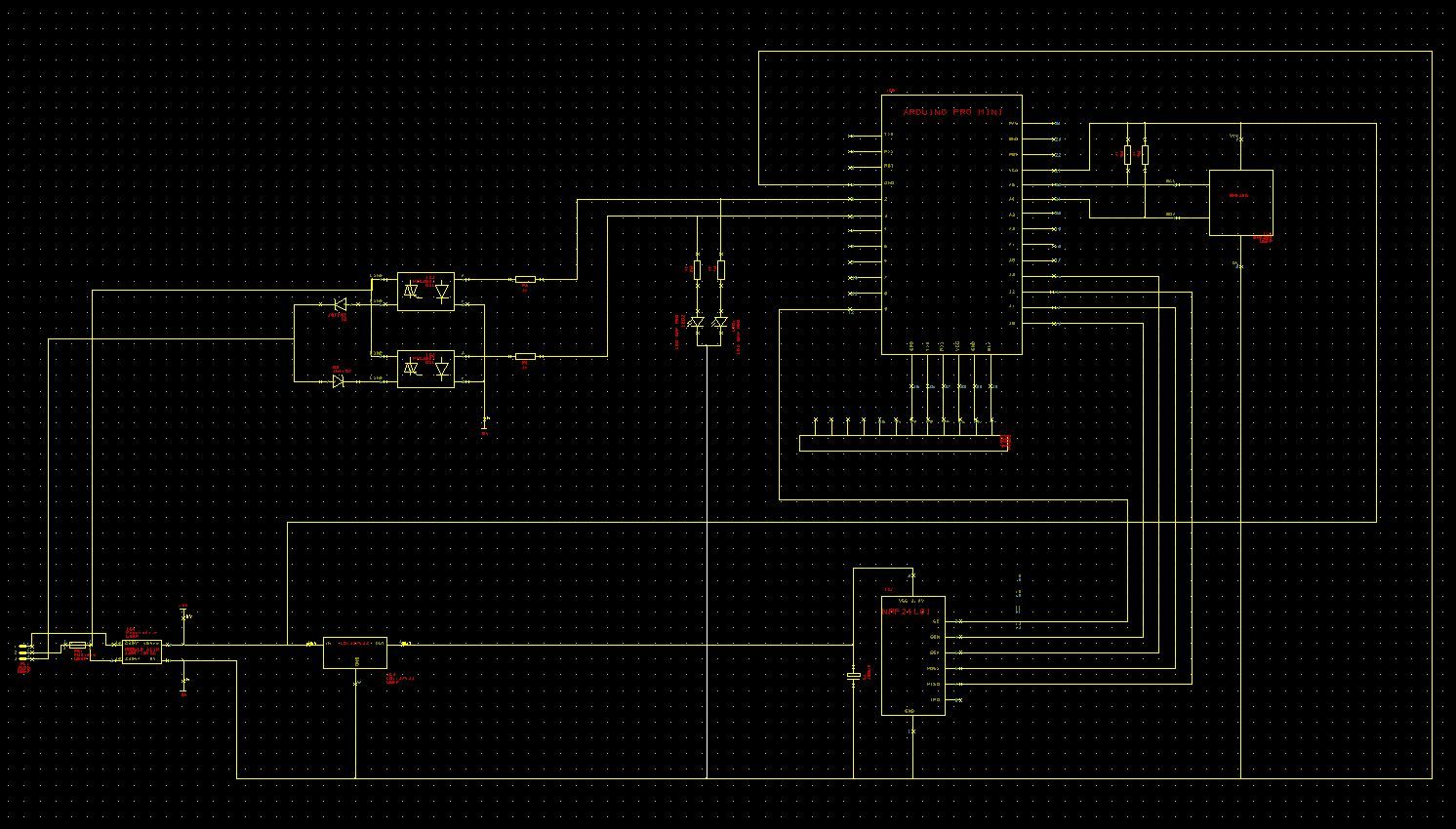
Do you have an electronic schema?
Did you verify the soldered connections between the power supply and the pro mini? And the ground connections?
Did you try with another pro mini?
When you tried with the battery pack, was it connected to the FTDI VCC header pin or the normal VCC pin? - In case of a 5V pro mini, are you connecting the 5V output of the 220V AC power board to the VCC pin or to the RAW pin? It should be the VCC pin if you have 5V.
-
We are speaking about 5V MiniPro version.
First I use the Vcc pin, yes. But I test with RAW and its regulator on board, but 5v is too low to work correctly I know. But MiniPro run in both.
I take a MiniPRo just arrived (open satchel plastic), out off voltage, the 2 Vcc pins are not connected, sure : 85ko between both, or10,4Mo if I reverse ohmeter... I test it in the minute.
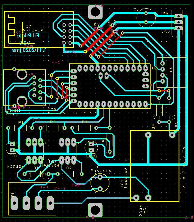
Yes I send the drawing and PCB because difficulty to read pin numbers on drawing.
I verify supply 5v, supply .3V, grounds. The 3 grounds of MiniPro are internally connected. I use only the GND pin face Vcc.
I have 4 nodes, all same problems.
Battery was on normal Vcc pin.The difference of supplies USB/ module Onboard give problem, sure.
Other important things : I put a BME280 inside 3 other same nodes installed directly inside heaters (modules 230V/5V onboard supplies all the PCB (no connexion USB) : all the temperature, pression, humidity go to Domoticz with no errors.
This mean : MiniPro reading BME280, calculations, emission by NRF, all is correct.
This mean too : reception by NRF is not correct to drive 2 signals for pilot heater, but only when I supply with onboard module.But soft is working well with USB connexion, so no soft problems...
By acquiescence, I reassembled the same assembly on an Arduino UNO board, and the problem is exactly the same.
-
@Jmarcusse said in Supply 230V/5V for node ? Mini Pro, NRF24L01, ams1117:
I take a MiniPRo just arrived (open satchel plastic), out off voltage, the 2 Vcc pins are not connected, sure : 85ko between both, or10,4Mo if I reverse ohmeter... I test it in the minute.
Strange, mine are giving 0 ohm between them. It should be 0 ohm.
But let's resume the tests:
- pro mini powered by USB via FTDI header: working --> the onboard AC power convertor not connected and we use the VCC pin of the FTDI header: the leds are working so the pro mini sketch is correctly working.
- pro mini powered by battery pack : working --> the onboard AC power convertor not connected and we use the normal VCC pin of the pro mini: the leds are working so the pro mini sketch is correctly working.
- pro mini powered by the onboard AC power convertor : not working --> is using the normal VCC pin of the pro mini
Did you design this pcb yourself?
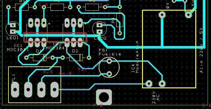
I see the GND print trace going near the AC print traces and under the AC power convertor.
I'm not a PCB specialist, but just using common logic sense, for me high voltage AC print traces and low voltage print traces should be as far apart as possible.Do you have a scoop to see the 5V signal when powered by USB and powered by the onboard AC power convertor?
-
Yes I design myself. Your opinion for the ground traces near 230V are corrects.
I'm agree to modify a PCB cutting traces to be as far as possible to test result. (I have 10 PCBs for only 7 will used).
Of course I make test with scope, 5V in all the PCB is a bit noised (100 mV~, 150mV~), with pics a the cutting frequence of supply of course.For the internaly drawing of MiniPRo you send me, I don't very understand where is connected the Vcc of FTDI Basic JP1. Does we understand all is named "Vcc" are the same Vcc?
Do you think I have to shunt my 2 differents Vcc? will burn or not burn....I will tell you result as soon as possible. Thanks you very much EVB, Cabat; it's very pleasant to me to receive your help.
-
@Jmarcusse said in Supply 230V/5V for node ? Mini Pro, NRF24L01, ams1117:
For the internaly drawing of MiniPRo you send me, I don't very understand where is connected the Vcc of FTDI Basic JP1. Does we understand all is named "Vcc" are the same Vcc?
Do you think I have to shunt my 2 differents Vcc? will burn or not burn....Normally it is the same VCC.
We can test it. If you connect your USB to FTDI cable, do you measure 5V on the normal VCC?
And the opposite: connect the batterypack to the normal VCC and measure the VCC on the FTDI header?
Where did you buy these pro mini's? Do they have a schematic?
Don't shunt them without knowing the schematic, because you can burn something!Another test you can do, but be very carefull because you are working with 220V AC!!!!!
If you have a spare part of the bought AC power PCB module, connect it not on the PCB you designed, but use it separately next to your PCB (let's say 30cm away) and connect only the GND and 5V to your PCB.
If that is working, you are 100% sure that the current 220V AC design on your PCB is the problem. -
I remember normal Vcc is a bit different (-0,2V) than FTDI 5v from PC. I can measure it really.
I have to test with battery, to mesure the difference between twice 5V.
The ProMinis provide from Chine by Ebay, no drawing come with. I could try to ask but I'm not sure get a response...
Good idea to externalise the module from PCB, I have other, easy to do. I have to test it too !!! -
Responses :
-
Supplied by USB:
Vcc Usb = 5,01V ; Vcc MiniPro = 4,59V ; RAW MiniPro = 4,59V ; NRF = 3,28V -
Supplied by 230V module Onboard :
Vcc Usb = -1,97V !!! ; Vcc MiniPro = 4,98V ; RAW MiniPro = 4,989V ; NRF = 3,29V -
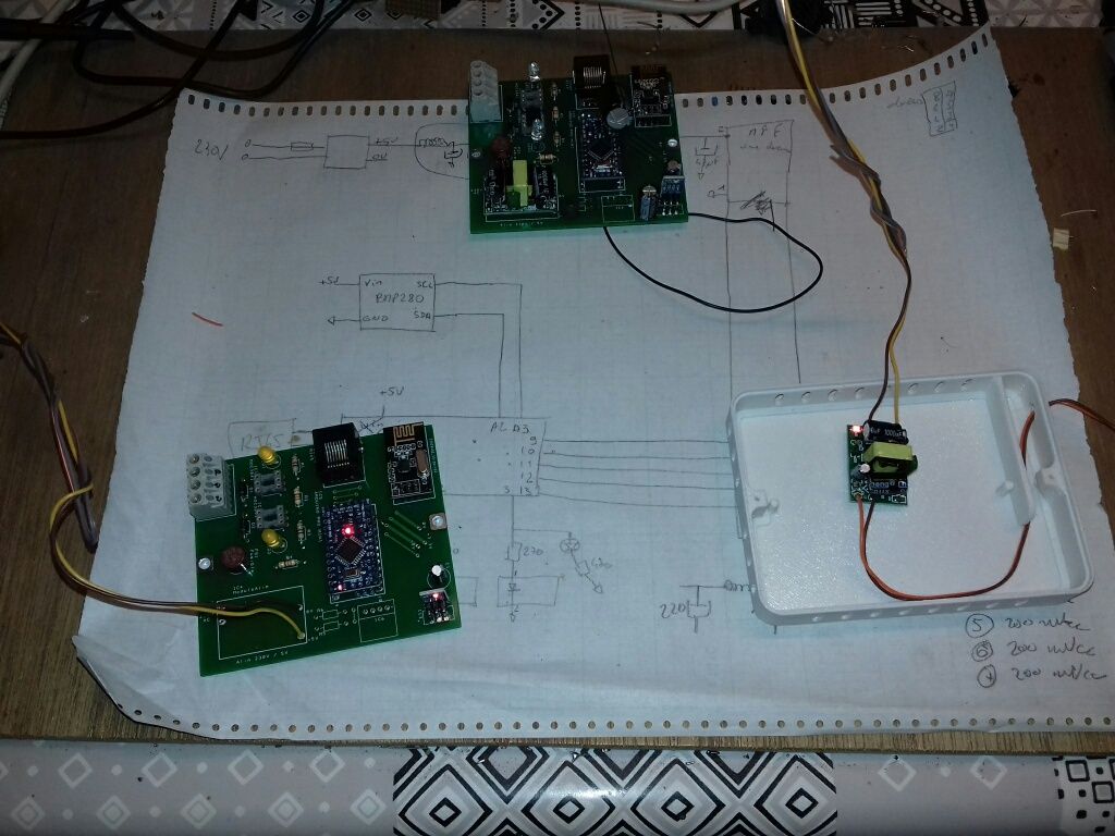
Supplied by 230V module Out of PCB, far at 95cm, 5V and 0V twisted between module and PCB :
Vcc Usb = -0,30V !!! ; Vcc MiniPro = 4,95V ; RAW MiniPro = 4,95V ; NRF = 3,29V
And I can tell you a real good new : all is correct when module is far....
When I approach the module on its place on PCB, leds are not drived correctly, probleme is coming!!! When module is distanced in up from PCB (6 à 8mm), all is good. So, I have now to try to redesign PCB for trace the ground in other direction, sure not under transformer of the module.
I can say you good thanks, if you not help me, I cannot run heaters.. Really thanks, and I wish you a Merry Chrismas as possible this year. Best regards. -
-
@Jmarcusse, glad to be of any help :-)
I would recommend searching the internet for PCB design tips on how to deal with the high dangerous voltage 220V and the low voltage of 5V on one PCB.
I know for sure that there are technical requirements in terms of distance between print tracks when working with 220V.Maybe other members can give tips here or links to documentation?
In the Openhardware.io section you can find designs of members working with 220V on their nodes: search for '220V'.
It can be a base to correct your design.Please report back if you have a new working design :-)
Merry christmas and happy new year. -
@Jmarcusse, glad to be of any help :-)
I would recommend searching the internet for PCB design tips on how to deal with the high dangerous voltage 220V and the low voltage of 5V on one PCB.
I know for sure that there are technical requirements in terms of distance between print tracks when working with 220V.Maybe other members can give tips here or links to documentation?
In the Openhardware.io section you can find designs of members working with 220V on their nodes: search for '220V'.
It can be a base to correct your design.Please report back if you have a new working design :-)
Merry christmas and happy new year.@evb The last 2 photos on this thread show those cheap crappy Chinese power converters that wouldn't likely pass electrical safety checks in many countries (they can get away with it as it is not a finished product and is not subject to electrical safety inspection in your country before you get it).
Power supplies are not an area you want to scrimp on!
Make sure that they are properly isolated with a large gap (preferably an air gap) for the high voltage side along with fuses, filters and mov's.
The most important things with power is safety (your life and other peoples).
Fire risk (would your home insurance pay out if one of these was found to be the cause of a fire?).
Heat. All power converters generate heat of some sort. It needs to go somewhere or the life of the components will be shortened and the risk of fire increases.
Lets also not forget that the fewer components on a power board will usually make the output electrically 'noisier' and can cause thier own problems with the radio side of things or other equipment. -
@Jmarcusse, I agree totally with @skywatch
That's the reason why I use a simple power adapter where it is possible. For example an USB power adapter from an old smarthphone or adapter from a known manufacturer like the PSSE0910BN from Velleman (very well know in Belgium). The latter are more expensive, but safer!If you still want to incorporate the 220V convertor module in your design, consider the proposal of @skywatch ==> an air gap between them ==> make two PCB's, one with only the 220V power module and one with the low voltage components...
-
@Jmarcusse, I agree totally with @skywatch
That's the reason why I use a simple power adapter where it is possible. For example an USB power adapter from an old smarthphone or adapter from a known manufacturer like the PSSE0910BN from Velleman (very well know in Belgium). The latter are more expensive, but safer!If you still want to incorporate the 220V convertor module in your design, consider the proposal of @skywatch ==> an air gap between them ==> make two PCB's, one with only the 220V power module and one with the low voltage components...
@evb An air gap can be a slot cut out of the pcb around the live/neutral/earth and also between the high voltage side and the low voltage side. It helps reduce 'flash over' in the event of a surge, nearby lightning strike or even humid conditions.
I have a collection of power supplies from China that I simply won't use due to safety concerns.
I even once bought some 'finished' (in a sealed case) 12v power supplies. I ordered 4 of them. All had the same markings, same case, same CE logo.
Opening them up I find 3 different boards that had been chopped out of other equipment (with the original 240V input wires twisted and simply cut off and left flaping around in the breeze. I had to do some work on them before I'd even plug them in!!!
Also, be warned that there are plenty of fake/counterfeit power supplies out there.
-
Hello,
A problem on which I dry.
I mounted a node to control my radiators in 4-order pilot wire, Arduino MiniPro + radio NRF24L01, connected to a usb - raspberry gateway (domoticz 2020.1). The gateway works well for other nodes.
The node-gateway-domoticz link works very well when the node is powered by usb from a usb of the PC or even from a battery (power bank).
the domoticz log goes back to the node identification at init:The same node does not send any information to the gateway when I connect it to an onboard! 230V / 5V power supply
I tested with or without the 10µ 47µ condo on the 3.3V power supply built by an AM1114 regulator from 5V. Nothing to do.By acquiescence, I reassembled the same assembly on an Arduino UNO board, and the problem is exactly the same.
I therefore exclude a software problem, it is rather related to the hard, to the masses?
Who has ever mounted an NRF on a mains powered assembly?
It's a shame because I have 230V behind each radiator, and my 8 boxes are ready to send the signal on the pilot wires.
I therefore take any lead because I am at a dead end ... Thank you for your insight!
-
@Jmarcusse
ON my side i do use many modules over 230 AC power without difficulties, but i'm always using Hi-Link modules for either 5v or 3.3v. I'm using different Arduino flavors (SAMD, NRF52, ...) no issues
Hello! It looks like you're interested in this conversation, but you don't have an account yet.
Getting fed up of having to scroll through the same posts each visit? When you register for an account, you'll always come back to exactly where you were before, and choose to be notified of new replies (either via email, or push notification). You'll also be able to save bookmarks and upvote posts to show your appreciation to other community members.
With your input, this post could be even better 💗
Register Login