Navigation

    • Register
    • Login
    • OpenHardware.io
    • Categories
    • Recent
    • Tags
    • Popular
    1. Home
    2. Mathea90
    3. Best
    • Profile
    • Following
    • Followers
    • Topics
    • Posts
    • Best
    • Groups

    Best posts made by Mathea90

    • Build a reliable power supply chain

      Hi guys,
      I'm writing this not because I have a problem but because I was finally able to solve some. I think it's worthwhile posting my experience here to maybe help some of you.

      For a long time I was experiencing random unreliable radio communications with NRF24L01+ nodes powered by power adaptors. Some of my nodes worked perfectly while some others were receiving data really inreliably and generally had problems communicating. After a lot of try and error and reading some tips I think I have now found a reliable solution: Power supply input filtering.

      I knew for a long time that the transceivers we use are highly sensitive to the cleanliness of their power supply and that typical cheap AC / DC switching power supplies (like e.g. a 5V phone charger) produces pretty noisy DC. But due to lack of an oscilloscope I didn't really know what to do about that.

      After I've read this awesome post I tried putting such a recommended LC filter between the output of my LDO and the transceiver to clean out the power supplied to the transceiver. Unfortunately it didn't really work and I still had the same problems. After a lot of trying and playing around I have developed the theory that some linear power regulators are very pedantic about their output capacitors (specifically their respective ESR values) and you have to be really careful about what to put on the output of those things. I also learned that LC filter design is not as trivial as I thought: In bad case scenarios such a filter can start to oscillate and make things worse. So if you don't really know what you're doing and don't have an oscilloscope it is difficult to accurately design a working filter.

      So my proposed solution is the following: Put such an LC filter directly between the output of your AC/DC power brick and the input of the power regulator. Linear LDO regulators typically already output pretty clean DC voltage, but only if their input is also kinda clean. The parameter that describes this correlation is called the "PSRR" or "power supply ripple rejection". In other words: shit in --> little less shit out.

      By putting an LC filter (or Pi filter, whaterver) in front of the power regulator you are pre-filtering most of the bad output ripple of the cheap AliExpress 5V phone chargers and other power bricks. This "kinda clean" voltage is then supplied to the LDO which can do the rest of the work and filter out the remaining ripple or oscillation.

      I don't know if my description is absolutely accurate and if it is the best solution that also a professional electronics design engineer would choose but at least for me it was the first thing that really worked.

      In the end my proposed "optimal" (in respect to complexity vs. benefit) power chain can look like this:
      0_1533288566746_Power Supply Design Update.JPG

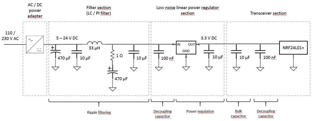
      I don't know if the capacitor and inductor sizes are optimal, but something approximately to this is running flawlessly in my home on several nodes. As an LDO I have been successful with the MIC5205 (same as Arduino Pro Mini), AMS1117, MCP1700, LE33 and LP2950 (this was the one I initially had the most problems with).

      Also if you want to use such a design, keep the components of the individual sections as close as possible together. Between the blocks you can (within reason) do what you want, but you will get the highest quality out of short distances within the sections.

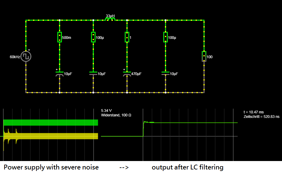
      edit: I played around with different filter values in circuitjs and updated some things in the proposed circuit diagram. I decreased the inductor size from 333uF to 33uF (Low-pass cutoff frequency is higher but should be sufficient for AC adapters with a switching frequency higher than ~60kHz) and roughly doubled the size of the LC filter capacitor. Also I implemented a damping resistor (1 ohm resistor in series with 470uF capacitor) to optimize the behavior. Here you can see the result:

      0_1533288827048_LC Filter.png

      posted in Troubleshooting
      Mathea90
      Mathea90
    • RE: [SOLVED] Very Bad Receiving Performance of Node when Powered by Buck Converter

      Guys, I found a solution for my problem! I tried everything from soldering the two GND pins of the Arduino together to an additional small condenser but nothing worked.

      So just for the heck of it I connected my buck converter to the RAW pin of the Arduino and adjusted it to something between 3,5 and 4V. Now my stepper driver and the transceiver both are supplied with power from the Arduino VCC pin and it works 100% reliable. So my conclusion is that the Step down converter of the Arduino conditions the 3.3V better than the buck Converter and this solved all my receiving problems.

      I don't like that I now have an additional conversion step in my power supply but honestly at this moment I don't bother anymore because I'm just happy to have it finally working.

      I thank you all very much for your Input!

      posted in Troubleshooting
      Mathea90
      Mathea90
    • RE: Introductions and Range Issues

      @titvs said in Introductions and Range Issues:

      I was wondering if its ok to set the MY_RF24_PA_LEVEL to HIGH on all powered nodes (sensors, repeater and gateway), or the performance will be degraded?

      Talking about the frequency ranges, i have a mesh of wifi Ubiquiti Unifi AP's in my house, which are able to do a RF scan and show me the channels that are more utilized. It seems the more crowded channels here are (20 MHz): 5 (2421-2443), 6 (2431-2453 MHz), and (40 MHz): 3 (2401-2443), 5 (2411-2453) and 9 (2431-2473).
      With this in mind, im setting up my nodes on channel 2 (MY_RF24_CHANNEL 1 if im correct) where there is 0% utilization.

      Hi titvs,

      • I can remember that initially the MySensors library set the NRF24L01s power to "HIGH" by default. I just glanced at the API page to verify if this is still the case but it seems that now the default value has been set to "MAX" which is the highest possible power setting. In my experience if you know that you have enough supply power for the transceiver (in my case it even works with 100 mA 3.3V regulators) you can set the power "MAX" without a problem. In my case it increased the range a little bit and did not decrease the network quality. But keep in mind that the PA version of the NRF24L01 (the version with the power amplifier and large external antenna) is using significantly more power. So I assume you need a power source that can handle approximately >200 mA or even more.

      • I personally would just leave the MySensors network on its default channel. In the USA this channel is already out of the range of wifi. In Europe you theoretically could have an overlap but I personally have not experienced problems with this. IMO the problem with using lower channels is that wifi routers set to automatically search for the best channel could choose to just hop on your precious MySensors channel. Then your effors was just a waste of time and you have to manually change the firmware on every MySensors device again. If you use the MYSBootloader to flash FOTA updates, you are tied to use the default channel anyways.

      --> Just to follow up on my previous post with my quality and reliability problems of the NRF24L01 transceivers: I think I was able to solve the problem as now my communication has been running flawlessly for over two days. The trick that seemed to work was to decouple the whole device from its power source input as much as possible by using an LC filter before going into the 3.3V LDO that supplies my transceivers. Previously I tried out everything to clean up the power supply AFTER the step down converter (also tried RC, LC filters, various capacitors...) but it didn't work reliably. I assume the problem with this is that some power regulators are absolutely pedantic about the ESR of their output capacitors. Playing around with various filter configurations on the output of the regulator maybe screwed up those values and caused the regulator to be unstable. Also I have no idea what I'm doing when I'm "designing" those filters, so I just randomly tried out various combinations of inductors and capacitors. So maybe this also caused more harm than good.

      But now by putting the LC filter in between the output of the switching power adapter and the input of the LDO and keeping the output capacitors of the regulator exactly as specified in the data sheet, it basically solves all those problems. Basically the LDO doesn't care at all about the ESR or capacitor values at its input and also the chance that a badly designed LC filter is causing problems is much lower as the power regulator can dampen those influences afterwards.

      So in my experience this configuration can solve most problems of bad communication due to dirty power supplies:

      120V / 230V AC Mains --> Switching power adapter (5 - 24V DC with loads of ripple) --> LC / PI Filter (less ripple) --> linear LDO power regulator with output capacitors as specified in data sheet (clean 3.3V DC) --> NRF24L01+

      posted in Troubleshooting
      Mathea90
      Mathea90
    • RE: Question about capacitor

      That's a good question. I assume that you have used an electrolytic capacitor, right? If it would have been a ceramic type: no worries, they don't have a polarity.
      The answers I could find in the internet for electrolytic capacitors varied quite a bit, but the consensus seems to be that they like to blow up in such cases, provided a high enough voltage. So I have two theories why yours didn't: either you have used a capacitor rated for a higher voltage and the 3.3V wasn't enough to destruct it. Or the current through the capacitor was limited because the 3.3V regulator could not provide more.

      Anyways I have read that you should replace such a capacitor that has been subjected to a reverse polarity to be sure because it could have taken long-term damage.

      posted in Troubleshooting
      Mathea90
      Mathea90