Hi everyone,
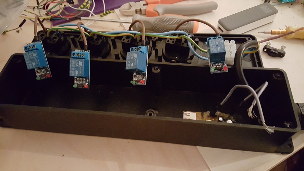
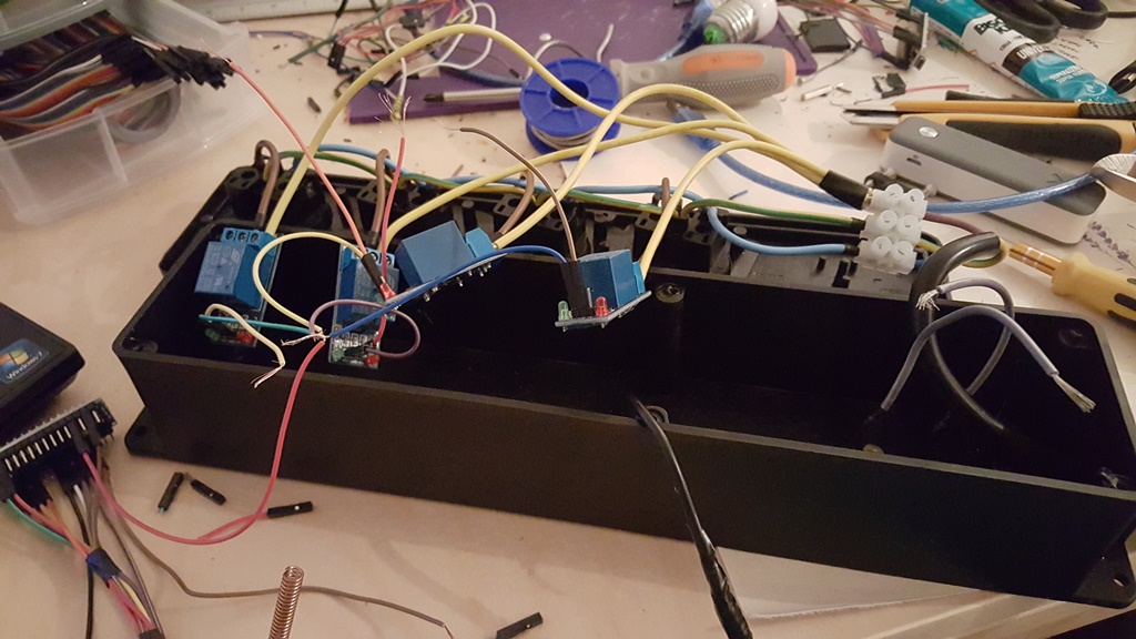
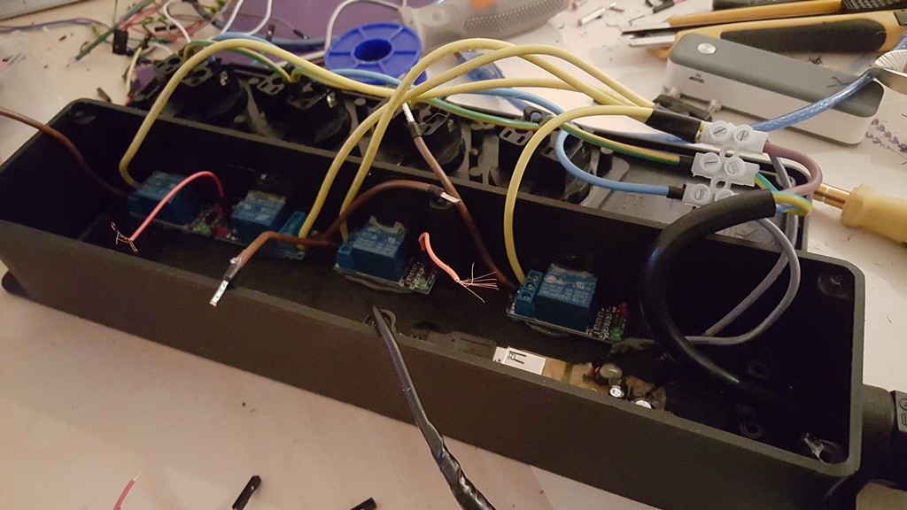
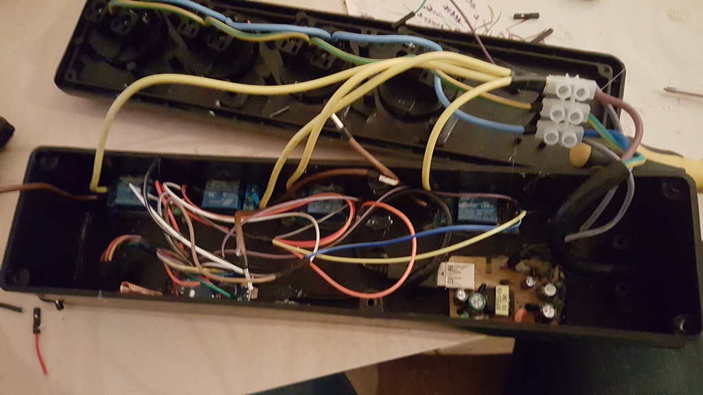
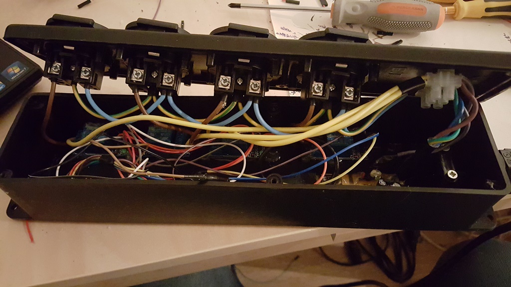
I have decided to make power strip where i can control each socket independently.
Parts needed:
1x Power strip from local shop €18
1x usb charger 500mah from aliexpress €1,30
1x arduino nano aliexpress €2,80
4x relays aliexpress €4
1x radio aliexpress €0,70
And some cables €2 +-
Sketch:
// Example sketch showing how to control physical relays.
// This example will remember relay state even after power failure.

#include <MySensor.h>
#include <SPI.h>

#define RELAY_1  3  // Arduino Digital I/O pin number for first relay (second on pin+1 etc)
#define NUMBER_OF_RELAYS 4 // Total number of attached relays
#define RELAY_ON 1  // GPIO value to write to turn on attached relay
#define RELAY_OFF 0 // GPIO value to write to turn off attached relay

MySensor gw;

void setup()
{
  // Initialize library and add callback for incoming messages
  gw.begin(incomingMessage, AUTO, true);
  // Send the sketch version information to the gateway and Controller
  gw.sendSketchInfo("Stekkerdoos", "1.0");

  // Fetch relay status
  for (int sensor=1, pin=RELAY_1; sensor<=NUMBER_OF_RELAYS;sensor++, pin++) {
    // Register all sensors to gw (they will be created as child devices)
    gw.present(sensor, S_LIGHT);
    // Then set relay pins in output mode
    pinMode(pin, OUTPUT);
    // Set relay to last known state (using eeprom storage)
    digitalWrite(pin, gw.loadState(sensor)?RELAY_ON:RELAY_OFF);
  }
}


void loop()
{
  // Alway process incoming messages whenever possible
  gw.process();
}

void incomingMessage(const MyMessage &message) {
  // We only expect one type of message from controller. But we better check anyway.
  if (message.type==V_LIGHT) {
     // Change relay state
     digitalWrite(message.sensor-1+RELAY_1, message.getBool()?RELAY_ON:RELAY_OFF);
     // Store state in eeprom
     gw.saveState(message.sensor, message.getBool());
     // Write some debug info
     Serial.print("Incoming change for sensor:");
     Serial.print(message.sensor);
     Serial.print(", New status: ");
     Serial.println(message.getBool());
   }
}
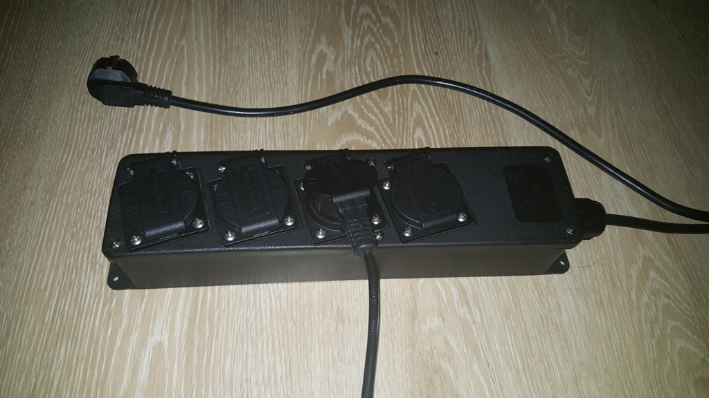
Next step is add led to each socket so that i know which one is on and maybe add buttons for manually control