Changed the arduino.. not the radio .. from UNO to Nano (not the sensor but the gateway).. now it works...
Q
Quinie
@Quinie
Posts
-
Can't get sensors talking -
Can't get sensors talkingHi All
I am working on the version 2 for the first time after being away for awhile.
The gateway is up and running.8-10-2016 02:45:07 RX 0;255;3;0;9;TSP:SANCHK:OKBut my sensors is giving problems.
TSM:INIT
TSM:RADIO:OK
TSP:ASSIGNID:OK (ID=188)
TSM:FPAR
TSP:MSG:SEND 188-188-255-255 s=255,c=3,t=7,pt=0,l=0,sg=0,ft=0,st=bc:
TSM:FPAR
TSP:MSG:SEND 188-188-255-255 s=255,c=3,t=7,pt=0,l=0,sg=0,ft=0,st=bc:
TSM:FPAR
TSP:MSG:SEND 188-188-255-255 s=255,c=3,t=7,pt=0,l=0,sg=0,ft=0,st=bc:
TSM:FPAR
TSP:MSG:SEND 188-188-255-255 s=255,c=3,t=7,pt=0,l=0,sg=0,ft=0,st=bc:
!TSM:FPAR:FAIL
!TSM:FAILURE
TSM:PDT
I have a 4,7 capacitor in place. Any ideas?
-
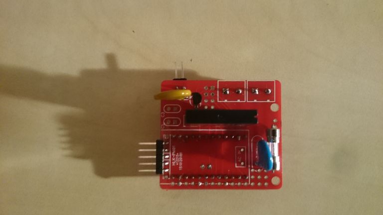
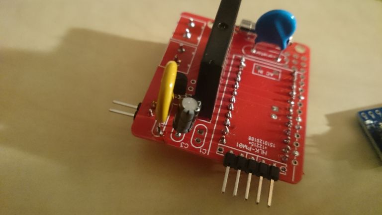
110v-230v AC to Mysensors PCB boardI still have trouble figuring out the C1 and C2. Here are some picture of my build so far.
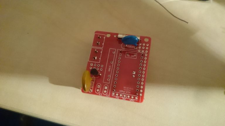
Not sure all the components are placed correctly.C1 is placed with a small 100nf (104) but BOM in zip say's this is wrong.
As you can see i placed this one, cause the 100uf will not fit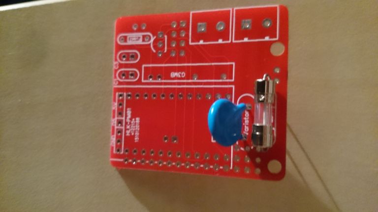
-
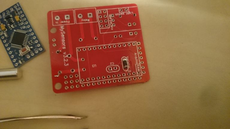
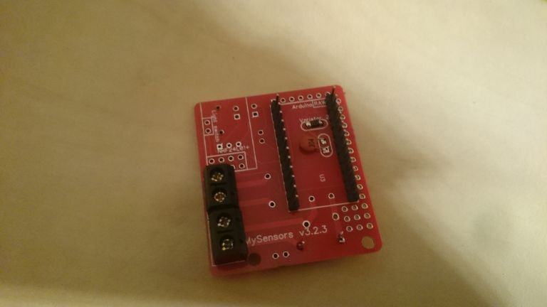
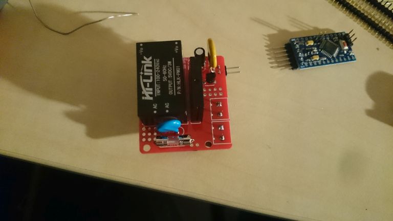
110v-230v AC to Mysensors PCB boardI'm trying to build this nice litte board. Got a long way but now i'm stuck.
The BOM for version 3.2.3
100nF + 100pF Capacitors
4.7uF CapacitorsSchematics.
c1 100nF
c2 100uF
c3 4.7ufI'm don't have a lot of knowlegde but the 100uF seems te be missing from the BOM. The placement of this part is under the HLK. I have a lot of trouble place the C1 and C2.
I have a ceramic one with number 104 in C2. I thought this is the 100nF. So should it be in C1? But it's so small and nice. And then C2 is missing from the BOM and the only 100uF I have from an other project is big. It realy won't fit under the HLK.
Can some-one give some insight on the BOM, C1 and C2, Ceramic code numbers.
This would realy help me and maybe a few others.Also on my board the holes for the fuse 2 where to small had to drill them out. Second the request for a thermal-fuse. But thanks for this great design.