Hello all.
POST UPDATED 13.2.2015
UPDATE 2: Noticed there's a competition going on and as I think this project qualifies, I'm entering it. So there.
I've been following this site for a while now and finally decided to register and share my little project.
I've had a Vera for ages which I've been using for my zwave lights. I really wanted to be able to control my curtains and blinds with it as well, but since it's next to impossible to get moderately priced motors for home automation here in Finland, I started exploring DIY solutions.
I actually thought I had an original idea about using an Arduino and a servo to tilt my blinds but it turned out I'm late to the party.
Anyways, here's my project so far and why it isn't finished: (edit: It is now...)
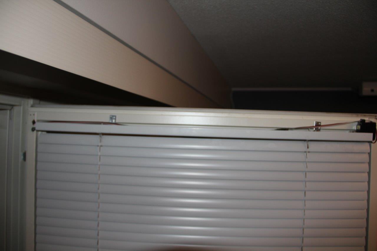
First of all, blinds in Finland are almost always what the Americans call mini-blinds because we put them between the outer and inner windows and they are almost identical everywhere. This means my solution should work for most Finns... ;)
THE MECHANICAL PART:
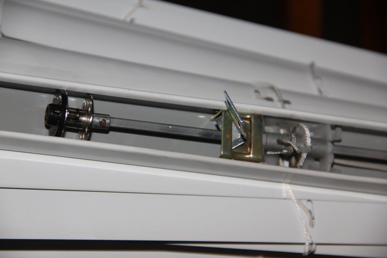
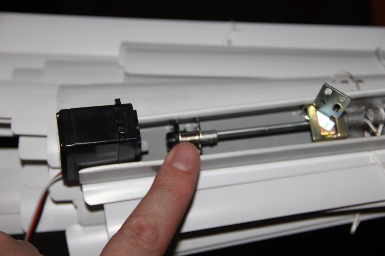
The blinds are adjusted with a rod directly linked to the shaft that tilts the slats.
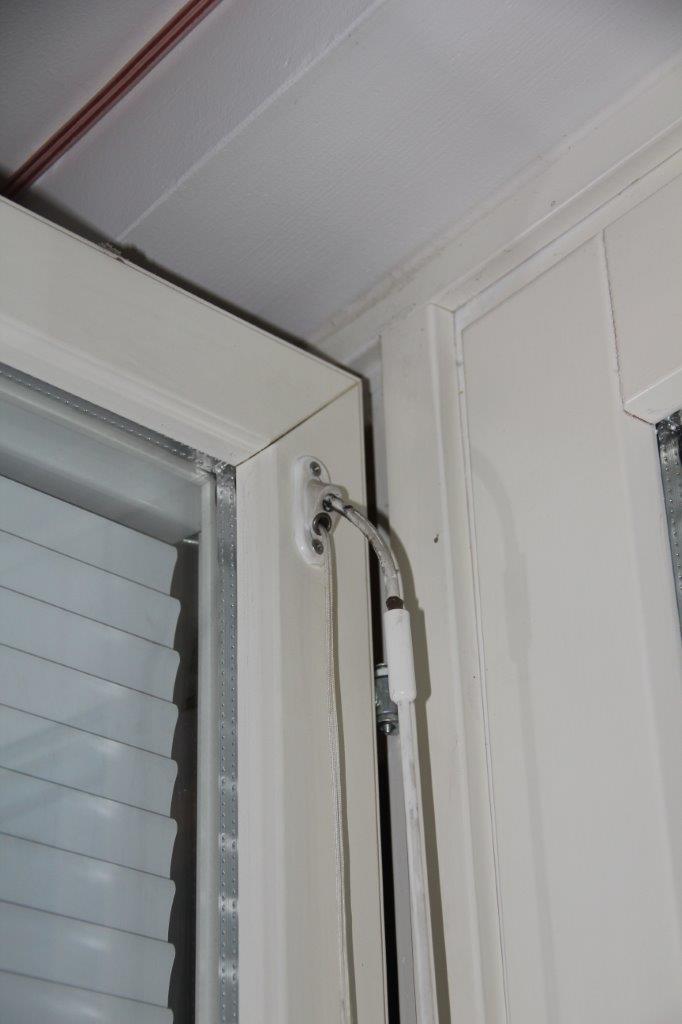
This is removed. (Nevermind the dirt.)
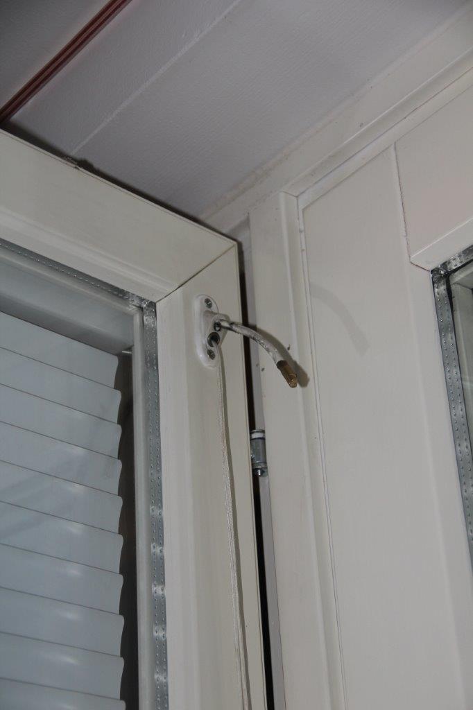
The little connecting springrod needs to removed as well.
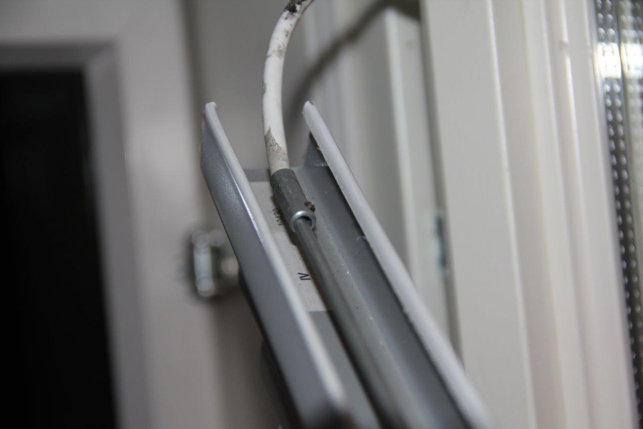
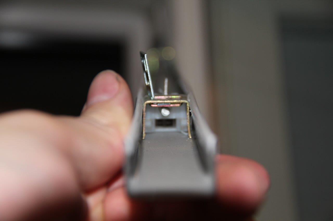
The D-shaft in the middle is the thing the servo needs to move.
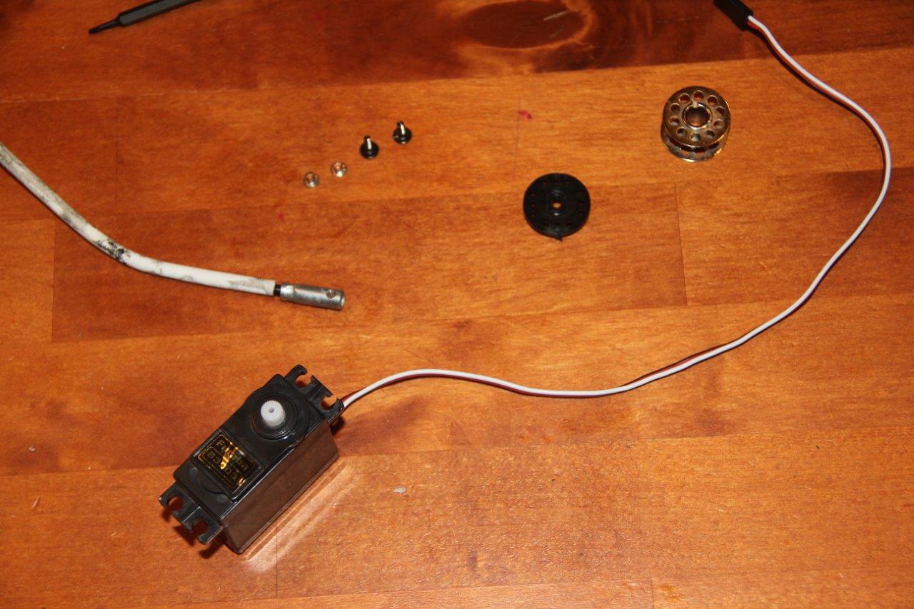
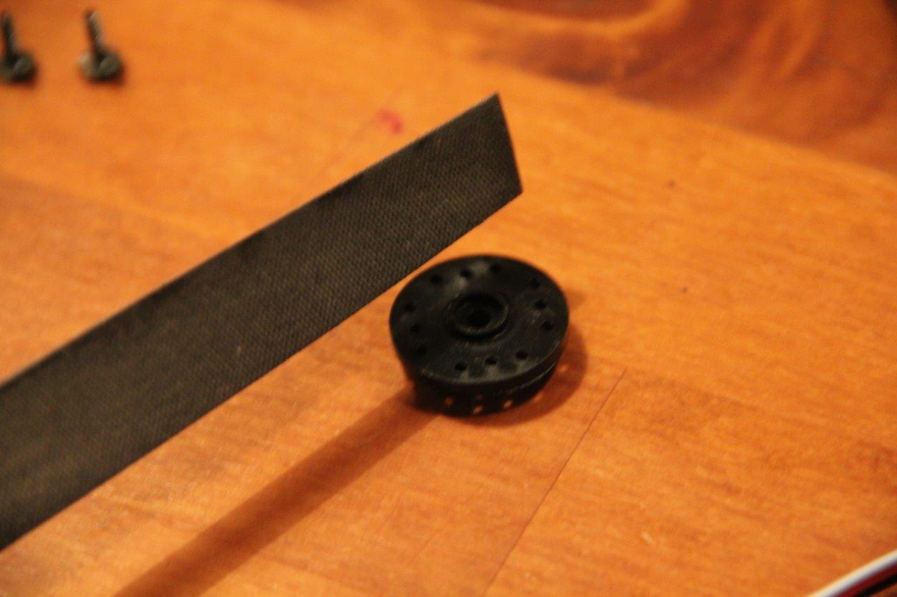
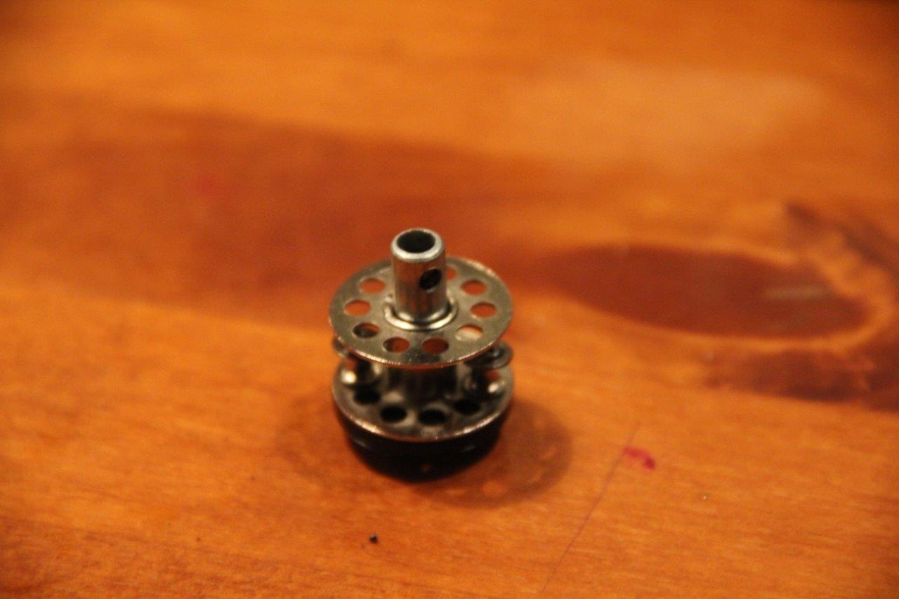
So we need some way to connect the servo spline to the shaft. There are shaft couplers available for servos but they cost about three times as much as the servos! So I swiped an idea from the guys making sail winch servos. Bobbins!
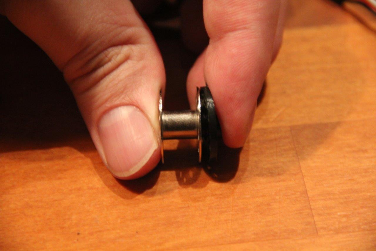
Needs a little persuasion.
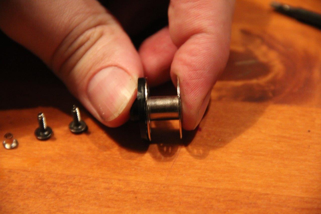
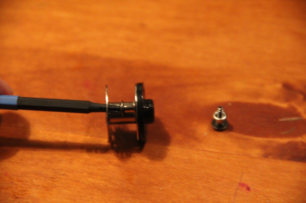
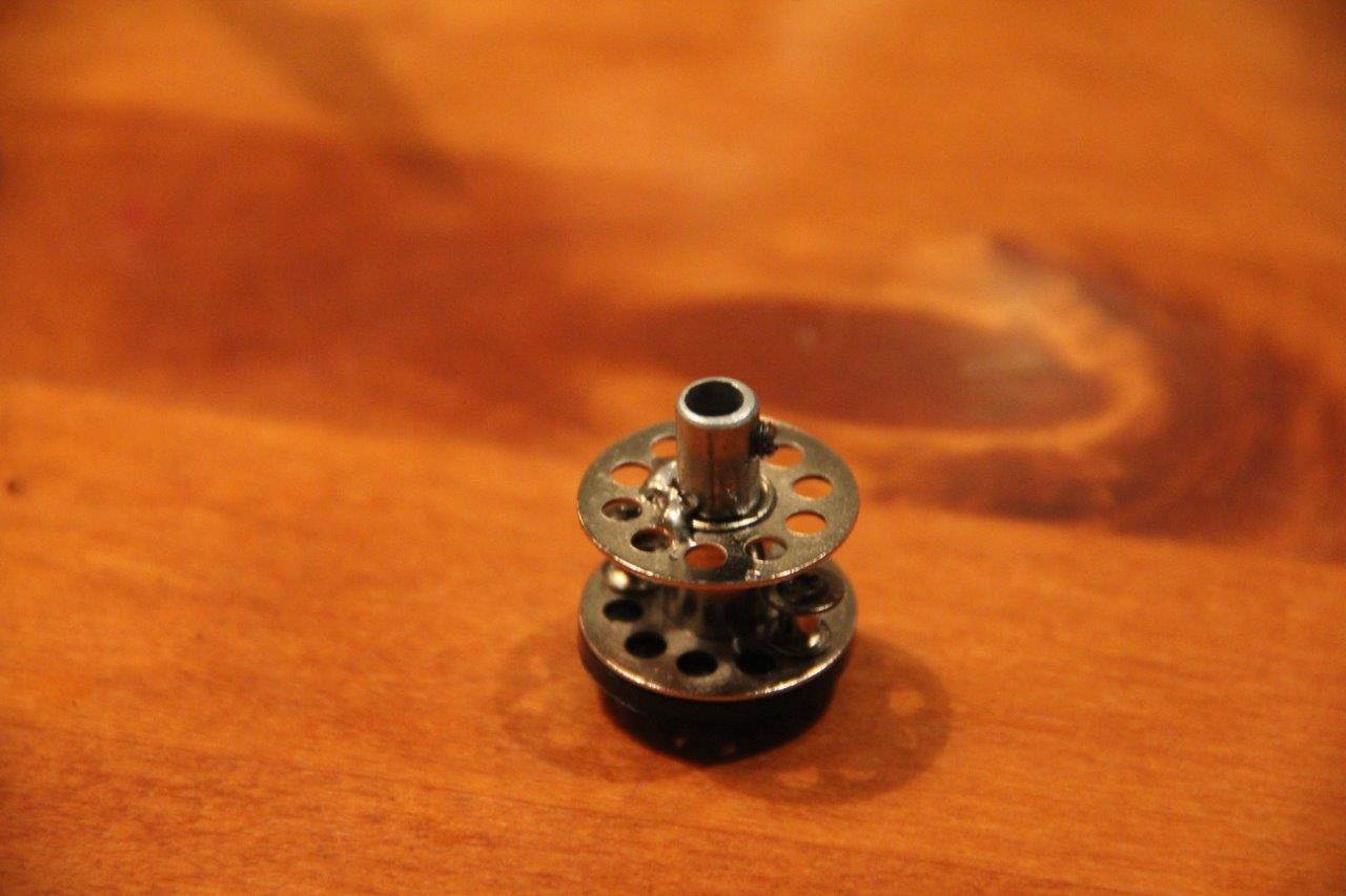
Cut the coupler with the little set screw from the little springrod.
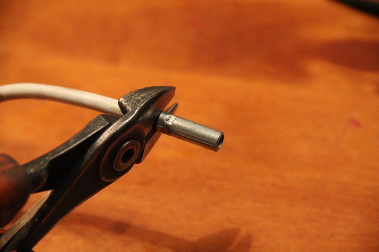
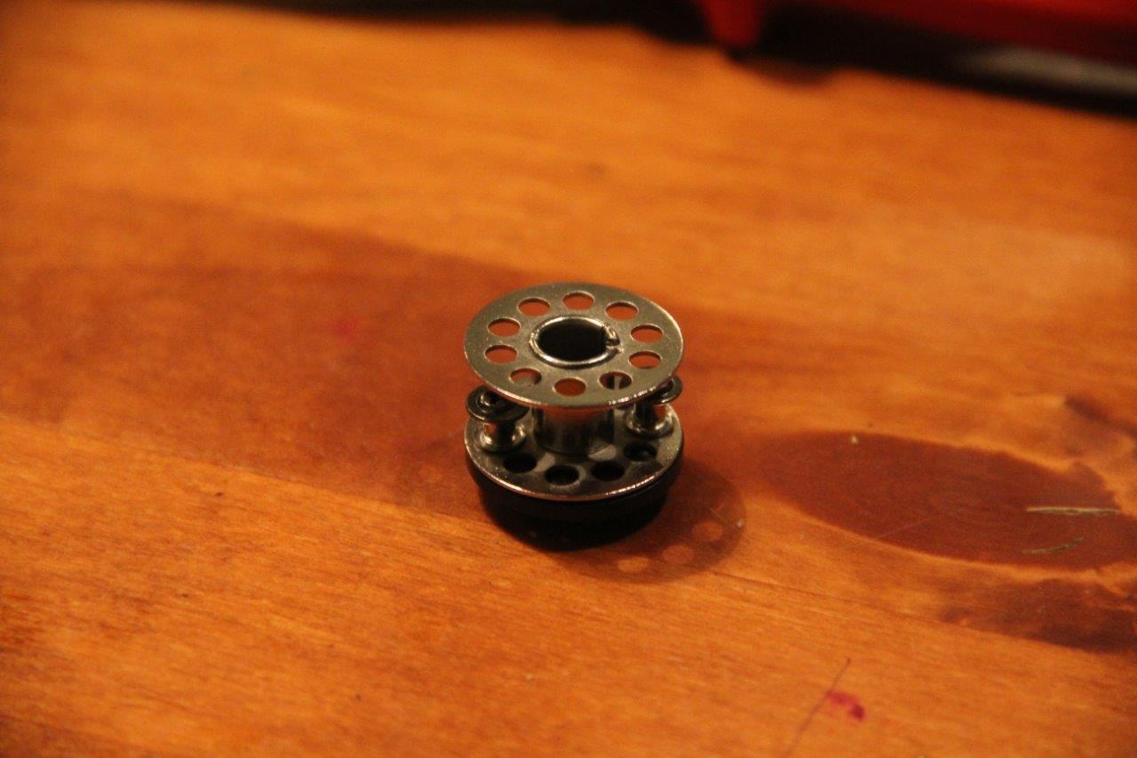
I was going to glue this together but I couldn't find any, so I soldered it. Don't know how well that is going to hold.
I installed the coupler to the opposite side so that the servo won't interfere with the strings used to pull up the blinds. The D-shaft slides with little force.
I adjusted the slats to where I think they are closed (slat outer edge down). Some people have different views about the matter but they're just wrong :) I didn't attach the servo just yet.
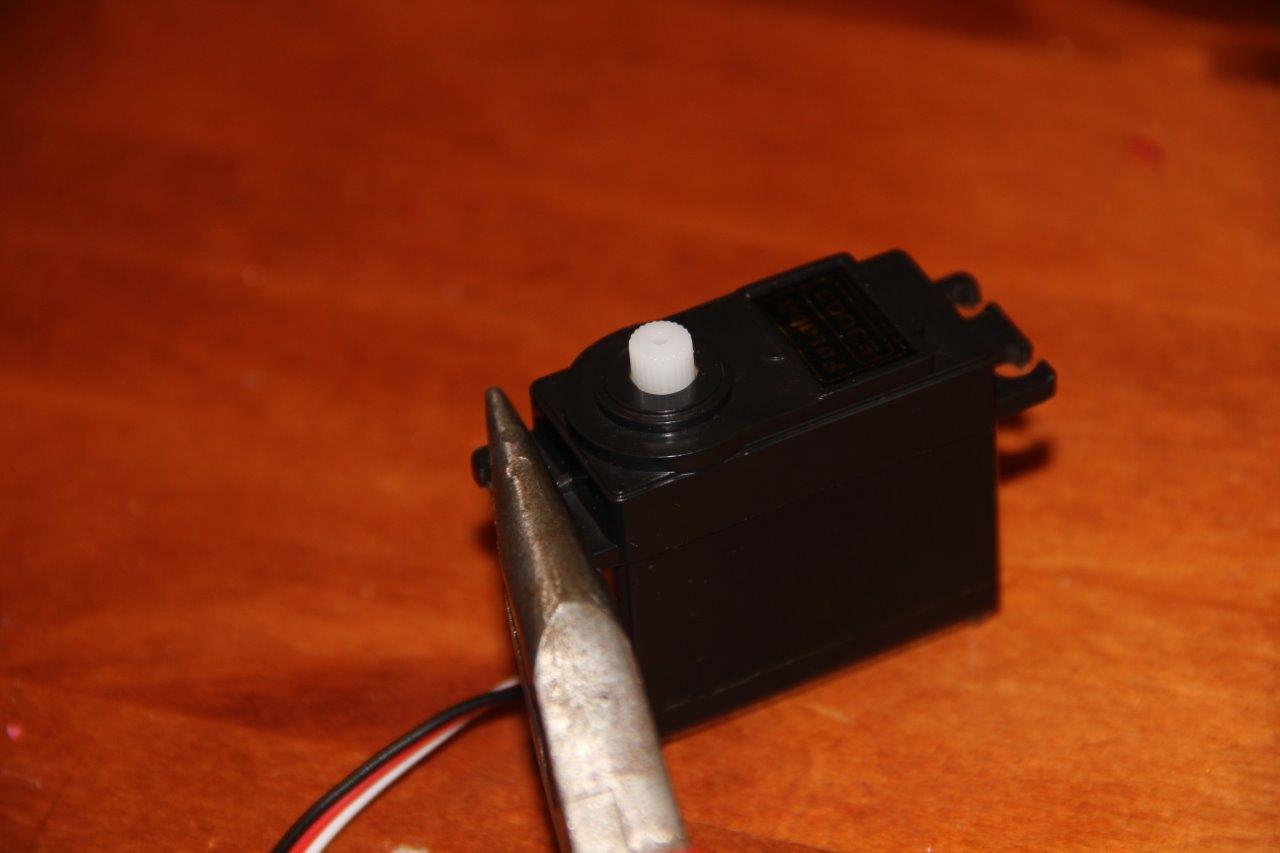
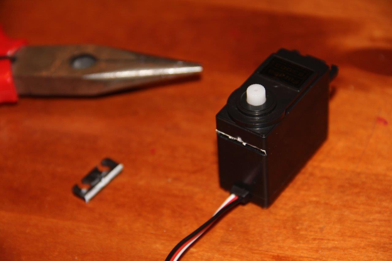
The servo lined up perfectly in the housing and with the D-shaft after I de-tabbed it.
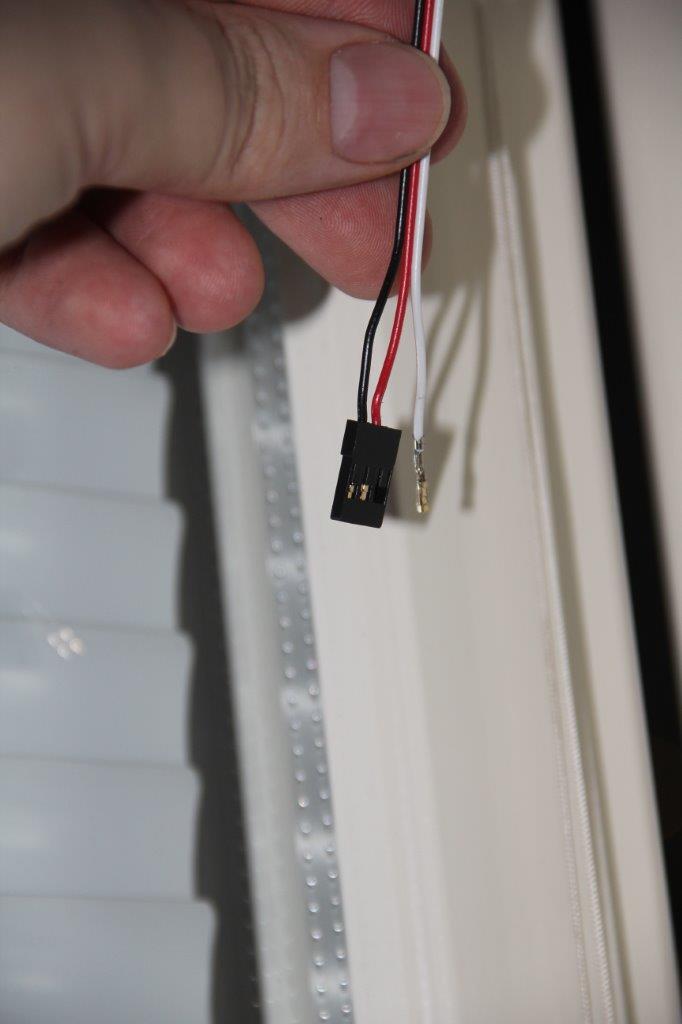
After this, I gently disconnected the wires from the servo extension cable connector so I could thread it back through the rod hole. (The string goes through the lower hole in a spring tunnel)
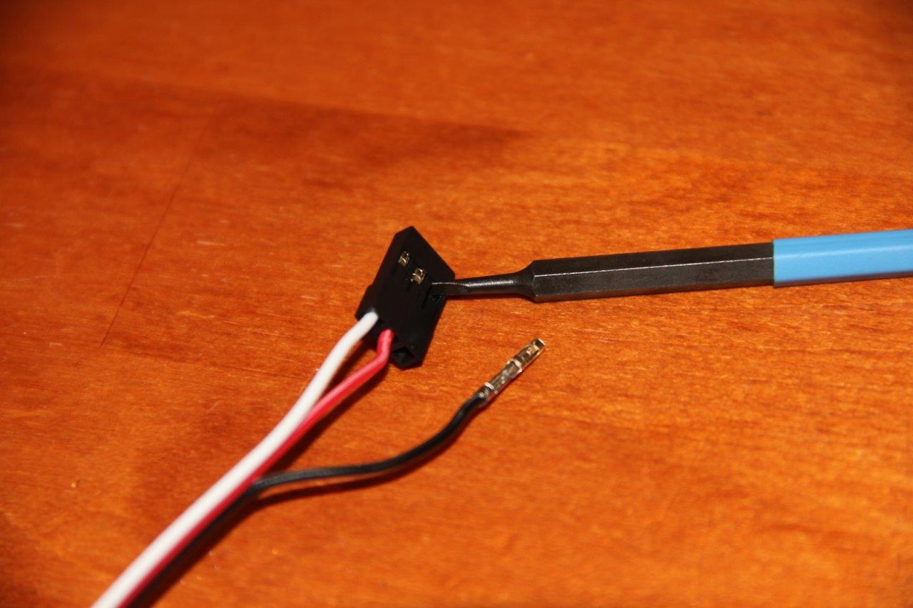
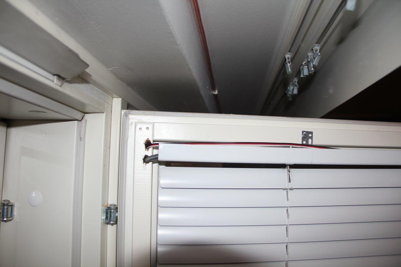
I put the connector back on the other side.
ELECTRICAL PART
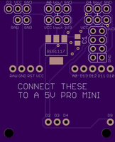
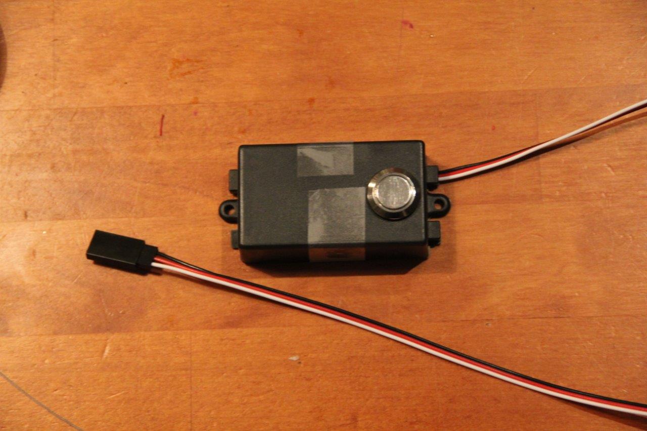
I really wanted to have a physical button to adjust the blinds so I put one in this temporary box along with a 5v pro mini.
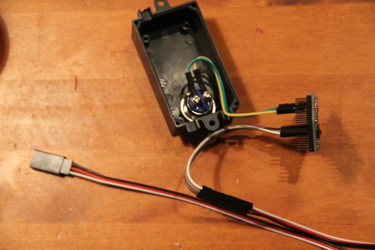
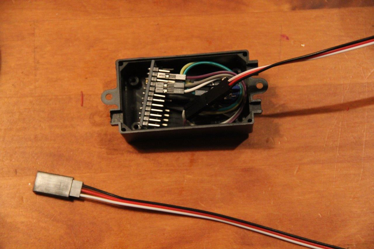
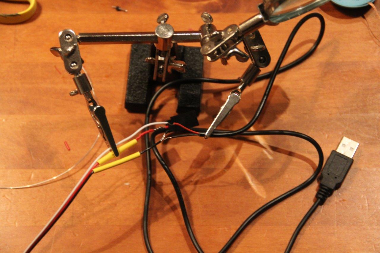
I spliced in to another servo extension cable 5v from a phone charger. (Note to self: don't cut the wires so damn close to the connector!)
This makes it easy to connect the button box with the servo cable and both are powered.
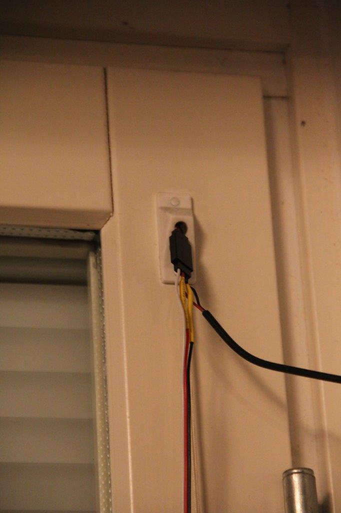
The final version will have a DC socket at the junction so I can just run an easily disconnectable plug to every window. The holes are always on the hinge side so the window can be opened even without unplugging. I'll also wrap everything nicely in white heat shrink tubing and the box will be nicer, too.
THE CODE PART
This one was/is the most difficult for me because I had exactly zero experience with C++. Or any C. I've used a bit of python and some simple shell scripts but this was new. Anyways, I managed to write this:
**UPDATE:**This is just test code for use without the Mysensors stuff. Scroll down for working code.
Why this is bit complicated is because I wanted the button to do two things:
-
Press once; toggle open/close
-
Keep pressing the button; sweep back and forth until button is released and stop there.
At the moment it does just that.
I connected the servo to the shaft once I figured out with the button which way was closed and which way was open. 180 degrees was exactly the difference between open and closed.
Now some of you may be thinking, "what the hell has this got to do with mysensors?" That's why the title is tagged [WIP]. I've been waiting for my NRF24L01+ -modules to arrive for a month and finally today they arrived.
And they're not NRF24L01+ -modules.
BUY YOUR RADIOS FROM THE MYSENSORS EBAY STORE LINK
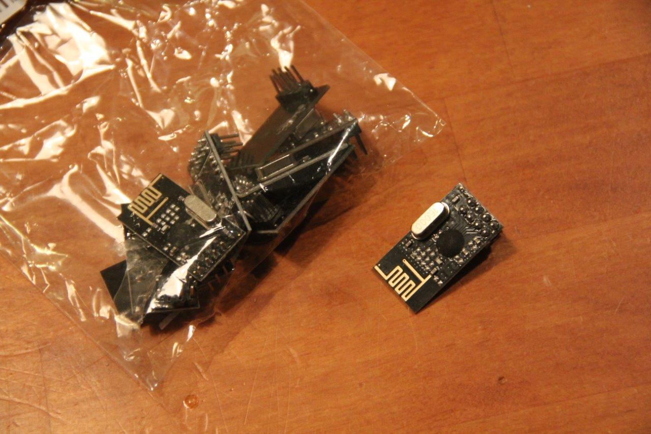
They were sold as NRF24L01+'s but they definitely are not. So now I have to wait again.
Meanwhile, could someone tell me if they see something horribly wrong with this sketch I've been planning to use once I do get the radios? I can't really test it. (This works well now)
UPDATE: Code is VERY much refactored and improved (works well)
link text
Oh yeah, some video:
Sorry for the long post.