OK that's embarrassing. It seems I connected interrupt / DIO0 to gnd. But i've reconnected the entire thing several times, including swapping... Anyway thanks for pointing it out. I still get some NACKs and the mqqt is not working anymore for some reason, but I'll figure that out, and do another post if necessary. Thanks for pointing it out!
T
tomvanderputte
@tomvanderputte
Posts
-
FindParents on RFM69HW node -
FindParents on RFM69HW nodeMy set-up is as follows:
Gateway:
RPi 3B+ (64 bit debian)
MySGW dev branch, master would not build because of know issue (not sure which one anymore)
Compiled MySGW with:--my-transport='rfm69' --my-rfm69-frequency='433' --my-is-rfm69hwNode:
Then I have 1 test node on an Arduino Pro mini 3.3V, with the same radio. Sketch has the following defined:#define MY_DEBUG #define MY_RADIO_RFM69 #define MY_RFM69_FREQUENCY RFM69_433MHZ #define MY_IS_RFM69HW #define MY_RFM69_NEW_DRIVER //Becasue RPi 3B+ as Gateway #define MY_NODE_ID 2Problem:
The node only gets FPAR: No Reply all the time.
Log for the node :MCO:BGN:INIT NODE,CP=RPNNA---,FQ=16,REL=255,VER=2.3.2 TSM:INIT TSF:WUR:MS=0 TSM:INIT:TSP OK TSM:INIT:STATID=2 TSF:SID:OK,ID=2 TSM:FPAR ?TSF:MSG:SEND,2-2-255-255,s=255,c=3,t=7,pt=0,l=0,sg=0,ft=0,st=OK: !TSM:FPAR:NO REPLY TSM:FPAR ?TSF:MSG:SEND,2-2-255-255,s=255,c=3,t=7,pt=0,l=0,sg=0,ft=0,st=OK: !TSM:FPAR:NO REPLY TSM:FPAR TSF:MSG:SEND,2-2-255-255,s=255,c=3,t=7,pt=0,l=0,sg=0,ft=0,st=OK: !TSM:FPAR:NO REPLY TSM:FPAR ?TSF:MSG:SEND,2-2-255-255,s=255,c=3,t=7,pt=0,l=0,sg=0,ft=0,st=OK: !TSM:FPAR:FAILAlthough the gateway sees the message coming across:
INFO  Starting gateway...
INFO  Protocol version - 2.4.0-alpha
DEBUG MCO:BGN:INIT GW,CP=RPNGL---,FQ=NA,REL=1,VER=2.4.0-alpha
DEBUG TSF:LRT:OK
DEBUG TSM:INIT
DEBUG TSF:WUR:MS=0
DEBUG TSM:INIT:TSP OK
DEBUG TSM:INIT:GW MODE
DEBUG TSM:READY:ID=0,PAR=0,DIS=0
DEBUG MCO:REG:NOT NEEDED
DEBUG MCO:BGN:STP
DEBUG MCO:BGN:INIT OK,TSP=1
DEBUG GWT:RMQ:CONNECTING...
DEBUG connected to 192.168.1.24
DEBUG GWT:RMQ:OK
DEBUG GWT:TPS:TOPIC=mysensors-out/0/255/0/0/18,MSG SENT
DEBUG TSM:READY:NWD REQ
DEBUG ?TSF:MSG:SEND,0-0-255-255,s=255,c=3,t=20,pt=0,l=0,sg=0,ft=0,st=OK:
DEBUG TSF:MSG:READ,2-2-255,s=255,c=3,t=7,pt=0,l=0,sg=0:
DEBUG TSF:MSG:BC
DEBUG TSF:MSG:FPAR REQ,ID=2
DEBUG TSF:CKU:OK,FCTRL
DEBUG TSF:MSG:GWL OK
DEBUG !TSF:MSG:SEND,0-0-2-2,s=255,c=3,t=8,pt=1,l=1,sg=0,ft=0,st=NACK:0
DEBUG TSF:MSG:READ,2-2-255,s=255,c=3,t=7,pt=0,l=0,sg=0:
DEBUG TSF:MSG:BC
DEBUG TSF:MSG:FPAR REQ,ID=2
DEBUG TSF:CKU:OK,FCTRL
DEBUG TSF:MSG:GWL OK
DEBUG !TSF:MSG:SEND,0-0-2-2,s=255,c=3,t=8,pt=1,l=1,sg=0,ft=0,st=NACK:0
DEBUG TSF:MSG:READ,2-2-255,s=255,c=3,t=7,pt=0,l=0,sg=0:
Tried so far
- Disabling the HW flag (was pretty sure it is an HW, but seen examples of others that were mistaken). Leads to not initialising.
- A different radio (I tried switching them, outcome is similar)
- Different distances (1m, 4m, 10m with wooden floors between them)
I followed the debugging flow, and came to the point were it says to add a capacitator to the radio. But everywhere i see a reference to that, it has to do with the nrf24 radios. Does the same go for the RFM69(HW) radio's? So is this the next step or should try something else (I currently have no capacitors at the ready).
-
TV on/off monitor using TV USB port@parachutesj is from a design perspective that you don't like it? Or because it can actually damage the node?
I like the expire binding, thanks for the tip. The ldr is usable, but for estethic reasons I'll see if I can find a different solution, thanks.
-
TV on/off monitor using TV USB portThanks everyone for the suggestions, I'll consider my options!
-
TV on/off monitor using TV USB port@mfalkvidd awesome thanks! So would it make sense to take this active approach? Or a more passive approach with external power, and to map the +5v fro the usb port to one of the gpio to sense the on/off status? That way it could send the actual status to the gateway.
-
TV on/off monitor using TV USB portI'm trying to figure out what the best way is to create a sensor that determines if the TV is in stand-by mode, or is ON. I'm planning on using:
arduino pro mini 3.3V
RFM69HW radio at 433MHz (probably disabling the H mode, test show I don't need it over the required distance)
An pretty old Samsung (dumb) TV (LE32B530)There's a few options that I'm looking at, but in my mind the ideal situation would be to use the USB service port (which is used for firmware updates only), to power the arduino, which has a very simple sketch to ping ever X seconds to the gateway. Once the TV is set to stand-by it automatically stops pinging, and using a timer in Openhab, I can determine if has been switched off. This way I don't have to use an external power source.
Now this is based on a few assumptions:
- the USB port will deliver enough power for the Arduino (using a step down converter)
- the USB port does not remain powered during stand-by
- the Openhab timer method is not to stressful in terms of performance
I can test 2 relatively easily I think with a old USB cable, with the ends stripped of to test the voltage between GND an +5V.
I'm struggling with 1 however. I don't know how to test if the USB port delivers enough amps for the arduino to function and to power the radio. Can I test or find out about the max. current the USB port can safely supply?
I have seen that an idling usb stick takes up about 34 mA, and that writing to a usb stick can take up to about 100mA. But I'm not sure the port is even set to be able to write, so that doesn't make me much wiser. I've been able to find the service manual for the TV, and there's this schematic:
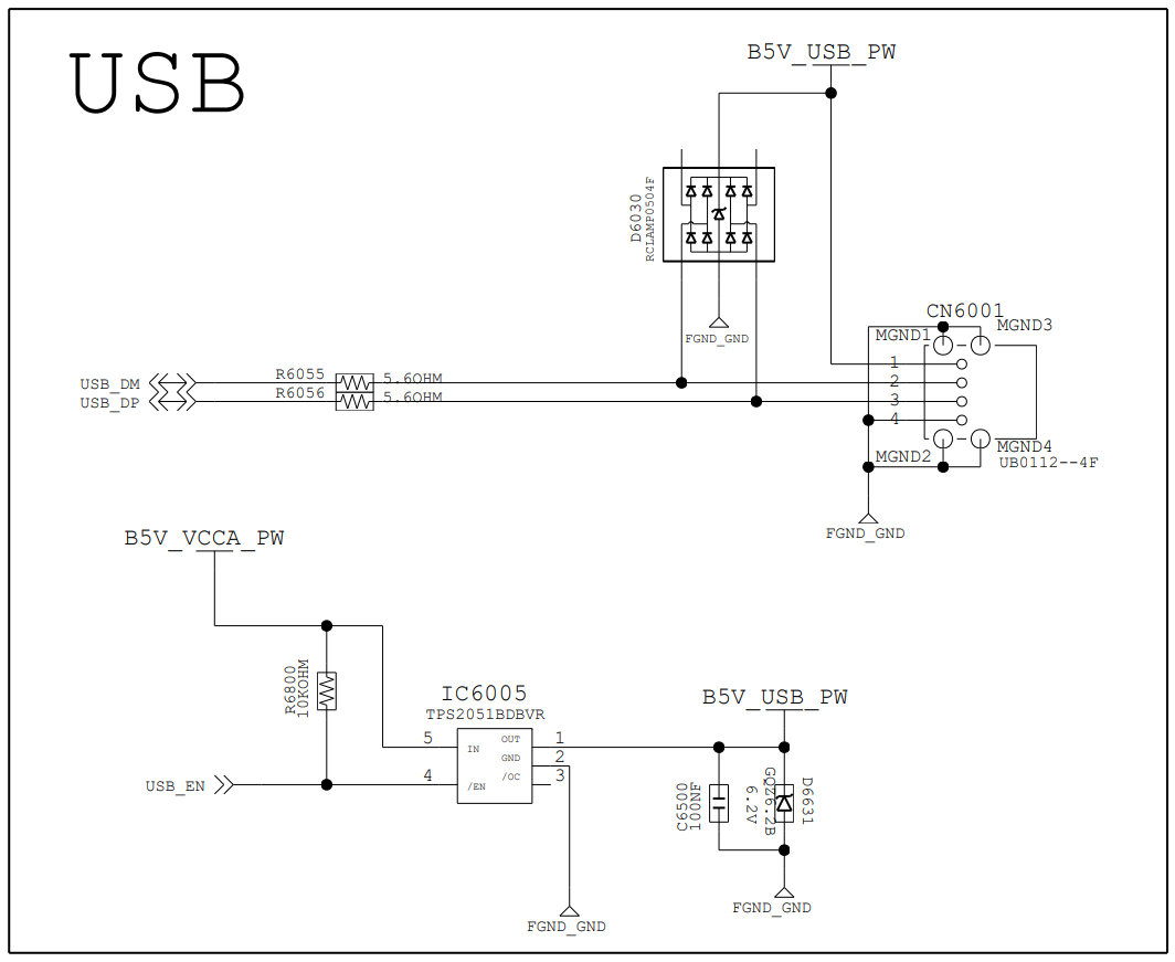 It doesn't make any sense to me, but maybe someone can deduce anything from it?