2AAA battery NRF24 Sensor PCB with ATmega 328p
-
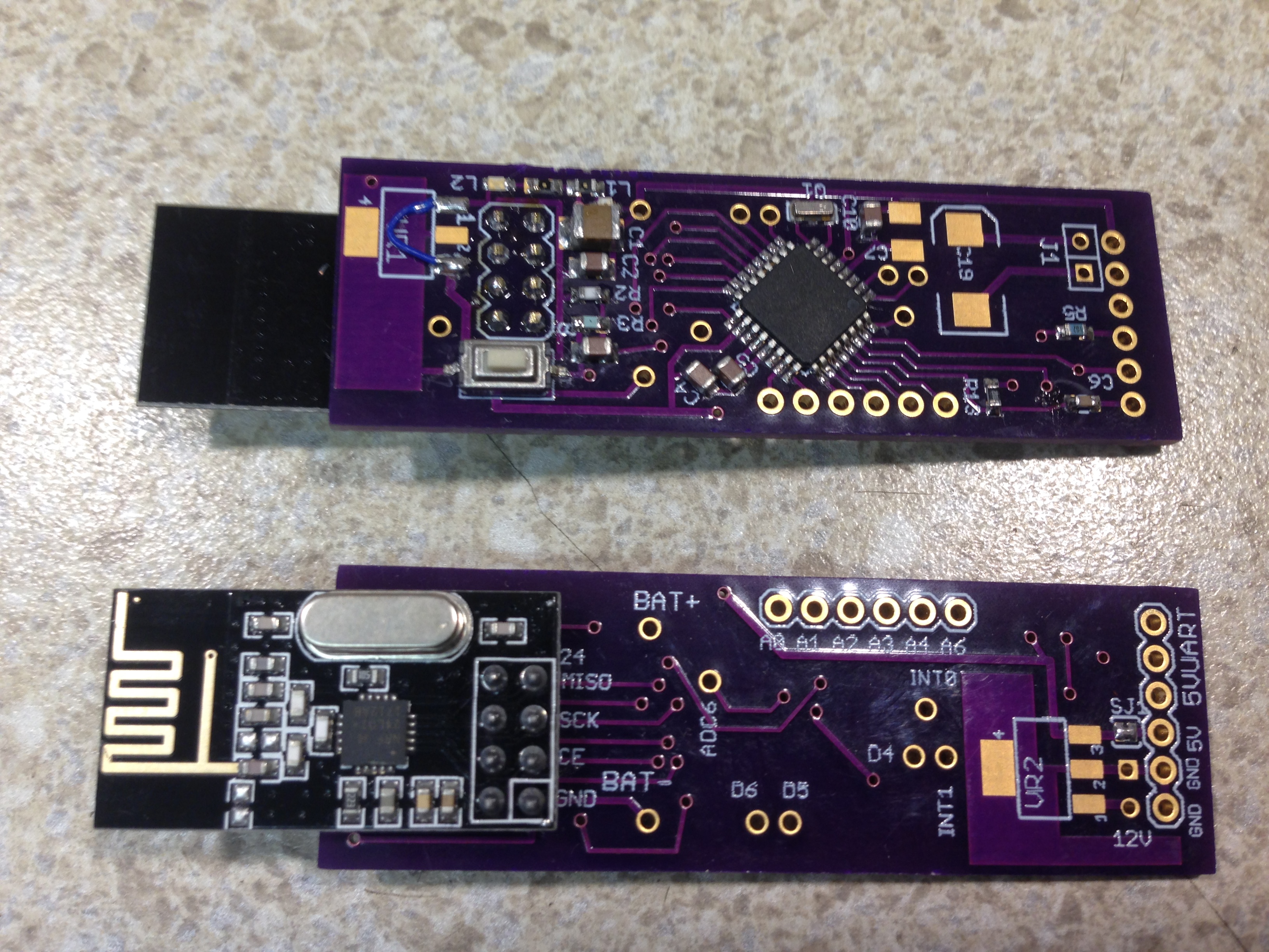
Here is a MySensor node implementation on a PCB that can be ordered at OSHPARK.com. It contains a "Arduino pro - mini" chip( ATmega 328p) and has the footprint for a nrf24 radio built in as well as footprints for the necessary voltage regulators and capacitors if the node is to be run from 5V or 7-12V supplies. The Bat+/Bat- solder positions take either a 2 AAA or a 2 AA battery case. When used as a battery operated node, for example as a door/window sensor the batteries last about 2 years. The node has a built in way of measuring the battery voltage that doesn't itself deplete the battery slowly and features two LEDs driven from one digital pin.
The PCB's can be ordered at OSHPARK.com in the US , search in the shared project for "nrfMysensor. They cost around $9 per 3. Soldering is not too terribly hard. The smallest components are the two LEDs which can be left out. The arduino chip can be "harvested" from a pro/mini board, either the 8mhz/3.3V version for battery operation or the 16mhz/5V version for 5V-12V operation. Or load the appropriate bootloader onto a blank chip.
The EagleCAD board and schematic files can be found here :https://github.com/garyStofer/Eagle5_PCB/tree/master/nRF_Mysensor. The schematic contains notes on various build options.
Some example of using the boards in a battery scenario can be found here https://github.com/garyStofer/MyMySensors2.1 Wire_Trip_alarm and PIR_alarm_PCint
-
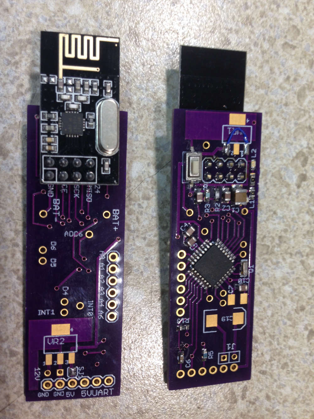
Here is a MySensor node implementation on a PCB that can be ordered at OSHPARK.com. It contains a "Arduino pro - mini" chip( ATmega 328p) and has the footprint for a nrf24 radio built in as well as footprints for the necessary voltage regulators and capacitors if the node is to be run from 5V or 7-12V supplies. The Bat+/Bat- solder positions take either a 2 AAA or a 2 AA battery case. When used as a battery operated node, for example as a door/window sensor the batteries last about 2 years. The node has a built in way of measuring the battery voltage that doesn't itself deplete the battery slowly and features two LEDs driven from one digital pin.
The PCB's can be ordered at OSHPARK.com in the US , search in the shared project for "nrfMysensor. They cost around $9 per 3. Soldering is not too terribly hard. The smallest components are the two LEDs which can be left out. The arduino chip can be "harvested" from a pro/mini board, either the 8mhz/3.3V version for battery operation or the 16mhz/5V version for 5V-12V operation. Or load the appropriate bootloader onto a blank chip.
The EagleCAD board and schematic files can be found here :https://github.com/garyStofer/Eagle5_PCB/tree/master/nRF_Mysensor. The schematic contains notes on various build options.
Some example of using the boards in a battery scenario can be found here https://github.com/garyStofer/MyMySensors2.1 Wire_Trip_alarm and PIR_alarm_PCint
@garystofer what's your built in way to read the battery that you mentioned?
-
On this board I use a resistor voltage divider with the low end connected to a digital pin instead of ground. When a voltage reading is to be obtained the digital pin is commanded to become an output and set low, then wait for the filter capacitor to charge, take the reading and set the pin back to input. The same digital pin also has the push button switch connected which is checked elsewhere in the code, in that case the two resistors making up the voltage divider become the pull-up resistor for the switch . So the resistors and digital pin serve double duty. The internal reference of the 328p ( 1.1V ) is used as the reference for the ADC , which results in a very precise result.

-
Hmmm ... is that accurate? I thought digital LO may be higher than actual GND.
-
Another way to do it is with multi-megaohm resistors for the voltage divider and use a 1uf capacitor in parallel with the resistor that's attached to ground. That way there's still enough charge for the ADC to read, but the current drain is negligible.
-
Or ditch the Ldo completely and run from a 3v battery supply. That's how most people do it. Then you don't need a voltage divider to read the battery voltage, so there's no wasted current at all.
-
Or ditch the Ldo completely and run from a 3v battery supply. That's how most people do it. Then you don't need a voltage divider to read the battery voltage, so there's no wasted current at all.
@neverdie
The LDO is only used when running from 5 or 12V supplies. Cant measure 3.3V with a 1.1V reference . -
@neverdie said in 2AAA battery NRF24 Sensor PCB with ATmega 328p:
Hmmm ... is that accurate? I thought digital LO may be higher than actual GND.
Yes, perfectly accurate. The output stage is a FET switch and the current it switches to GND is ~2 micro amps, It's 0V. One could measure the VCC an other way not needing a voltage divider by configuring the ADC so that it uses the VCC as the reference and then measure the internal 1.1V reference. However that takes re-configuring the ADC each time into and out of this mode if you need the ADC for other measurements as well and doesn't save any pins.
-
@neverdie said in 2AAA battery NRF24 Sensor PCB with ATmega 328p:
Hmmm ... is that accurate? I thought digital LO may be higher than actual GND.
Yes, perfectly accurate. The output stage is a FET switch and the current it switches to GND is ~2 micro amps, It's 0V. One could measure the VCC an other way not needing a voltage divider by configuring the ADC so that it uses the VCC as the reference and then measure the internal 1.1V reference. However that takes re-configuring the ADC each time into and out of this mode if you need the ADC for other measurements as well and doesn't save any pins.
@garystofer said in 2AAA battery NRF24 Sensor PCB with ATmega 328p:
One could measure the VCC an other way not needing a voltage divider by configuring the ADC so that it uses the VCC as the reference and then measure the internal 1.1V reference.
Yes this is how I do it, except even more extreme: I measure the battery voltage during the entire tx interval, and pick the lowest voltage (which, it turns out, is always the last measurement).
So, I suspect the extreme method can be made more efficient by measuring just after Tx completes.
Hello! It looks like you're interested in this conversation, but you don't have an account yet.
Getting fed up of having to scroll through the same posts each visit? When you register for an account, you'll always come back to exactly where you were before, and choose to be notified of new replies (either via email, or push notification). You'll also be able to save bookmarks and upvote posts to show your appreciation to other community members.
With your input, this post could be even better 💗
Register Login