💬 The Harvester: ultimate power supply for the Raybeacon DK
-
@Mishka Have you been able to test the spv1050 yet, and if so, how did it go?
One of the things I like about the spv1050 is that on paper it has a buck-boost configuration with a very wide input range of 0.15v to 18v. It seems that most chips that can work with as little as 0.15v as input are boost only, which makes them not as versatile as the spv1050.
The cold boot minimum voltage for the buck-boost configuration is 2.6v, however, so you'd want it to default to boost-only mode if it runs out of juice. In boost-only mode, the cold-boot voltage would be 0.5v.
Which leads to a quandary: how does one know in a cold-boot scenario what the input voltage would be? In theory it could be quite high (if, say, you walked into a dark room and flipped on a light switch), but if you set it conservatively for that kind of scenario, you risk missing start-up opportunities where lower voltages are available and would have been enough had boot-only been the default.
@NeverDie From my understanding it's a game of the harvesting source. In boost configuration V_in must be lower than the end of charge V_eoc value which limits possible input to low voltage sources only, such as a TEG or some PV panels.
On the other hand for buck-boost configuration there is the cold-boot voltage indeed. It's also somewhat unclear how it will maintain V_store when V_in later drops below 2.6V.
I've ordered number of KXOB25_02X8F panels to give it a try with one, two, and three "solar bits" in series. The Harvester board is configured to V_oc = 12V so it's also interesting to check how well this will work in a single panel configuration. The panels and boards are somewhere on the way (China Post), hope to build everything in early February.
-
@NeverDie From my understanding it's a game of the harvesting source. In boost configuration V_in must be lower than the end of charge V_eoc value which limits possible input to low voltage sources only, such as a TEG or some PV panels.
On the other hand for buck-boost configuration there is the cold-boot voltage indeed. It's also somewhat unclear how it will maintain V_store when V_in later drops below 2.6V.
I've ordered number of KXOB25_02X8F panels to give it a try with one, two, and three "solar bits" in series. The Harvester board is configured to V_oc = 12V so it's also interesting to check how well this will work in a single panel configuration. The panels and boards are somewhere on the way (China Post), hope to build everything in early February.
@Mishka Please do let us know how your testing goes once you get your parts together.
I've tried "solar bits" of the type you linked. FWIW, I found they perform quite well with sunlight but surprisingly poorly on indoor LED lighting (where, say, one of the keychain scavenged solar cells seems to perform relatively better). Just FYI, depending on what light source you are planning to use. In that regard, perhaps there's a further dependency on the type of indoor LED one has. I have no data on that, as I've only tried what I currently have installed, which are from CREE.
-
@Mishka Please do let us know how your testing goes once you get your parts together.
I've tried "solar bits" of the type you linked. FWIW, I found they perform quite well with sunlight but surprisingly poorly on indoor LED lighting (where, say, one of the keychain scavenged solar cells seems to perform relatively better). Just FYI, depending on what light source you are planning to use. In that regard, perhaps there's a further dependency on the type of indoor LED one has. I have no data on that, as I've only tried what I currently have installed, which are from CREE.
@NeverDie Thanks for the info! I've never used IXYS cells before - chose them mostly for the size. The harvesting IC and the SoC are very low power so I hope there's will be a chance to reach a usable configuration indoors. Anyhow, will share my measurements, of course.
-
@Mishka Please do let us know how your testing goes once you get your parts together.
I've tried "solar bits" of the type you linked. FWIW, I found they perform quite well with sunlight but surprisingly poorly on indoor LED lighting (where, say, one of the keychain scavenged solar cells seems to perform relatively better). Just FYI, depending on what light source you are planning to use. In that regard, perhaps there's a further dependency on the type of indoor LED one has. I have no data on that, as I've only tried what I currently have installed, which are from CREE.
@NeverDie Just received the KXOB25-02X8F panels. In short - you was right, and I was too optimistic about indoor lights.
Generally speaking, the pannel works really not bad and looks extremely handy. However, in order to achieve the desired 2.6V it has to be illuminated with greatly above 1000 lux which roughly equals bright supermarket or factory lights. And yes, it seem differentiates LED lamps from the sun.
Accordingly to my (totally uncalibrated) luxmeter:
- Living room room: 50 lx - 0.4 V
- Overcast daylight, indoors: 250 lx - 1.4 V
- Supermarket lights: 1300 - 2.0V
- Overcast daylight, street: 2000 lx - 2.7V
Therefore, it's safe to say that two of 02X8F would make it acceptably work in buck-boost configuration. By acceptable I mean it could charge an ML2032 battery, but batteryless operation is quite limited indeed.
This pushes me to review use-cases for the Harvester. It has two input sources - first one is spv1050, and another one is MIC5205 3.2V LDO. I'm thinking about switching the spv1050 to boost configuration and cover only PV and TEG sources from 75 mV to 3.6V. At the same time LDO could handle sources capable to deliver 2.0V and above (2.0-3.2V with battery removed, and 3.2V to 16V with or without a battery). The point here is that at higher voltages there is likely a more capable source so MPPT might not be required.
Such, although less flexible, one or two KXOB25-05X3F, 30mW each, and a "supercap" should be enough to power the nRF52 (and even an extra module) without the need of a battery. For more demanding applications, up to five KXOB25-14X1F could be used delivering 150mW in total. With 3.2V, 70mA limit on the spv1050 battery pin it sounds like a good match.
Another option is to make the Harvester configurable via solder jumpers. This will put four more jumpers on top of it (and there are five on the back side already). Well, although possible, sounds too complicated as for one inch board.
Any thoughts?
P.S. I'm going to assembly a buck/boost board anyway so we can compare later.
-
@NeverDie Just received the KXOB25-02X8F panels. In short - you was right, and I was too optimistic about indoor lights.
Generally speaking, the pannel works really not bad and looks extremely handy. However, in order to achieve the desired 2.6V it has to be illuminated with greatly above 1000 lux which roughly equals bright supermarket or factory lights. And yes, it seem differentiates LED lamps from the sun.
Accordingly to my (totally uncalibrated) luxmeter:
- Living room room: 50 lx - 0.4 V
- Overcast daylight, indoors: 250 lx - 1.4 V
- Supermarket lights: 1300 - 2.0V
- Overcast daylight, street: 2000 lx - 2.7V
Therefore, it's safe to say that two of 02X8F would make it acceptably work in buck-boost configuration. By acceptable I mean it could charge an ML2032 battery, but batteryless operation is quite limited indeed.
This pushes me to review use-cases for the Harvester. It has two input sources - first one is spv1050, and another one is MIC5205 3.2V LDO. I'm thinking about switching the spv1050 to boost configuration and cover only PV and TEG sources from 75 mV to 3.6V. At the same time LDO could handle sources capable to deliver 2.0V and above (2.0-3.2V with battery removed, and 3.2V to 16V with or without a battery). The point here is that at higher voltages there is likely a more capable source so MPPT might not be required.
Such, although less flexible, one or two KXOB25-05X3F, 30mW each, and a "supercap" should be enough to power the nRF52 (and even an extra module) without the need of a battery. For more demanding applications, up to five KXOB25-14X1F could be used delivering 150mW in total. With 3.2V, 70mA limit on the spv1050 battery pin it sounds like a good match.
Another option is to make the Harvester configurable via solder jumpers. This will put four more jumpers on top of it (and there are five on the back side already). Well, although possible, sounds too complicated as for one inch board.
Any thoughts?
P.S. I'm going to assembly a buck/boost board anyway so we can compare later.
@Mishka Well, since you ask, I think the EM8500 would be interesting to try: https://www.emmicroelectronic.com/sites/default/files/products/datasheets/8500-ds.pdf
I only recently discovered it, but the datasheet says it can self-start with an input voltage of 300mv and a mere 3 microwatts. Once started, the datasheet says it can continue functioning on as little as 100mv and 1 microwatt. It also claims to include MPPT.
The other one that would be interesting to try would be the EM8900, which can self start with an input voltage as low as 5mv, which is, AFAIK, the lowest of any available commercial chip.
https://www.emmicroelectronic.com/sites/default/files/products/datasheets/8900-ds.pdf
However, for a solar cell as small as your solar bit, it would require extra circuitry to operate it in burst mode, because at 5mv the micro-ampere requirements would likely exceed what your solar bit could deliver on a continuous basis. It's the same issue as with the LTC3108: https://www.openhardware.io/view/732/Extreme-Energy-HarvesterI haven't yet tried a solar cell scavenged from a solar calculator, but that might be interesting to try as well, since presumably those are well designed to work with indoor lighting and have been perfected over decades for that use since the 1970's. Unfortunately, I don't know of any that can be purchased outright instead of as part of a solar calculator, like say the FX-260 or similar. Maybe someone reading this knows of a source?
Though it's cheating, the last option would be to use a long-lived button battery purely to avoid cold-boot scenarios and to manage the collection of real solar power during those times. I imagine that such a battery could be quite small if limited to that type of use. Some such batteries might last as long as 40 years, such as Tadiran. That said, if it were deprived of light for long enough, it would probably run the battery down sooner than desired, so I don't like this option.
-
@Mishka Well, since you ask, I think the EM8500 would be interesting to try: https://www.emmicroelectronic.com/sites/default/files/products/datasheets/8500-ds.pdf
I only recently discovered it, but the datasheet says it can self-start with an input voltage of 300mv and a mere 3 microwatts. Once started, the datasheet says it can continue functioning on as little as 100mv and 1 microwatt. It also claims to include MPPT.
The other one that would be interesting to try would be the EM8900, which can self start with an input voltage as low as 5mv, which is, AFAIK, the lowest of any available commercial chip.
https://www.emmicroelectronic.com/sites/default/files/products/datasheets/8900-ds.pdf
However, for a solar cell as small as your solar bit, it would require extra circuitry to operate it in burst mode, because at 5mv the micro-ampere requirements would likely exceed what your solar bit could deliver on a continuous basis. It's the same issue as with the LTC3108: https://www.openhardware.io/view/732/Extreme-Energy-HarvesterI haven't yet tried a solar cell scavenged from a solar calculator, but that might be interesting to try as well, since presumably those are well designed to work with indoor lighting and have been perfected over decades for that use since the 1970's. Unfortunately, I don't know of any that can be purchased outright instead of as part of a solar calculator, like say the FX-260 or similar. Maybe someone reading this knows of a source?
Though it's cheating, the last option would be to use a long-lived button battery purely to avoid cold-boot scenarios and to manage the collection of real solar power during those times. I imagine that such a battery could be quite small if limited to that type of use. Some such batteries might last as long as 40 years, such as Tadiran. That said, if it were deprived of light for long enough, it would probably run the battery down sooner than desired, so I don't like this option.
@NeverDie Thanks for the hint! At first glance, EM8500 looks like a highly integrated solution for embedded devices.
What I like: very efficient for tiny, highly embedded applications, built-in USB charger (cool), can complement primary battery (super cool), programmable (including MPPT and battery thresholds) with EPROM support.
Unfortunately, for the same reasons it will be very hard to use it as an addon module. First of all, it requires the battery to be exclusively attached to the harvester IC. In contrast, spv1050 has much simpler circuit where STORE on the module can be conned to battery on the main board.
Next, ultra low-power capabilities of the EM8500 come at cost of its upper limits - 1.8V max for harvesting source, 20mA for LDO. Choosing PV for such device would be even harder than satisfy 3.2V requirement for boost-only spv1050. Since nRF52 may consume about 20mA at 3V, it might be tricky to run it batteryless, especially when some other devices are sitting on the line.
Also, I2C bus will occupy two of six I/O. Well, fair enough. The spv1050 also has status lines for battery charge and battery connection. But they are completely optional and are off by default. Broadly speaking, the spv1050 is completely transparent to its load.
So my impression is that the IC is very cool indeed, but it just doesn't fit this particular project. At least in its current form.
-
@Mishka Well, since you ask, I think the EM8500 would be interesting to try: https://www.emmicroelectronic.com/sites/default/files/products/datasheets/8500-ds.pdf
I only recently discovered it, but the datasheet says it can self-start with an input voltage of 300mv and a mere 3 microwatts. Once started, the datasheet says it can continue functioning on as little as 100mv and 1 microwatt. It also claims to include MPPT.
The other one that would be interesting to try would be the EM8900, which can self start with an input voltage as low as 5mv, which is, AFAIK, the lowest of any available commercial chip.
https://www.emmicroelectronic.com/sites/default/files/products/datasheets/8900-ds.pdf
However, for a solar cell as small as your solar bit, it would require extra circuitry to operate it in burst mode, because at 5mv the micro-ampere requirements would likely exceed what your solar bit could deliver on a continuous basis. It's the same issue as with the LTC3108: https://www.openhardware.io/view/732/Extreme-Energy-HarvesterI haven't yet tried a solar cell scavenged from a solar calculator, but that might be interesting to try as well, since presumably those are well designed to work with indoor lighting and have been perfected over decades for that use since the 1970's. Unfortunately, I don't know of any that can be purchased outright instead of as part of a solar calculator, like say the FX-260 or similar. Maybe someone reading this knows of a source?
Though it's cheating, the last option would be to use a long-lived button battery purely to avoid cold-boot scenarios and to manage the collection of real solar power during those times. I imagine that such a battery could be quite small if limited to that type of use. Some such batteries might last as long as 40 years, such as Tadiran. That said, if it were deprived of light for long enough, it would probably run the battery down sooner than desired, so I don't like this option.
@NeverDie Use additional battery is an interesting idea. My only concern is that the harvester IC will drain it if connected to input. On the other hand it looks like the IC will work just fine as long the STORE has some voltage. And the STORE is connected to battery, which is charged by the harvester IC - i.e. the rechargeable battery is exactly the battery used to prevent IC from shutting down. But perhaps I missed something - still have no boards for test.
Regarding solar cells from a calculator - yeah, that was my first intent, but have no solar calculator out there. Taking in account that such a calculator costs three times less than this SolarBIT thing I have no excuse for not to buy one from a local store - going to fix that tomorrow :)
-
@NeverDie Use additional battery is an interesting idea. My only concern is that the harvester IC will drain it if connected to input. On the other hand it looks like the IC will work just fine as long the STORE has some voltage. And the STORE is connected to battery, which is charged by the harvester IC - i.e. the rechargeable battery is exactly the battery used to prevent IC from shutting down. But perhaps I missed something - still have no boards for test.
Regarding solar cells from a calculator - yeah, that was my first intent, but have no solar calculator out there. Taking in account that such a calculator costs three times less than this SolarBIT thing I have no excuse for not to buy one from a local store - going to fix that tomorrow :)
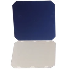
Okay, grabbed cheapest calculator from a store. It turned out to be EATES DC-837, priced below $4. Surprisingly well made, it uses
monocrystallineamorphous PV cell and one AAA battery, connected via a dual diode. This means the calculator should be able to work from as low as 1V, and the PV panel should not cause overvoltage at the same time.The panel size is 12.6x37.8 mm. It looks really inexpensive and is made of glass, protected with paint on the back.


Despite that, the panel works damn good. Such, I was able to get 1.8V from it in a room with dim lights (about 50 lux). At the same time, short circuit current was about 5.9 µA. Exposed to bright sun it resulted in 3.2V open circuit, and 3 mA at short circuit. I reached limit with 1200 lumens torch at 5 cm distance - Voc=3.25V and Isc=7.2 mA.
I did similar measurements for KXOB25-02X8F. This time my torch forced the panel to Voc=5V and Isc=11mA which somewhat differs from datasheet. Results are on the charts below:


-
Okay, grabbed cheapest calculator from a store. It turned out to be EATES DC-837, priced below $4. Surprisingly well made, it uses
monocrystallineamorphous PV cell and one AAA battery, connected via a dual diode. This means the calculator should be able to work from as low as 1V, and the PV panel should not cause overvoltage at the same time.The panel size is 12.6x37.8 mm. It looks really inexpensive and is made of glass, protected with paint on the back.
Despite that, the panel works damn good. Such, I was able to get 1.8V from it in a room with dim lights (about 50 lux). At the same time, short circuit current was about 5.9 µA. Exposed to bright sun it resulted in 3.2V open circuit, and 3 mA at short circuit. I reached limit with 1200 lumens torch at 5 cm distance - Voc=3.25V and Isc=7.2 mA.
I did similar measurements for KXOB25-02X8F. This time my torch forced the panel to Voc=5V and Isc=11mA which somewhat differs from datasheet. Results are on the charts below:
@Mishka Looks very promising!
Thanks for posting the charts and the photo. I tried googling the "SC-1338-4" but found no datasheet, no sellers, nothing. I'm guessing the SC probably stands for "solar cell". Is it by any chance 13mm x 38mm in size? I'm only guessing, but perhaps the 4 is a reference to 4v, which is perhaps the voltage at maximum solar illumination. In that case, what appears to be a part number ("SC-1338-4") is actually just a generic description of the part, not a true manufacturer part number.
The only other clue as to which solar cell is might be is perhaps a barely visible logo in your photo of the cell. The logo looks like the mirror image of "CAT" with a kind of triangle pushing up the bottom of the "A" letter.
By the way, it looks like an interesting source for truly tiny scavenged solar cells might be solar watches:

That solar cell looks tinier than any that I've ever seen for sale. -
@Mishka Looks very promising!
Thanks for posting the charts and the photo. I tried googling the "SC-1338-4" but found no datasheet, no sellers, nothing. I'm guessing the SC probably stands for "solar cell". Is it by any chance 13mm x 38mm in size? I'm only guessing, but perhaps the 4 is a reference to 4v, which is perhaps the voltage at maximum solar illumination. In that case, what appears to be a part number ("SC-1338-4") is actually just a generic description of the part, not a true manufacturer part number.
The only other clue as to which solar cell is might be is perhaps a barely visible logo in your photo of the cell. The logo looks like the mirror image of "CAT" with a kind of triangle pushing up the bottom of the "A" letter.
By the way, it looks like an interesting source for truly tiny scavenged solar cells might be solar watches:
That solar cell looks tinier than any that I've ever seen for sale.@NeverDie You're absolutely right. The cell size is 12.6x37.8 mm which explains 1338. I also agree with your guess on 4V. The CAT is just reflection of my phone.
Well, I'm impressed that a noname manufacturer managed to make such a useful cell. BTW calculator consumption is roughly 5 µW - pretty neat too :)
Regarding solar watches - they should be fine to charge battery, but I'm in doubt they have enough capacity to power on anything so advanced like nRF52 - I hope should be feasible with the SCNE.
Grr, the boards are out of radar - last track is 2019 December, 29.
-
@Mishka Looks very promising!
Thanks for posting the charts and the photo. I tried googling the "SC-1338-4" but found no datasheet, no sellers, nothing. I'm guessing the SC probably stands for "solar cell". Is it by any chance 13mm x 38mm in size? I'm only guessing, but perhaps the 4 is a reference to 4v, which is perhaps the voltage at maximum solar illumination. In that case, what appears to be a part number ("SC-1338-4") is actually just a generic description of the part, not a true manufacturer part number.
The only other clue as to which solar cell is might be is perhaps a barely visible logo in your photo of the cell. The logo looks like the mirror image of "CAT" with a kind of triangle pushing up the bottom of the "A" letter.
By the way, it looks like an interesting source for truly tiny scavenged solar cells might be solar watches:
That solar cell looks tinier than any that I've ever seen for sale.@NeverDie said in 💬 The Harvester: ultimate power supply for the Raybeacon DK:
That solar cell looks tinier than any that I've ever seen for sale.
https://www.sparkfun.com/products/9541
Not sure where to go with this though :)
-
Maybe the reason solar cells like the SC-1338-4 are so elusive to find in the usual parts market is that the manufacturer is basically just buying a relatively cheap 5x5 or 6x6 inch slice of monocrystal that probably looks like:
and then carefully breaking it into bits of such a size that when wired together they exactly fit whatever net size the buyer wants. Though I've never tried it, I presume that you or I could be doing very small scale "manufacturing" ourselves if we were so inclined. Obviously some people make their own DIY 100w panels this way, but from what I've seen those people do so by soldering foil tapes across the front face of the monocrystalline slices, which presumably these cells would be too small to do. Hmmmm...., this now has me curious as to exactly how the bits get wired together. Anyway, provided they're not too hard to make, the upside to DIY'ding small solar cell planels would be getting any size/voltage combination we want plus freedom from having to scavenge pre-made cells from pricier consumer products. -
@NeverDie said in 💬 The Harvester: ultimate power supply for the Raybeacon DK:
That solar cell looks tinier than any that I've ever seen for sale.
https://www.sparkfun.com/products/9541
Not sure where to go with this though :)
@Mishka Looks as though an array of BPW34 can actually be packaged together fairly tightly.

It still wastes some real estate, but not as badly as what I had imagined.I suspect they wouldn't do well under indoor LED lighting though, as they seem to have peak sensitivity at around 900nm, which is infrared.
-
Okay, grabbed cheapest calculator from a store. It turned out to be EATES DC-837, priced below $4. Surprisingly well made, it uses
monocrystallineamorphous PV cell and one AAA battery, connected via a dual diode. This means the calculator should be able to work from as low as 1V, and the PV panel should not cause overvoltage at the same time.The panel size is 12.6x37.8 mm. It looks really inexpensive and is made of glass, protected with paint on the back.
Despite that, the panel works damn good. Such, I was able to get 1.8V from it in a room with dim lights (about 50 lux). At the same time, short circuit current was about 5.9 µA. Exposed to bright sun it resulted in 3.2V open circuit, and 3 mA at short circuit. I reached limit with 1200 lumens torch at 5 cm distance - Voc=3.25V and Isc=7.2 mA.
I did similar measurements for KXOB25-02X8F. This time my torch forced the panel to Voc=5V and Isc=11mA which somewhat differs from datasheet. Results are on the charts below:
@Mishka The specs on the fx-260 solar calculator says it needs at least 50 lux for adequate power, but Dave Jones tested it on youtube and found that 20 lux was sufficient. Unfortunately, he didn't measured the shorted current, so it's hard to know how it compares to the cell on the solar calculator that you tested.
-
@Mishka The specs on the fx-260 solar calculator says it needs at least 50 lux for adequate power, but Dave Jones tested it on youtube and found that 20 lux was sufficient. Unfortunately, he didn't measured the shorted current, so it's hard to know how it compares to the cell on the solar calculator that you tested.
@NeverDie The cell probably is not so sophisticated as the one installed in the fx-260. Also, from four visible sections only three are working. Sigh.
It seems the calculator can acceptably work as long as it supplied with 1.3V or more. This roughly estimates to 40 lux for this particular PV cell. However, the display is the resource hog - every additional digit causes voltage drop. Usable number of digits - five or less. After reset the calculator draws 3µA. Every "8" adds up 0.1µA thus reaching PV short circuit values very soon. The IC seems completely unregulated - at higher voltages it draws proportionally more, up to 1mA.
It's also possible to gain little bit more power (about 70mV) if bypass polarity protection diode. However, it might be rather better to employ 10µF capacitor to compensate for keypress actions. With 92µF it's also possible to enter longer numbers, but you have to type them fast, then store the number in memory, then quickly clear display and wait until the capacitor charges. Now you can type another number, press operation, and, finally, MR and = to calculate result :call_me_hand:
-
@NeverDie The cell probably is not so sophisticated as the one installed in the fx-260. Also, from four visible sections only three are working. Sigh.
It seems the calculator can acceptably work as long as it supplied with 1.3V or more. This roughly estimates to 40 lux for this particular PV cell. However, the display is the resource hog - every additional digit causes voltage drop. Usable number of digits - five or less. After reset the calculator draws 3µA. Every "8" adds up 0.1µA thus reaching PV short circuit values very soon. The IC seems completely unregulated - at higher voltages it draws proportionally more, up to 1mA.
It's also possible to gain little bit more power (about 70mV) if bypass polarity protection diode. However, it might be rather better to employ 10µF capacitor to compensate for keypress actions. With 92µF it's also possible to enter longer numbers, but you have to type them fast, then store the number in memory, then quickly clear display and wait until the capacitor charges. Now you can type another number, press operation, and, finally, MR and = to calculate result :call_me_hand:
@Mishka This youtube video ranks the various different types of solar cell technologies:
https://www.youtube.com/watch?v=8t_DFI4O6v4According to it, the Spectrolab XTE-LILT would be the highest performing, and as a bonus it does its best when under low light conditions, where it has 37% efficiency--head and shoulders above any other brand. Not quite double the performance of the best monocrystals, but almost. However, so far I haven't found it for sale anywhere.
-
@Mishka This youtube video ranks the various different types of solar cell technologies:
https://www.youtube.com/watch?v=8t_DFI4O6v4According to it, the Spectrolab XTE-LILT would be the highest performing, and as a bonus it does its best when under low light conditions, where it has 37% efficiency--head and shoulders above any other brand. Not quite double the performance of the best monocrystals, but almost. However, so far I haven't found it for sale anywhere.
@NeverDie Well, looks like that is the space mission panel :space_invader: :space_invader: :space_invader: Won't be cheap anyway. On the other hand recently I seen a lot of news about so called nighttime photovoltaic power, who knows how fast it can be delivered to market.
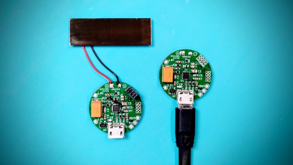
In a meanwhile, I had a chance to play with the Harvester board. Please don't consider everything below as any serious test or a comprehensive review - I just rather tried to understand how the modules are working and what can I get from them.
Following our prior discussion, I've assembled one board in buck-boost mode (the original PCB), and have tweaked another one to the boost configuration. The only solar panels I have are:
- IXYS KX0B25-02X8F. Single panel is annoyingly weak so I connected two of them in series.
- The SCNE SC-1338 from the test above.
- SORBO SB-3077. A big (79x40) panel from solar torch. Didn't tested it like the other two, but noticed about 6V from it.
For the load there is 1500µF 4V tantalum capacitor installed. V_uvp threshold has been set to 2.2V, and V_eoc to 3.2V. Please also note, the MPPT resistor values were set to V_oc=12V (which is too high for all the tested panels) and no adjustments were made to them for any of the tests.
Most of the tests I made in the evening at home where LED lights are the most common source. I used light sensor on my phone to measure light illuminance. Looks like it gives more or less sensible values; such, 50 lux corresponds to a dim light, 250 lux is an office light or indoors illuminance in cloudy day, 1000 lux is outdoors light in cloud day - similar values I've seen in tables over the Internet. After checking illuminance I placed solar panels in the same area and measured most important voltages:
- V_pv - PV panel voltage when it is under load (but see my comments)
- V_store - voltage at the spv1050 store capacitors (2x47µF)
- V_out - voltage on the output capacitor (1500µF)
For low light conditions I waited several minutes for the capacitors to charge and read values only when the system became saturated (or at least look so). Results and my notes are represented in the following table:
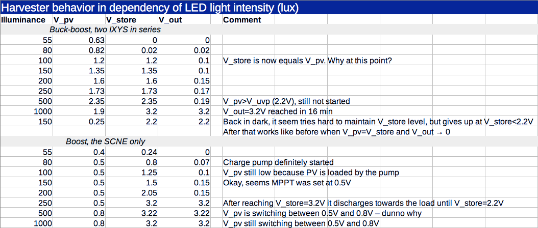
The spv1050 datasheet provides quite detailed description on how it works. The only interesting question was - what happens in buck-boost mode if the harvester cannot maintain V_store voltage anymore due to low illuminance. I found that store and the load will be connected as long as V_out>2.2V. After that, spv1050 will shut down the DC/DC and connect PV to the store. I think DC/DC was on because panel voltage raises up from 0.25V to 0.52V when the store disconnects from the load. Why is it 2.2V and not 2.6V as specified in the datasheet, I don't know.
Another interesting test was how much time it will require to charge the 1500µF capacitor to 3.2V. For that I tried different panels with both buck-boost and boost boards. Please note, since the boost board has 4V limit (due to the tantalum capacitor) and pair of the IXYSes are capable to produce up to 8V, I've skipped this couple. The results are in the table below:
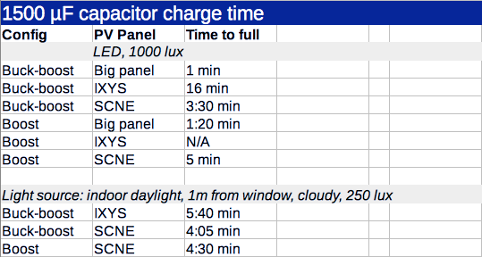
You was absolutely right when expressed the concern on the SolarBit panels - they work much better in the sunlight. The SCNE seem also prefers full spectrum to my LEDs.
Evaluate whether this is a good or bad result is possible when considering the load itself. Accordingly to the Nordic, the nRF52840 will consume about 32µC
per heavyweight BLE event, for example, when running at 2.2V (lowest possible value for the spv1050) and sending +8dBm advertisements. For tiny packets it may be as low as 5µC.The tantalum capacitor stores 1500µF*3.2V = 4800µC - exactly this amount was delivered by the spv1050. This roughly equals to 150 advertisements, or 960 connection packets. If ignore other waste (like sleeping current) and assume 5 minutes as an average result on SCNE-alike panel (indoors, daylight), the system should be able to advertise once every two seconds or send small data packets once every 1/3 second without discharging a battery.
Of course, more light means more power, and there is the night too, but with proper panel and correct location I think it should be possible to maintain positive power balance.
So which configuration to prefer - boost or buck-boost? I still have no simple answer.
The boost is good when you're working in low-light conditions and can keep it low-voltage. I also have impression that the spv1050 is sensitive to the current it can get from a panel. Therefore a couple of single cell panels (i.e low voltage, high current) might be the right choice. On the other hand, it's risky to attach high voltage panels to the boost harvester - neither battery not capacitor will tolerate 6V.
The buck-boost configuration has no such drawback - any panel you may find on attic will very likely to work. Another advantage you might have noticed is that it delivers faster. When fast is fast enough - it depends. But in the low-light when it may took up to 30 minutes to charge a 1500µF capacitor the boost advantage is not so obvious.
-
And couple of words about the Harvester LDO - it works. Also, being connected right to the spv1050 store it could be used to bootstrap the harvester, but if connected full time it will soak about 8µA which is too much for a battery powered board. So still kinda hack, and its primary purpose is to supply the board via USB.
-
Your results are consistent with what I've seen with other harvesters.
- Their #1 goal is to get out of the cold boot mode and to a voltage level where regular electronics can power up, resulting in much more efficient energy harvesting. So, until that minimum voltage is reached, they typically keep all their energy and don't output any. I think that's the right approach, so I have no beef with that.
- I'm not a fan of built-in LDO's either, and for the same reason: in a marginal situation, you don't want to waste any more operational or quiescent current than you have to.
You might enjoy this eevblog video, where the Dave Jones measurements show that the FX260 can handily power its LCD display in idle mode with just 2v and 2ua, and just barely so at 1v and 1.5ua:
It seems to keep its memory alive, for awhile at least, on less than that after the LCD display has gone blank.
I've read that TI made a series of calculators (mostly in the 1980's) called the "anylite" series, which were designed to function without a battery in pretty much even dim indoor light. They used bigger than average solar cells. Asdie from their size, I'm not sure if there was anything special about them. Maybe. I haven't tried one myself, but I suspect so. However, It appears to me that these days though TI has gone the "hybrid" route of stuffing a battery in there, and the size of their solar cell is a lot smaller now. I'm not sure what the value of that is, other than simply extending battery life. The FX260 is one of the few that still offer the solar-only with no battery option. Its LCD display is quite crisp, so it doesn't appear to suffer from doing so.
@NeverDie What I meant is that in addition to internal LDOs in the SPV1050, there is also the MIC5205 3.2V which is sourced from the USB (can accept up to 16V). This LDO output can be connected to the spv1050 store capacitors via relevant solder jumper on the board bottom, and when connected and not powered it draws about 8µA from the store. So the jumper is kind of requirement.
I've enjoyed the calculators video. BTW my calculator from which I took the solar panel has similar characteristics. Regarding reuse of calculator panels, first of all they must match the application voltage. If speaking about the nRF52, it has to be 1.8V to 3.6V (or up to 5.5V), but a small panel can't supply it under load. Also, the radio can draw up to 16 mA which is possible only with larger panels. Of course, a capacitor can fix online use of a solar panel, but in order to work with lights off a secondary battery required, hence the solar charger.
And now it runs out into a game of coulombs. Today I've tested the boards in direct sun light. They charge the 1500µF capacitor in few seconds and then just idling. It looks like this power excess is more suitable for a battery rather a small capacitor. But a 2032 size supercapacitor could also make it. It looks slightly more interesting strategy to fast charge battery when you can and then work from the battery, than struggle to charge the battery in the lowest possible conditions and hence limit charging speed. Please also note, it is usually easier to build high-voltage panels rather high-current ones.
Anyhow, there are too many influential factors so a practical test is required. I think I have ot try two competitive configurations placed in exactly the same environment:
- 2 x KXOB25-02X8F panels (5.53V, 6.3 mA) and the buck-boost board
- 2 x KXOB25-05X3F panels (2.07V, 19.5 mA) and boost only board
Hello! It looks like you're interested in this conversation, but you don't have an account yet.
Getting fed up of having to scroll through the same posts each visit? When you register for an account, you'll always come back to exactly where you were before, and choose to be notified of new replies (either via email, or push notification). You'll also be able to save bookmarks and upvote posts to show your appreciation to other community members.
With your input, this post could be even better 💗
Register Login