Battery powered latching relay node
-
Hi,
I am trying to build a battery (2xAA) powered node that will control a 3V latching relay (http://en.hf-relay.com/uploadfile/2019/0703/20190703021713865.pdf) single coil. The relay is drived by a H bridge (http://www.ti.com/lit/ds/symlink/drv8833.pdf). Does anyone have a working code? Programming is not my strength, I was thinking to reset (turn OFF) the relay everytime Arduino will start and to turn ON/OFF with function call:
void RelayON()
{
digitalWrite(7, HIGH);
delay(50);
digitalWrite(7, LOW);
}The last part would be to have it run in smartSleep and wake up when state change request is sent by gateway (as far as I read this is not possible).
If you have any suggestions please let me know.
Thanks!
@iancu Here you see part of a schematic which I created to control a latching relay:
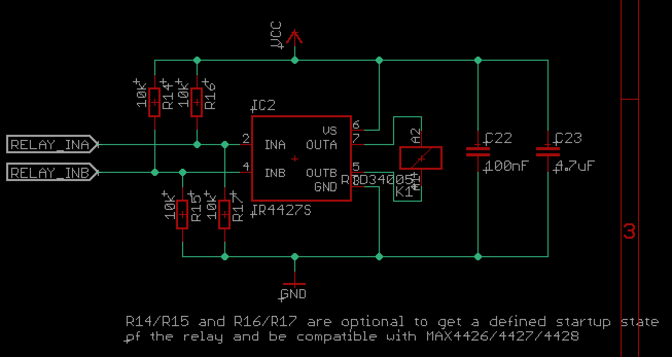
It uses a IR4427S Mosfet driver to drive the relay coils and allows me to drive the coil in both directions.
The relay is a RTD34005.Basically the code comes down to:
#define RELAY_ON              (true)
#define RELAY_OFF             (false)
#define RELAY_STARTUP_STATE   RELAY_OFF
#define RELAY_INA_PIN         (A0)
#define RELAY_INB_PIN         (A1)
#define RELAY_SET_TIME_MS     (30)

// ....


static void switchRelay( const bool on )
{
    Serial.print(F("Relay ")); Serial.println( on ? F("ON") : F("OFF"));
    digitalWrite(RELAY_INA_PIN, on ? LOW : HIGH);
    digitalWrite(RELAY_INB_PIN, on ? HIGH : LOW);
    delay(RELAY_SET_TIME_MS);
    digitalWrite(RELAY_INA_PIN, LOW);
    digitalWrite(RELAY_INB_PIN, LOW);
}

// ...

void setup()
{
  // Setup relay and force to defined state
  digitalWrite(RELAY_INA_PIN, LOW);
  digitalWrite(RELAY_INB_PIN, LOW);
  pinMode(RELAY_INA_PIN, OUTPUT);
  pinMode(RELAY_INB_PIN, OUTPUT);

  // Immediately switch relay off
  switchRelay( false );
}
Then anywhere from your code you just call switchRelay( true ) to switch it on or switchRelay( false ) to switch off again.
I think your issue is mainly that you need 2 inputs to be able to control the direction of the current through the coil of the relay, otherwise you won't be able to open and close it.
-
@iancu Here you see part of a schematic which I created to control a latching relay:
It uses a IR4427S Mosfet driver to drive the relay coils and allows me to drive the coil in both directions.
The relay is a RTD34005.Basically the code comes down to:
#define RELAY_ON              (true)
#define RELAY_OFF             (false)
#define RELAY_STARTUP_STATE   RELAY_OFF
#define RELAY_INA_PIN         (A0)
#define RELAY_INB_PIN         (A1)
#define RELAY_SET_TIME_MS     (30)

// ....


static void switchRelay( const bool on )
{
    Serial.print(F("Relay ")); Serial.println( on ? F("ON") : F("OFF"));
    digitalWrite(RELAY_INA_PIN, on ? LOW : HIGH);
    digitalWrite(RELAY_INB_PIN, on ? HIGH : LOW);
    delay(RELAY_SET_TIME_MS);
    digitalWrite(RELAY_INA_PIN, LOW);
    digitalWrite(RELAY_INB_PIN, LOW);
}

// ...

void setup()
{
  // Setup relay and force to defined state
  digitalWrite(RELAY_INA_PIN, LOW);
  digitalWrite(RELAY_INB_PIN, LOW);
  pinMode(RELAY_INA_PIN, OUTPUT);
  pinMode(RELAY_INB_PIN, OUTPUT);

  // Immediately switch relay off
  switchRelay( false );
}
Then anywhere from your code you just call switchRelay( true ) to switch it on or switchRelay( false ) to switch off again.
I think your issue is mainly that you need 2 inputs to be able to control the direction of the current through the coil of the relay, otherwise you won't be able to open and close it.
-
Hi,
I am trying to build a battery (2xAA) powered node that will control a 3V latching relay (http://en.hf-relay.com/uploadfile/2019/0703/20190703021713865.pdf) single coil. The relay is drived by a H bridge (http://www.ti.com/lit/ds/symlink/drv8833.pdf). Does anyone have a working code? Programming is not my strength, I was thinking to reset (turn OFF) the relay everytime Arduino will start and to turn ON/OFF with function call:
void RelayON()
{
digitalWrite(7, HIGH);
delay(50);
digitalWrite(7, LOW);
}The last part would be to have it run in smartSleep and wake up when state change request is sent by gateway (as far as I read this is not possible).
If you have any suggestions please let me know.
Thanks!
@iancu said in Battery powered latching relay node:
The last part would be to have it run in smartSleep and wake up when state change request is sent by gateway (as far as I read this is not possible).
As Electric pointed out, when it is sleeping the radio is turned off and it's not possible to listen for communication. How quickly do you need to be changing the relay state? Unless you can be sleeping almost all the time, you may have a problem. If you can wake up for a second or two every 5 or 15 minutes and check, that's much different than if you need to respond to a light switch within one second. You need to know how much power is used while sleeping, then how much is used to wake and check if a change is needed, then go back to sleep. Do the math based on how often you need to be checking.
-
@iancu said in Battery powered latching relay node:
The last part would be to have it run in smartSleep and wake up when state change request is sent by gateway (as far as I read this is not possible).
As Electric pointed out, when it is sleeping the radio is turned off and it's not possible to listen for communication. How quickly do you need to be changing the relay state? Unless you can be sleeping almost all the time, you may have a problem. If you can wake up for a second or two every 5 or 15 minutes and check, that's much different than if you need to respond to a light switch within one second. You need to know how much power is used while sleeping, then how much is used to wake and check if a change is needed, then go back to sleep. Do the math based on how often you need to be checking.
@Grubstake that sleep time is too much, even 2 seconds delay is not good for me. But, last night I got an idea, so I will supply the whole node with 3V. I was thinking to supply the NRF24 directly from the battery and use it as an interrupt when the gateway will transmit. According to some google-ing the stand-by current of the NRF24 is pretty low. Could this work? Do you know if the IRQ pin is used for something in mysensors?
PS: @Yveaux while loop ideea did not work as expected
-
@iancu Here you see part of a schematic which I created to control a latching relay:
It uses a IR4427S Mosfet driver to drive the relay coils and allows me to drive the coil in both directions.
The relay is a RTD34005.Basically the code comes down to:
#define RELAY_ON              (true)
#define RELAY_OFF             (false)
#define RELAY_STARTUP_STATE   RELAY_OFF
#define RELAY_INA_PIN         (A0)
#define RELAY_INB_PIN         (A1)
#define RELAY_SET_TIME_MS     (30)

// ....


static void switchRelay( const bool on )
{
    Serial.print(F("Relay ")); Serial.println( on ? F("ON") : F("OFF"));
    digitalWrite(RELAY_INA_PIN, on ? LOW : HIGH);
    digitalWrite(RELAY_INB_PIN, on ? HIGH : LOW);
    delay(RELAY_SET_TIME_MS);
    digitalWrite(RELAY_INA_PIN, LOW);
    digitalWrite(RELAY_INB_PIN, LOW);
}

// ...

void setup()
{
  // Setup relay and force to defined state
  digitalWrite(RELAY_INA_PIN, LOW);
  digitalWrite(RELAY_INB_PIN, LOW);
  pinMode(RELAY_INA_PIN, OUTPUT);
  pinMode(RELAY_INB_PIN, OUTPUT);

  // Immediately switch relay off
  switchRelay( false );
}
Then anywhere from your code you just call switchRelay( true ) to switch it on or switchRelay( false ) to switch off again.
I think your issue is mainly that you need 2 inputs to be able to control the direction of the current through the coil of the relay, otherwise you won't be able to open and close it.
-
@iancu stand-by current for the nrf24 is indeed low, but the radio cannot receive in that mode, it must be in receive mode, which consumes about 13mA.
@mfalkvidd Thanks for the info! Then my idea is not worth the trouble (would have to change the batteries too often).
A good day to everyone! -
I still don't understand why people are still bothering to use NRF24l01...it's old tech nowadays :smile: . Well I get that it's cheaper and bla, bla but when it comes to performance and tuning things up it gets harder imho. Not to forget that you still need another MCU in order to make it work thus increasing BOM and complexity (yes, yes I know why some prefer "decoupled" systems, but still...)
Why not use NRF52832 which is a much more compact solution and let's face it more efficient than the old NRF24L01. Oh and let's not forget that it has a MCU inside also.
I think the list of advantages is obvious:
- More TX power: 4dbm compared to 0dbm.
- Incorporated MCU
- Incorporated DC-DC converter which when enabled will reduce the current consumption in both TX and RX mode (7.5mA in TX mode and 5.4mA in RX mode - this is only for the radio subsystem)
Simplified design when using an already available module like the CDEBYTE or CDSNET from Aliexpress (just search for nrf52832 cdebyte or cdsnet) is also a plus. Those modules are really cheap now - around 3$. Oh and it needs to have those external components (inductors, caps) to be able to use the internal DC-DC converter - the CDEBYTE or CDSNET modules have it.
Now back to this topic main discussion regarding battery powered nodes which need to be pretty responsive no? Well it's not that easy using MySensors to accomplish this - I may be wrong but I tried this for one of my projects and no matter what techniques I used I couldn't achieve the desired results.
Why? Because MySensors it's not designed to create responsive battery powered nodes - please do correct me here @mfalkvidd if I'm wrong. By responsive I mean to make it respond in a time window of <= 1s.@iancu If designing pretty responsive and battery powered nodes then Bluetooth LE is your best bet. I know that it's not MySensors but only BLE can achieve that as far as I know (NRF52832 supports BLE also which is yet another advantage).
I know that this deviates from MySensors and it's not that have something with this project - it's a really great project but we have to know its limitations (as of now at least).
Another alternative would be LORA modules which this project supports also and which have lower RX current because this is the state you would want to stay in most of the time (NRF52832 has it pretty low with the internal DC-DC enabled). But I'm not familiar with LORA modules and from what I've read the TX time cand get very high depending on the modulation speed which is not ideal also.
So what do we need in the end for MySensors: radio modules with very low RX current and fast TX time. Do they exist? I'm not quite sure to be honest (excluding lots of marketing stuff). Faster TX time means also a faster modulation speed/scheme which is achievable even by NRF24l01 so I don't think this is an issue nowadays.
When it comes to MySensors I think a good start is the NRF52832 based modules at least but it won't guarantee the responsiveness that you're looking for @iancu - for that you need a better software stack and radio protocols also imho. -
@iancu
Usually it's best to have an uninterruptible power supply when it comes to building actuators because you want it to "act" all the time. Using batteries for such a thing I wouldn't say it's a reliable choice on the long term.
Imagine what would happen if you do this for a light switch and you come home one day and you find yourself in a situation where you cannot turn on the lights...Of course this very much depends on the final application but still in my opinion actuators should be always powered. -
@mtiutiu Thank you for the information! I will give it a try with the bluetooth module.
I use Home Assistant as the controller and store the relay state in the EEPROM (according to the relay example) and on top of that I have configured the node to send updates of the state (taken form EEPROM) to home assistant periodically.
Hello! It looks like you're interested in this conversation, but you don't have an account yet.
Getting fed up of having to scroll through the same posts each visit? When you register for an account, you'll always come back to exactly where you were before, and choose to be notified of new replies (either via email, or push notification). You'll also be able to save bookmarks and upvote posts to show your appreciation to other community members.
With your input, this post could be even better 💗
Register Login