💬 The Harvester: ultimate power supply for the Raybeacon DK
-
@Mishka said in 💬 The Harvester: ultimate power supply for the Raybeacon DK:
@NeverDie So when TPL5110 has passed the boot phase does it work after that?
Ah, good question. Then it seems to work just fine. I had it waking once every 10 seconds and weakly flashing an amber LED, all on just 88na of collected solar current. Essentially, the capacitor voltage would drop to just below the forward voltage of the LED during the flash (effectively self terminating the flash duration) and then it would charge back up from there.
@NeverDie Oh, nice! It's interesting that the full circle including oscillator consumes so low power. It seems really possible to build a discrete harvesting circuit which can collect enough charge to execute a single duty cycle of an MCU.
Such, assuming (88-35) nA/s = 53 nC charge it will require less than 5 minutes and 22 µF capacitor in order to shot a single BLE event from an nRF52 MCU. And that's at so ridiculous low light. Quite awesome, I think.
The only issue is that the timer can't optimize it for faster charge, but a voltage driven latch could.
-
@NeverDie Oh, nice! It's interesting that the full circle including oscillator consumes so low power. It seems really possible to build a discrete harvesting circuit which can collect enough charge to execute a single duty cycle of an MCU.
Such, assuming (88-35) nA/s = 53 nC charge it will require less than 5 minutes and 22 µF capacitor in order to shot a single BLE event from an nRF52 MCU. And that's at so ridiculous low light. Quite awesome, I think.
The only issue is that the timer can't optimize it for faster charge, but a voltage driven latch could.
@Mishka Just FYI, in my experiment I drove the LED directly from the DRV pin (I didn't use a MOSFET), and I didn't bother with setting the DONE pin, since I wasn't using a MCU. That gave a maximum possible flash duration of 50ms once every 10 seconds, but like I said, it self-terminated before the full 50ms was up because the capacitor voltage dropped below the forward voltage of the LED. Using a mosfet and an MCU, as intended, would give a little more control, since the the MCU could issue a DONE signal.
So, yeah, it really is impressive what can be done with so little light, and it could actually go with even less light and a longer charge time, provided the startup hurdle can be gotten past.
Unfortunately, the XC6136 doesn't yet seem to be widely available at the the all the different possible voltages that can be detected. Digikey doesn't have any, and mouser has only just 3 different types. Perhaps that will improve in the future.
So, perhaps this is a case where powering the TPL5110 from a primary cell would be an acceptable "cheat". At just 35na, that primary cell should last a very long time.
-
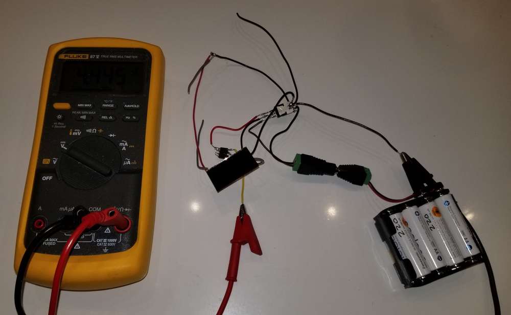
I received a 0.02% accurate 500,000 count DMM that should make measuring changes by small voltage and current amounts a bit easier:
If you're in the market for such a thing, now is a good time to buy, as prices are lower than I have ever seen before and a number of the models previously available from Extech, Brymen, GreenLee, AmProbe and other labels have been discontinued (permanently, it would seem). The models still in production cost 2-3x as much, as did the discontinued models up until fairly recently.
Interestingly, in the dead of night the keychain solar cell can nonetheless pull down 1.3v from a window facing a streetlight that's across the street, as measured with the op amp buffer using a DMM. That amount of light is so low that it registers as 0.2 lux on my lux meter. On the other hand, it also measures 0.2 lux even with the lens cover on, so I think it's below my lux meter's ability to measure it, as the 0.2 lux appears to be just an offset that should be calibrated to zero.
An alternative to the opamp buffer would be to have the solar cell charge a 0.1uF capacitor, which then gets quickly read by an arduino ADC. I haven't wired that up yet, but I expect the results would be about the same.
Or, you could charge a larger capacitor for a longer period of time and perhaps try to snag it with a peak voltage reading when you first connect to it with your DMM. I haven't tried this. I expect it would work, at least to some degree, if you used a big enough capacitor and charged it for long enough, so it might be worthwhile if you have lots of patience.
Interestingly, the typical input resistance for an oscilliscope is only 1 MegaOhm. For a typical DMM, it's 10 MegaOhm, and for an atmega328p ADC, it's 100 MegaOhm. Thus, if measuring 5 volts, the Arduino ADC would experience a 50 nanoOhm drain. That's too high for measuring weakly sourced solar voltages under very dim lighting. 10 gigaohm would be preferable, but then it will take some time to charge up an input capacitor for the ADC to read.
It would be better to leave the input impedance as is but use software to disconnect the input pin when it's not being used. That's certainly possible with an nRF5x, but I'm not aware of that being possible on an Arduino Uno. Is it?
I could connect/disconnect it with a mosfet or a transistor, but then we're back to supplementing the arduino uno with more hardware again, and the voltage drop across such hardware needs to be adjusted for, since the whole point is to get an accurate voltage measurement.
-
I received a 0.02% accurate 500,000 count DMM that should make measuring changes by small voltage and current amounts a bit easier:
If you're in the market for such a thing, now is a good time to buy, as prices are lower than I have ever seen before and a number of the models previously available from Extech, Brymen, GreenLee, AmProbe and other labels have been discontinued (permanently, it would seem). The models still in production cost 2-3x as much, as did the discontinued models up until fairly recently.
Interestingly, in the dead of night the keychain solar cell can nonetheless pull down 1.3v from a window facing a streetlight that's across the street, as measured with the op amp buffer using a DMM. That amount of light is so low that it registers as 0.2 lux on my lux meter. On the other hand, it also measures 0.2 lux even with the lens cover on, so I think it's below my lux meter's ability to measure it, as the 0.2 lux appears to be just an offset that should be calibrated to zero.
An alternative to the opamp buffer would be to have the solar cell charge a 0.1uF capacitor, which then gets quickly read by an arduino ADC. I haven't wired that up yet, but I expect the results would be about the same.
Or, you could charge a larger capacitor for a longer period of time and perhaps try to snag it with a peak voltage reading when you first connect to it with your DMM. I haven't tried this. I expect it would work, at least to some degree, if you used a big enough capacitor and charged it for long enough, so it might be worthwhile if you have lots of patience.
Interestingly, the typical input resistance for an oscilliscope is only 1 MegaOhm. For a typical DMM, it's 10 MegaOhm, and for an atmega328p ADC, it's 100 MegaOhm. Thus, if measuring 5 volts, the Arduino ADC would experience a 50 nanoOhm drain. That's too high for measuring weakly sourced solar voltages under very dim lighting. 10 gigaohm would be preferable, but then it will take some time to charge up an input capacitor for the ADC to read.
It would be better to leave the input impedance as is but use software to disconnect the input pin when it's not being used. That's certainly possible with an nRF5x, but I'm not aware of that being possible on an Arduino Uno. Is it?
I could connect/disconnect it with a mosfet or a transistor, but then we're back to supplementing the arduino uno with more hardware again, and the voltage drop across such hardware needs to be adjusted for, since the whole point is to get an accurate voltage measurement.
@NeverDie said in 💬 The Harvester: ultimate power supply for the Raybeacon DK:
Interestingly, in the dead of night the keychain solar cell can nonetheless pull down 1.3v from a window facing a streetlight that's across the street, as measured with the op amp buffer using a DMM. That amount of light is so low that it registers as 0.2 lux on my lux meter.
It would be interesting to measure voltage when the panel is dead black. Should be possible by wrapping it into paper and then aluminum foil. In theory it should be perfect zero, but connecting wires and the cell itself may work as antenna and hence the opamp may show some bias.
An alternative to the opamp buffer would be to have the solar cell charge a 0.1uF capacitor, which then gets quickly read by an arduino ADC. I haven't wired that up yet, but I expect the results would be about the same.
Yeah, the charge capacitor is part of some ADC implementations. But instead of use of comparators it might be possible to measure charge / discharge time and derive current and voltage from that. Also, knowing the charge current it will be easy to derive time to full charge and select proper capacitor.
It would be better to leave the input impedance as is but use software to disconnect the input pin when it's not being used. That's certainly possible with an nRF5x, but I'm not aware of that being possible on an Arduino Uno. Is it?
From my understanding, input impedance of most of MCU ADC pins (when disabled) are defined by MOSFETs and hence is subject to implementation and input voltage. But with the charge capacitor large enough it should be not an issue, at least as long as the capacitor wasn't connected to the ADC port during the charge (otherwise the impedance must be gigohms in order to be negligible small). Perhaps a mechanical switch could better solve it for the task. And then MCU can be used to measure time to discharge and do the math.
Also, I must note that to charge the capacitor with tens of nanoamps, the harvester control circuit must consume something in picoamps :-) And this makes me think that, first, there must be a reasonable bottom limit, and, second, a combined RF / solar harvester may be an interesting option to go, especially taking in account they can be connected to the same input.
-
@NeverDie said in 💬 The Harvester: ultimate power supply for the Raybeacon DK:
Interestingly, in the dead of night the keychain solar cell can nonetheless pull down 1.3v from a window facing a streetlight that's across the street, as measured with the op amp buffer using a DMM. That amount of light is so low that it registers as 0.2 lux on my lux meter.
It would be interesting to measure voltage when the panel is dead black. Should be possible by wrapping it into paper and then aluminum foil. In theory it should be perfect zero, but connecting wires and the cell itself may work as antenna and hence the opamp may show some bias.
An alternative to the opamp buffer would be to have the solar cell charge a 0.1uF capacitor, which then gets quickly read by an arduino ADC. I haven't wired that up yet, but I expect the results would be about the same.
Yeah, the charge capacitor is part of some ADC implementations. But instead of use of comparators it might be possible to measure charge / discharge time and derive current and voltage from that. Also, knowing the charge current it will be easy to derive time to full charge and select proper capacitor.
It would be better to leave the input impedance as is but use software to disconnect the input pin when it's not being used. That's certainly possible with an nRF5x, but I'm not aware of that being possible on an Arduino Uno. Is it?
From my understanding, input impedance of most of MCU ADC pins (when disabled) are defined by MOSFETs and hence is subject to implementation and input voltage. But with the charge capacitor large enough it should be not an issue, at least as long as the capacitor wasn't connected to the ADC port during the charge (otherwise the impedance must be gigohms in order to be negligible small). Perhaps a mechanical switch could better solve it for the task. And then MCU can be used to measure time to discharge and do the math.
Also, I must note that to charge the capacitor with tens of nanoamps, the harvester control circuit must consume something in picoamps :-) And this makes me think that, first, there must be a reasonable bottom limit, and, second, a combined RF / solar harvester may be an interesting option to go, especially taking in account they can be connected to the same input.
@Mishka said in 💬 The Harvester: ultimate power supply for the Raybeacon DK:
It would be interesting to measure voltage when the panel is dead black. Should be possible by wrapping it into paper and then aluminum foil. In theory it should be perfect zero, but connecting wires and the cell itself may work as antenna and hence the opamp may show some bias.
OK, I'll try it and let you know.
@Mishka said in 💬 The Harvester: ultimate power supply for the Raybeacon DK:
Also, I must note that to charge the capacitor with tens of nanoamps, the harvester control circuit must consume something in picoamps
You're right, there just aren't going to be any control circuits that run on mere pico-amps on a continuous basis, and that sets the limit on how low you can go. It's for that very reason that I'm hoping to find some kind of ultra low current, very low frequency, low voltage self starting circuit that effectively draws almost no current until it starts up. It wouldn't have to start at a precise voltage. Just in a general ballplark. Maybe something like this, except lower voltage than 3v?
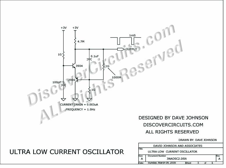
http://www.discovercircuits.com/DJ-Circuits/3na-osc.htm
Seems like it should be possible, given progress in the components since that circuit was drawn, which is now quite a while ago.If so, maybe it could even be used to drive a boost converter, similar to:

and with a high enough voltage, perhaps a voltage multiplier as well:

http://dangerousprototypes.com/blog/2013/07/20/avalanche-pulse-generator-and-some-scope-porn/Basically, the circuit needs to remain inert until enough charge builds up and a trigger gets tripped. And, it needs not to bootlooop even though it ramps up using just very little current. A tall order, I know. Not sure if the right kind of circuit exists, but that's what I'm in the hunt for.
If not a multivibrator, then maybe a ring oscillator. Or, if not that, then a blocking oscillator. And if not that, ...., who knows? There are lots of research papers published where people have been able to do it, but unfortunately a lot of them are IEEE published, and so I don't have access to the details of how it has been done. For sure, a lot of it is instantiated into a CMOS chip, which is beyond my reach anyway, but some of them do seem to use discrete components.
If you have any suggetions, I'm all ears.
-
@Mishka said in 💬 The Harvester: ultimate power supply for the Raybeacon DK:
It would be interesting to measure voltage when the panel is dead black. Should be possible by wrapping it into paper and then aluminum foil. In theory it should be perfect zero, but connecting wires and the cell itself may work as antenna and hence the opamp may show some bias.
OK, I'll try it and let you know.
@Mishka said in 💬 The Harvester: ultimate power supply for the Raybeacon DK:
Also, I must note that to charge the capacitor with tens of nanoamps, the harvester control circuit must consume something in picoamps
You're right, there just aren't going to be any control circuits that run on mere pico-amps on a continuous basis, and that sets the limit on how low you can go. It's for that very reason that I'm hoping to find some kind of ultra low current, very low frequency, low voltage self starting circuit that effectively draws almost no current until it starts up. It wouldn't have to start at a precise voltage. Just in a general ballplark. Maybe something like this, except lower voltage than 3v?
http://www.discovercircuits.com/DJ-Circuits/3na-osc.htm
Seems like it should be possible, given progress in the components since that circuit was drawn, which is now quite a while ago.If so, maybe it could even be used to drive a boost converter, similar to:
and with a high enough voltage, perhaps a voltage multiplier as well:
http://dangerousprototypes.com/blog/2013/07/20/avalanche-pulse-generator-and-some-scope-porn/Basically, the circuit needs to remain inert until enough charge builds up and a trigger gets tripped. And, it needs not to bootlooop even though it ramps up using just very little current. A tall order, I know. Not sure if the right kind of circuit exists, but that's what I'm in the hunt for.
If not a multivibrator, then maybe a ring oscillator. Or, if not that, then a blocking oscillator. And if not that, ...., who knows? There are lots of research papers published where people have been able to do it, but unfortunately a lot of them are IEEE published, and so I don't have access to the details of how it has been done. For sure, a lot of it is instantiated into a CMOS chip, which is beyond my reach anyway, but some of them do seem to use discrete components.
If you have any suggetions, I'm all ears.
@NeverDie said in 💬 The Harvester: ultimate power supply for the Raybeacon DK:
@Mishka said in The Harvester: ultimate power supply for the Raybeacon DK:
It would be interesting to measure voltage when the panel is dead black. Should be possible by wrapping it into paper and then aluminum foil. In theory it should be perfect zero, but connecting wires and the cell itself may work as antenna and hence the opamp may show some bias.
OK, I'll try it and let you know.
@Mishka 8mv was as low as I could take it, but I suspect even then there may have been some slight amount of light getting at it. The room was very dark, but I could make out shapes with night vision, and the backlight on my Fluke 87v was leaking light all over the place, even though I tried to shield it. To really do it properly I'd probably have to set up a wireless link so that I could be in another room to read the voltage. Either that or set up a logger and check it after-the-fact. So, summarizing, I apologize I didn't do a more thorough job, but for being conducted in the middle of a pandemic I did the best that time allows, and besides, 8mv is pretty close to zero, so I hope that answers your question well enough. :) As a cross-check to rule out the possibility of it being an artifact, I'll sometime soon take the measurement in a brief snapshot using an arduino, without the aid of an op-amp, and see how that compares. I'll probably use a load switch to disconnect the arduino so that the solar cell has a chance to charge up a capacitor between readings, and I anticipate that given enough time it will eventually charge up to the open circuit voltage.
Should I start a separate thread for this, or continue it here? It seems that your project is completed, and although this is all relevant, maybe it would be better to split it off? @Mishka Since you're the OP, what's your preference? Continue as is, or fork your thread and continue in a separate thread? I'm enjoying the collaboration, and hope you feel the same. I'm fine with either choice.
-
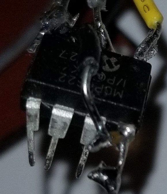
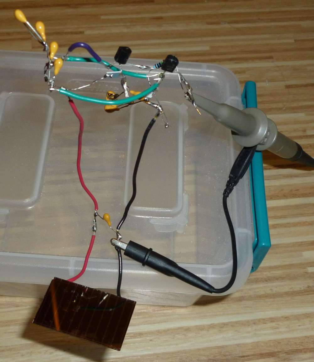
In case anyone is curious, this is the dead-bug setup I used to do the op-amp assisted measurements:
The op-amp calls for a bypass capacitor to be soldered within one millimeter of the input signal, so I soldered a small surface mount ceramic cap directly to that pin and then ran a wire to it from the GND pin. Not sure how well you can see it, but here's a photo of that:
The LDO had similar capacitor requirements, and I was able to solder those directly between its pins:
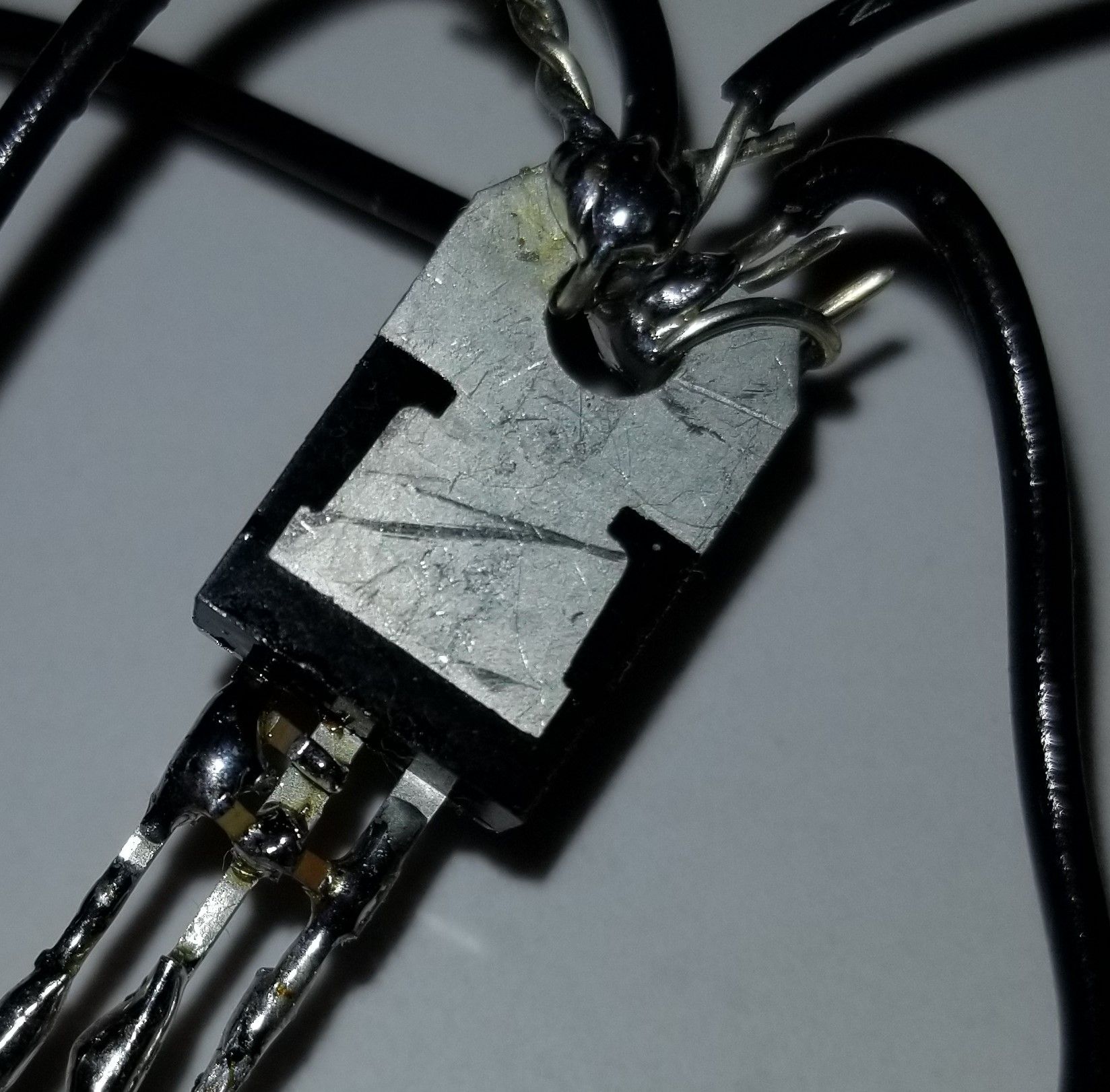
Maybe because of that, despite all the long wires, noise didn't seem to be a problem. The reason for the deadbug design and the DIP op-amp was to avoid any leakage currents that might happen if it were all mounted properly to a protoboard, as I've read accounts from others who have tried doing that but who ran into leakage problems.
So, while I admit it looks awfully scruffy, it doesn't matter, because it's purpose built just to help get accurate open circuit voltage measurements (and short-circuit current measurements with a uCurrent Gold, not shown here).
-
And here is Version 2, which uses an Arduino UNO to and a load switch to measure an E-PEAS solar module that's charging a 100uF capacitor using a solar keychain solar cell. This time I did use a prototype board.
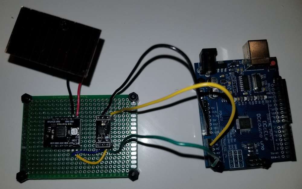
It's too soon to evaluate, but it seems as though it's off to a good start....Edit: nope. I'll have to migrate the Arduino design to dead-bug, because the voltage is only very slowly crawling up. Maybe that's just how it is with this the E-PEAS, or else maybe mounting leakage (the higher the voltage the higher the leakage) is what's causing the drag.
Edit2: confirmed. These measurements were taken at 1 minute intervals, under varying cloud conditions, and it's clearly not able to hold on to the charge the E-PEAS has accumulated on the 100uF ceramic cap:
734, raw = 652, volts = 3.267 735, raw = 689, volts = 3.453 736, raw = 371, volts = 1.859 737, raw = 399, volts = 1.999 738, raw = 445, volts = 2.230 739, raw = 556, volts = 2.786 740, raw = 616, volts = 3.087 741, raw = 671, volts = 3.362 742, raw = 371, volts = 1.859 743, raw = 444, volts = 2.225 744, raw = 510, volts = 2.556 -
I punted on the Arduino and hooked up the E-Peas AEM10941 module to the deadbug op-amp for measurement, as the dead-bug op-amp appears to work flawlessly. The results were: the AEM10941 does build up to a voltage of about 4.135v max when under fairly bright lighting, and then all that disappears and it reverts to starting to charge up again from a voltage of about 1.8v, and it cycles over and over like that. Kinda weird, but that unexpected result may explain the above 1 minute interval readings: probably (?) it wasn't current leakage but instead this kind of cycling that explains the measurements.
Edit: Unfortunately, the AEM10941 breakout board can't seem to rise above 0.352 volts when tested with the same solar cell and same dead-bug op amp assembly under the same 1 flux light source, so I'm afraid I have to label it a FAIL for use in boosting, just by itself, from that particular low light scenario. Given its datasheet, I'm rather disappointed. I did clean the board and my soldered connections pretty thoroughly with IPA, but perhaps there are other leakages inherent in that board, or perhaps the chip itself has limitations that maybe aren't apparent from its datasheet.
Which raises an interesting question: are some types of PCB's less prone than others when it comes to leakage currents? It might make a difference in what kind I order from a PCB fabhouse if some types are better than others. Anyone know?
I didn't test whether the AEM10941 might have some other beneficial use if that barrier is somehow passed, or assisted in being passed, but for now I'm moving on to test some other chips and see how they perform under these conditions to see whether they perform any better and without needing help.
Edit: BQ25504 has no problem charging under the 1 lux light, under the same conditions, even from a starting voltage of zero volts.
Edit2: Well, not quite. Despite a promising start, the BQ25504 peaked at 0.812v and couldn't seem to pull itself above that. It was able to charge up further than the AEM10941, but it hit a ceiling nonetheless. So this time I gave it some bright light to bring its supercap voltage up to 0.814v, and now the voltage appears to be climbing again, al beit slowly. Assuming it is able to continue on its own from this point forward, then my theory is that internally there is a schmitt trigger which is causing this effect: as the voltage slowly rises, the current drain increases up to a peak and then declines again as the voltage continues to rise. At least that is how TI describes typical schmitt trigger behavior in Figure 1 of TI's application report entitled "Understanding Schmitt Triggers": http://www.ti.com/lit/an/scea046/scea046.pdf
Vertical axis is current and horizontal access is voltage.
So, if that peak current drain is greater than the current generated by the solar cell at the 1 lux light level, it simply can't push past it to the other side.Both chips seem rather pathetic if, as seems to be the case, a solar cell alone and without assistance can charge up a capacitor to its open circuit voltage of somewhere around 2.7v but they can't. To be fair, there could be other factors in play, though, like the PCB material type, the dialectric the manufacturer used to impregnate the FR4 to make the PCB, how much humidity had gotten into the FR4 (resulting in extra leakages), component choices as well as layout. That was my earlier hunch, but that hunch may get upended and replaced with the schmitt trigger theory if the BQ25504 continues its upward charge. We shall soon see.
Meanwhile, somewhere I have laying around a BQ25570 on a chinese breakout board, and it might (?) possibly avoid this problem that the other two seem to share....
Edit3: Nope. The BQ25504 simply got stuck again, this time at 0.851v. According to the datasheet, it's still in cold-start mode until the voltage on VSTOR reaches at least 1.6v (or possibly higher), and that matches what I recall about the BQ25504 from earlier experimentation with it: it performs pretty terribly while in cold-start mode.
Punt!
Unfortunately, BQ25570 also remains in cold start mode up to the same 1.6v+ as the BQ25504, so I'm losing optimism that it might be any better... And like the BQ25504, the BQ25570 also requires typically 15uw to get its mojo on, and at 88na of current that just isn't going to happen.
So, there's no rush to test the BQ25570. If the datasheet is right, it's almost certainly another FAIL. :( Judging from the datasheet, the BQ25570 is largely just the BQ25504 mashed together with a buck converter. And the BQ25505 looks about the same as the BQ25504, except with a little bit less quiescent current.What a disappointment! I would have thought that TI had the in-house talent to do a lot better than this.
-
Well, doing a little back of the envelope calculations: if a silver zinc 8mah SR416 primary battery, which is just 4.8mm in diameter and 1.6mm thick, were used to continuously drive a 35na TLV5110 timer, then assuming all 8mah could be extracted and ignoring self discharge, it would last for 26 years. Then consider that a properly designed energy harvesting circuit could relieve the battery from needing to run whenever there is adequate harvested energy available, and the expected lifespan of the system would probably be even longer.
The only purpose of the timer would be to pulse accumulated energy into an off-the-shelf energy harvester, probably none of which can handle extreme low energy accumulation. One maybe can't know what the optimal duty cycle should be, but one could make educated guesses, and perhaps a more refined circuit could even self adapt to some degree.
Anyhow, I'd rather not go that route, but as an exploratory tool, it would be fun to make these harvesters work in "scotopic" darkness and yet still accomplish something useful with whatever energy they can somehow squeeze out of it, all while remaining tiny. :sunglasses:
-
@Mishka said in 💬 The Harvester: ultimate power supply for the Raybeacon DK:
It would be interesting to measure voltage when the panel is dead black. Should be possible by wrapping it into paper and then aluminum foil. In theory it should be perfect zero, but connecting wires and the cell itself may work as antenna and hence the opamp may show some bias.
OK, I'll try it and let you know.
@Mishka said in 💬 The Harvester: ultimate power supply for the Raybeacon DK:
Also, I must note that to charge the capacitor with tens of nanoamps, the harvester control circuit must consume something in picoamps
You're right, there just aren't going to be any control circuits that run on mere pico-amps on a continuous basis, and that sets the limit on how low you can go. It's for that very reason that I'm hoping to find some kind of ultra low current, very low frequency, low voltage self starting circuit that effectively draws almost no current until it starts up. It wouldn't have to start at a precise voltage. Just in a general ballplark. Maybe something like this, except lower voltage than 3v?
http://www.discovercircuits.com/DJ-Circuits/3na-osc.htm
Seems like it should be possible, given progress in the components since that circuit was drawn, which is now quite a while ago.If so, maybe it could even be used to drive a boost converter, similar to:
and with a high enough voltage, perhaps a voltage multiplier as well:
http://dangerousprototypes.com/blog/2013/07/20/avalanche-pulse-generator-and-some-scope-porn/Basically, the circuit needs to remain inert until enough charge builds up and a trigger gets tripped. And, it needs not to bootlooop even though it ramps up using just very little current. A tall order, I know. Not sure if the right kind of circuit exists, but that's what I'm in the hunt for.
If not a multivibrator, then maybe a ring oscillator. Or, if not that, then a blocking oscillator. And if not that, ...., who knows? There are lots of research papers published where people have been able to do it, but unfortunately a lot of them are IEEE published, and so I don't have access to the details of how it has been done. For sure, a lot of it is instantiated into a CMOS chip, which is beyond my reach anyway, but some of them do seem to use discrete components.
If you have any suggetions, I'm all ears.
Hi @NeverDie, thanks a lot for doing the experiments!
Basically, the circuit needs to remain inert until enough charge builds up and a trigger gets tripped. And, it needs not to bootlooop even though it ramps up using just very little current. A tall order, I know. Not sure if the right kind of circuit exists, but that's what I'm in the hunt for.
Yeah, this is would be very interesting to achieve indeed. Looks like the water bucket from aquapark. Unfortunately, have no practical ideas at the moment. Maybe a FET + BJT combo where the FET generates spike of the current which activates the BJT which then drains the input capacitor? The idea here is to utilize the inrush current from the FET before it will be stabilized. A comparator may have higher quiescent current, or may not.
8mv was as low as I could take it, but I suspect even then there may have been some slight amount of light getting at it. The room was very dark...
8 mv is fair enough. So it seems all about the structure of the amorphous cell. Interesting!
Should I start a separate thread for this, or continue it here? It seems that your project is completed, and although this is all relevant, maybe it would be better to split it off? @Mishka Since you're the OP, what's your preference? Continue as is, or fork your thread and continue in a separate thread? I'm enjoying the collaboration, and hope you feel the same. I'm fine with either choice.
Although the discussion went beyond the original project, the topic is very interesting. While most of existing harvesters are aimed at low-voltage sources, it seems that we're trying to address the unique property of a-Si cells to have high-voltage bias in the extremely low light. This is not only enjoying, but might also have (and I hope will do) some practical extension. Of course, if there is a better place for the discussion - it's completely okay to move it, I'll be glad to follow-up there.
Regarding the project, it wasn't finished yet. I'm currently waiting for newest PCBs - they're still based on SPV1050, fully configurable, the components selection is for the boost. Appropriate solar panels are also on the way.
BTW, I had a chance to try the SPV1050 (buck) and nRF52833 with a single one SolarBit I have, no battery attached. In the direct sunlight it works without any issue, even with 1 mA red LED blinking 50% of time. This is definitely not the best setup, so the mentioned PCBs and panels should make it more useful and especially for a cloudy day. Also, for the version 2.0 I'm considering to replace the harvester IC with the AEM1094. I also have somewhat different idea about form-factor, but that's for another topic.
And here is Version 2, which uses an Arduino UNO
Perhaps the right thing would be to charge the capacitor first, and only after that connect it to the Arduino. The Arduino has to read the ADC often so it should be possible to determine highest voltage before it decays.
Unfortunately, the AEM10941 breakout board can't seem to rise above 0.352 volts when tested with the same solar cell and same dead-bug op amp assembly under the same 1 flux light source, so I'm afraid I have to label it a FAIL for use in boosting, just by itself, from that particular low light scenario.
...
Despite a promising start, the BQ25504 peaked at 0.812v and couldn't seem to pull itself above that.From my (perhaps not too careful) review I did earlier in this thread the AEM10941 requires 3 µW input, and the BQ25504 requires 15 µW. Either of those are far beyond the 3V*80nA condition.
Unfortunately, by most of manufacturers a nanoamp source seem usually considered as zero current.
if a silver zinc 8mah SR416 primary battery, which is just 4.8mm in diameter and 1.6mm thick, were used to continuously drive a 35na TLV5110 timer, then assuming all 8mah could be extracted and ignoring self discharge, it would last for 26 years.
Hmm... taking in account those 80 nA collected in 10 seconds will be wasted in one millisecond, and then the next 9.999+10 seconds it will wait for another portion, it sounds like bargaining 35 nA for 40 nA. Well, fair enough! :face_with_cowboy_hat:
-
Hi @NeverDie, thanks a lot for doing the experiments!
Basically, the circuit needs to remain inert until enough charge builds up and a trigger gets tripped. And, it needs not to bootlooop even though it ramps up using just very little current. A tall order, I know. Not sure if the right kind of circuit exists, but that's what I'm in the hunt for.
Yeah, this is would be very interesting to achieve indeed. Looks like the water bucket from aquapark. Unfortunately, have no practical ideas at the moment. Maybe a FET + BJT combo where the FET generates spike of the current which activates the BJT which then drains the input capacitor? The idea here is to utilize the inrush current from the FET before it will be stabilized. A comparator may have higher quiescent current, or may not.
8mv was as low as I could take it, but I suspect even then there may have been some slight amount of light getting at it. The room was very dark...
8 mv is fair enough. So it seems all about the structure of the amorphous cell. Interesting!
Should I start a separate thread for this, or continue it here? It seems that your project is completed, and although this is all relevant, maybe it would be better to split it off? @Mishka Since you're the OP, what's your preference? Continue as is, or fork your thread and continue in a separate thread? I'm enjoying the collaboration, and hope you feel the same. I'm fine with either choice.
Although the discussion went beyond the original project, the topic is very interesting. While most of existing harvesters are aimed at low-voltage sources, it seems that we're trying to address the unique property of a-Si cells to have high-voltage bias in the extremely low light. This is not only enjoying, but might also have (and I hope will do) some practical extension. Of course, if there is a better place for the discussion - it's completely okay to move it, I'll be glad to follow-up there.
Regarding the project, it wasn't finished yet. I'm currently waiting for newest PCBs - they're still based on SPV1050, fully configurable, the components selection is for the boost. Appropriate solar panels are also on the way.
BTW, I had a chance to try the SPV1050 (buck) and nRF52833 with a single one SolarBit I have, no battery attached. In the direct sunlight it works without any issue, even with 1 mA red LED blinking 50% of time. This is definitely not the best setup, so the mentioned PCBs and panels should make it more useful and especially for a cloudy day. Also, for the version 2.0 I'm considering to replace the harvester IC with the AEM1094. I also have somewhat different idea about form-factor, but that's for another topic.
And here is Version 2, which uses an Arduino UNO
Perhaps the right thing would be to charge the capacitor first, and only after that connect it to the Arduino. The Arduino has to read the ADC often so it should be possible to determine highest voltage before it decays.
Unfortunately, the AEM10941 breakout board can't seem to rise above 0.352 volts when tested with the same solar cell and same dead-bug op amp assembly under the same 1 flux light source, so I'm afraid I have to label it a FAIL for use in boosting, just by itself, from that particular low light scenario.
...
Despite a promising start, the BQ25504 peaked at 0.812v and couldn't seem to pull itself above that.From my (perhaps not too careful) review I did earlier in this thread the AEM10941 requires 3 µW input, and the BQ25504 requires 15 µW. Either of those are far beyond the 3V*80nA condition.
Unfortunately, by most of manufacturers a nanoamp source seem usually considered as zero current.
if a silver zinc 8mah SR416 primary battery, which is just 4.8mm in diameter and 1.6mm thick, were used to continuously drive a 35na TLV5110 timer, then assuming all 8mah could be extracted and ignoring self discharge, it would last for 26 years.
Hmm... taking in account those 80 nA collected in 10 seconds will be wasted in one millisecond, and then the next 9.999+10 seconds it will wait for another portion, it sounds like bargaining 35 nA for 40 nA. Well, fair enough! :face_with_cowboy_hat:
@Mishka said in 💬 The Harvester: ultimate power supply for the Raybeacon DK:
Hmm... taking in account those 80 nA collected in 10 seconds will be wasted in one millisecond, and then the next 9.999+10 seconds it will wait for another portion, it sounds like bargaining 35 nA for 40 nA. Well, fair enough!
TI makes a range of different TLP5xxx chips, and Adafruit makes convenient breakout boards for at least two of the different models. I even used one in an earlier leak detection project: https://www.openhardware.io/view/534/Extremely-Simple-Arduino-Pro-Mini-LoRa-Water-Leak-Detector
What I haven't yet tested (and haven't read nor heard) is whether ia TPL5xxx can self excite and start-up normally if powered from the very slowly rising voltage created by a tiny solar cell in weak lighting.
-
I stumbled across this: http://www.prc68.com/I/JouleThief.shtml
which is a fascinating goldmine of information about blocking oscillators and their use in just about every cheap solar circuit you've ever seen or heard of, including some that maybe you haven't. Be that as it may, for tiny panels in ultra low light (1 lux and below), I'm pretty sure they'll need to be spoon fed, just like these commercial chips we've been examining.As for a proper DIY trigger circuit, about 5 years ago David Pilling made some very interesting posts regarding the use of PUTs (programmable unijunction transistors): https://www.davidpilling.com/wiki/index.php/PUT
and on his wiki he built some solar harvesters around that. What I really like and appreciate about his work is that he published ltspice models of his circuits, so it's very easy to download them and run the simulations. Earlier today I emailed David Pilling to see if he'd like to join the discussion here. A lot of technological progress in ultra low power has happened over the last 5 years, and so I think maybe he would be interested and perhaps he'd want to upgrade his circuitry to take advantage of the much lower-voltage/lower-energy components commonly available now that simply didn't exist back then.@Mishka said in 💬 The Harvester: ultimate power supply for the Raybeacon DK:
Hmm... taking in account those 80 nA collected in 10 seconds will be wasted in one millisecond, and then the next 9.999+10 seconds it will wait for another portion, it sounds like bargaining 35 nA for 40 nA. Well, fair enough!
What I forgot to mention in the post directly above was that the tlp5xxx chips can be resistor programmed for much longer cycles than 10 seonds. e.g. the TLP5110 can be set anywhere from 100ms delay all the way up to a 2 hour delay. So, that's a very pliable range for collecting tiny amounts of solar on a cap, which can then be fed into a harvester as a unified kick. The 10 seconds you're referring to just an arbitrary number that I had picked and which just happened to work in the earlier circuit. The time delay could be set much less or much greater than 10 seconds. It's whatever you choose.
I think I'll try a tpl5xxxx timed collector and then pipe the accumulated current into the LTC3508 circuit through an ultra low leakage load switch. Since the LTC3801 needs only 20mv, it should be easy to collect at least that voltage level, even in very dark conditions, using the solar keychain solar cell (amorphous silicon): https://www.openhardware.io/view/732/Extreme-Energy-Harvester So, while the hunt is on for something better and more elegant as a trigger than the crudity of just how much time has passed, this is a brute force approach whose virtue is that it's pretty much guaranteed to work provided that leakage currents are tightly controlled to extremely low levels Fortunately, because of ohm's law, ultra low voltage is likely to make ultra low leakage easier to achieve during the accumulation phase. :grin: What will be interesting is: 1. how big a cap is needed and 2. how long the cycle time needs to be, because boosting extremely low voltages still needs to meet the minimal power requirements (i.e. a lot of current). Unfortunately, nowhere that I can find in the LTC3108 datasheet does it specify the minimum input power to operate. Just the 20mv minimum voltage. Therefore, I'm guessing the minimum power is probably rather high, since companies often hide their bad news by simply not reporting it in the datasheet. Anyhow, I'll just have to derive the minimum power as best I can through experimentation. :face_with_rolling_eyes:
The main downside to the TPL5xxx is that it reads the resistor values exactly once during the startup phase, and then never again. Although that has the benefit of limiting forever after the amount of current the TPL5xxx needs to operate, it also means that you can't easily change the periodicity anytime after the TPL5xxx starts up: even if you change the resistors after it gets going, it never reads them again. Thinking ahead, it might (?) be possible to hack around that limitation by changing the resistor values and then power cycling the TPL5xxx so that it reads the new values and incorporates them. The tradeoff for that result though is the extra circuitry needed to accomplish that. It would be much easier if (?) one of the TPL5xxx variants had a reset pin, so perhaps I'll look soon into whether or not any of them have that feature....
-
I put David Johnson's 3na oscillator circuit:
http://www.discovercircuits.com/DJ-Circuits/3na-osc.htm
into LTSpice and ran the simulation, and it looks promising:
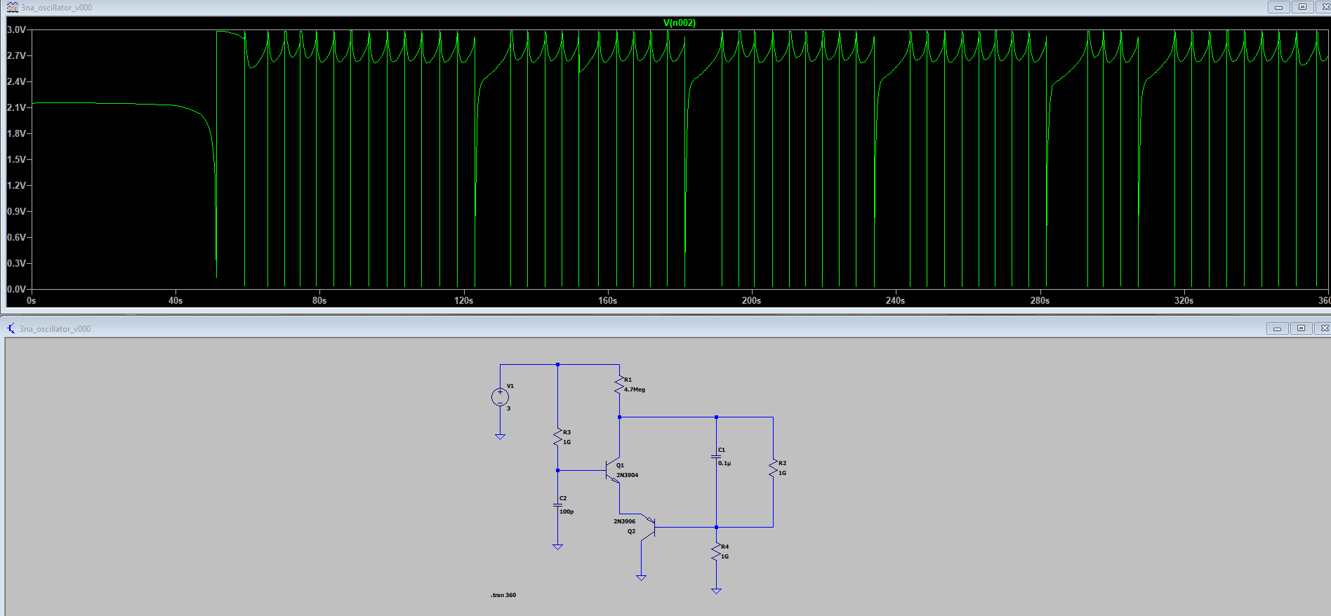
It also runs just fine at 2v. Fairly easy to get a shorter or longer cycle by tweaking the resistor values and/or capacitor values.
The voltage swing is even better than I was expecting: it drops all the way down to around 30 or 40mv. :yum:
Of course, it would be nice if it could run at even lower voltages than 2v. Seems like that should be possible. Anyone have suggestions for which transistors to try for that?
The simulation shows that there's a very nice current pulse of about 4.2ma through Q2 during the very brief discharge phase, so I'm guessing that could drive a buffer transistor to turn on hard, which in turn could, in theory, drive a meaningful load without disturbing the underlying timer circuit. :sunglasses: If that's the architecture, though, there may need to be a separate, isolated capacitor to drive the load that charges up in parallel with the capacitors in this oscillator circuit--unless perhaps there's some way to recycle/reuse the current that gets dumped and otherwise wasted during each discharge.
Or, quite possibly, it could be used to drive a flyback type circuit, in which case I possibly wouldn't need a commercial boost chip at all and could instead do all the boosting with a homemade DIY circuit made out of discrete components. :heart_eyes: That's the promise of what this type of low-level control could grant.
Edit: I posted the LTSpice circuit simulation file for David Johnson's 3 nano-ampere circuit here:
https://github.com/rabbithat/3nanoAmpOscillatorEdit2: I anticipate a potential problem though: the 3na oscillator has very high input impedance. PV cells are modeled as having a shunt resistance, and unless that shunt resistance is exceptionally high, then most of the generated solar cell current won't be entering into the oscillator but will instead be lost as wasted current through the shunt resistor. I'm hoping that doesn't preclude the oscillator from working, but it might if that reduced current translates into reduced voltage at the inputs to the oscillator. The best case scenario would be that the oscillator simply has a much longer cycle time with the PV cell as compared to a battery. In any case, shunt resistance doesn't seem especially easy to measure, so one strategy would be to just build the circuit and see how it works with the target PV cell rather than fuss too much over constructing an accurate equivalent circuit to plug into the simulator.
Edit3: Good news. Using the method published in IEEE to calculate PV shunt resistance (https://ieeexplore.ieee.org/document/1483817), I calculate the shunt resistance on the keychain solar cell to be 30,681,818 ohms. So, more than likely the oscillator will work when hooked up to it. This also finally explains why these solar cells perform so well at even ultra low lighting conditions.
This thread seems to have petered out, so I guess that's the end of it. It was nice while it lasted. :-)
-
I put David Johnson's 3na oscillator circuit:
http://www.discovercircuits.com/DJ-Circuits/3na-osc.htm
into LTSpice and ran the simulation, and it looks promising:
It also runs just fine at 2v. Fairly easy to get a shorter or longer cycle by tweaking the resistor values and/or capacitor values.
The voltage swing is even better than I was expecting: it drops all the way down to around 30 or 40mv. :yum:
Of course, it would be nice if it could run at even lower voltages than 2v. Seems like that should be possible. Anyone have suggestions for which transistors to try for that?
The simulation shows that there's a very nice current pulse of about 4.2ma through Q2 during the very brief discharge phase, so I'm guessing that could drive a buffer transistor to turn on hard, which in turn could, in theory, drive a meaningful load without disturbing the underlying timer circuit. :sunglasses: If that's the architecture, though, there may need to be a separate, isolated capacitor to drive the load that charges up in parallel with the capacitors in this oscillator circuit--unless perhaps there's some way to recycle/reuse the current that gets dumped and otherwise wasted during each discharge.
Or, quite possibly, it could be used to drive a flyback type circuit, in which case I possibly wouldn't need a commercial boost chip at all and could instead do all the boosting with a homemade DIY circuit made out of discrete components. :heart_eyes: That's the promise of what this type of low-level control could grant.
Edit: I posted the LTSpice circuit simulation file for David Johnson's 3 nano-ampere circuit here:
https://github.com/rabbithat/3nanoAmpOscillatorEdit2: I anticipate a potential problem though: the 3na oscillator has very high input impedance. PV cells are modeled as having a shunt resistance, and unless that shunt resistance is exceptionally high, then most of the generated solar cell current won't be entering into the oscillator but will instead be lost as wasted current through the shunt resistor. I'm hoping that doesn't preclude the oscillator from working, but it might if that reduced current translates into reduced voltage at the inputs to the oscillator. The best case scenario would be that the oscillator simply has a much longer cycle time with the PV cell as compared to a battery. In any case, shunt resistance doesn't seem especially easy to measure, so one strategy would be to just build the circuit and see how it works with the target PV cell rather than fuss too much over constructing an accurate equivalent circuit to plug into the simulator.
Edit3: Good news. Using the method published in IEEE to calculate PV shunt resistance (https://ieeexplore.ieee.org/document/1483817), I calculate the shunt resistance on the keychain solar cell to be 30,681,818 ohms. So, more than likely the oscillator will work when hooked up to it. This also finally explains why these solar cells perform so well at even ultra low lighting conditions.
This thread seems to have petered out, so I guess that's the end of it. It was nice while it lasted. :-)
Dear @NeverDie, you've done tremendous amount of work! The topic is extremely interesting, but I admit I can't keep up the pace, especially when discussion dived so deep and requires fair amount of research and simulation. Let's just keep it floating and open for everyone (I really hope David might kick it up). I personally try to follow up your recent posts a bit later, sorry :-(
P.S. Asked a colleague about it and he's like: "Nano... what?!" :)
-
@Mishka I recently had some convivial email exchanges with David Pilling after I reached out to him. He seemed interested in this thread, or maybe he was just being polite. Regarding his previous efforts, he mentioned that he was eventually able to run his PUT oscillator at 200 nanoamps.
-
Dear @NeverDie, you've done tremendous amount of work! The topic is extremely interesting, but I admit I can't keep up the pace, especially when discussion dived so deep and requires fair amount of research and simulation. Let's just keep it floating and open for everyone (I really hope David might kick it up). I personally try to follow up your recent posts a bit later, sorry :-(
P.S. Asked a colleague about it and he's like: "Nano... what?!" :)
@Mishka I've got good news, and I've got bad news. The bad news is that according to the LTSpice circuit simulator, the Dave Johnson circuit, as given, is nowhere near 3na of power consumption. It's much higher than that. Here's what it shows as the current passing through the R10 resistor in the figure below:
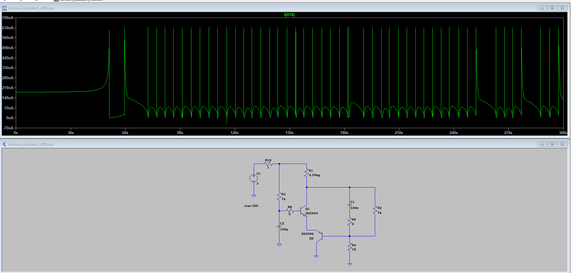
The good news is that by increasing the resistance and capacitance, I've confirmed it's possible to run the oscillator at 1 lux on the keychain solar cell:
If measured at the output pin of transistor Q2, it produces a 2 volt pulse every couple of seconds:
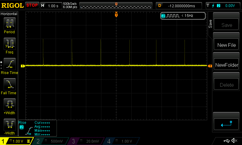
I'm pretty confident it will run at even lower lux, al beit producing a lower voltage, but I'm not yet setup to test at less than 1 lux yet.
Here is an approximation of the modified circuit and its current consumption:
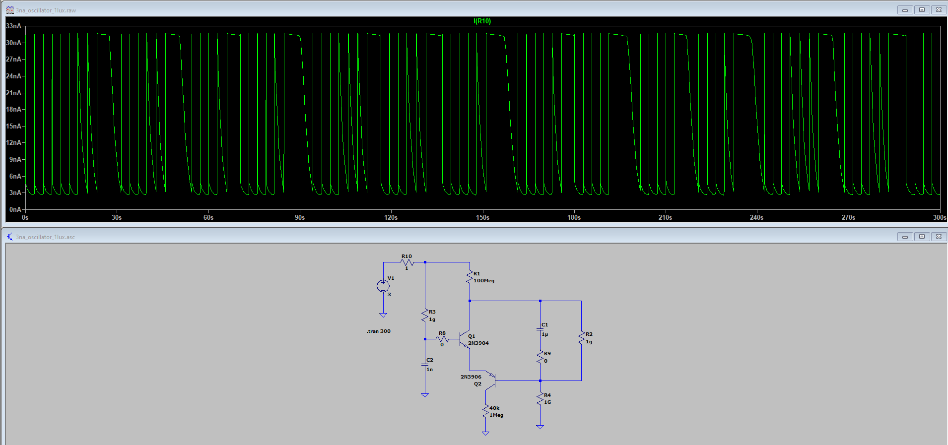
As you can see, both the average and the instantaneous current consumption are less than for TI's TLV5110 chip.And yes, I've confirmed through testing that it can self-start at 1 lux even if it had been pitch black prior! In that case it starts a pulse train at lower magnitude but higher frequency and gradually works it's way up to the 2 volt magnitude at the 0.5 Hz frequency, which at 1 lux is where it settles.
:smile: :smile: :smile: :smile: :smile:
-
@Mishka I've got good news, and I've got bad news. The bad news is that according to the LTSpice circuit simulator, the Dave Johnson circuit, as given, is nowhere near 3na of power consumption. It's much higher than that. Here's what it shows as the current passing through the R10 resistor in the figure below:
The good news is that by increasing the resistance and capacitance, I've confirmed it's possible to run the oscillator at 1 lux on the keychain solar cell:
If measured at the output pin of transistor Q2, it produces a 2 volt pulse every couple of seconds:
I'm pretty confident it will run at even lower lux, al beit producing a lower voltage, but I'm not yet setup to test at less than 1 lux yet.
Here is an approximation of the modified circuit and its current consumption:
As you can see, both the average and the instantaneous current consumption are less than for TI's TLV5110 chip.And yes, I've confirmed through testing that it can self-start at 1 lux even if it had been pitch black prior! In that case it starts a pulse train at lower magnitude but higher frequency and gradually works it's way up to the 2 volt magnitude at the 0.5 Hz frequency, which at 1 lux is where it settles.
:smile: :smile: :smile: :smile: :smile:
-
@Mishka The circuit is more stable and consistent than the 3v simulation would suggest. I'm now totally sold on the value of simulation, but it's a bit problematic when a solar cell/panel is involved because for an accurate simulation you need to find an accurate "equivalent circuit" to use in place of the cell/panel, and for accuracy that means a 5 element circuit: two diode, shunt resistor, series resistor, and a current source. However, figuring out the correct values for those parts requires a lot of measurements to get the desired accuracy and is a project in itself.
That said, I'm optimistic that there are some less mainstream transistors that will allow the circuit to run at lower voltage.
Hello! It looks like you're interested in this conversation, but you don't have an account yet.
Getting fed up of having to scroll through the same posts each visit? When you register for an account, you'll always come back to exactly where you were before, and choose to be notified of new replies (either via email, or push notification). You'll also be able to save bookmarks and upvote posts to show your appreciation to other community members.
With your input, this post could be even better 💗
Register Login