RFM69/95 won't run
-
Hi all,
I am trying to read the soil moisture and send it via radio. Therefore I bought a SX1278 radio chip but can't get it run.
It is connected to my 3.3V arduino pro mini like described in the documentation:
SX1278 ->  Arduino Pro Mini 3.3V

GND    ->  GND
VCC    ->  VCC
MISO   ->  MISO (D11)
MOSI   ->  MOSI (D12)
SLCK   ->  SCK (D13)
NSS    ->  SS (D10)
DIO0   ->  INT0 (D2)
Everytime I fire the arduino up, I see the following messages (debug activated):
208 MCO:BGN:INIT NODE,CP=RRNNA---,FQ=8,REL=255,VER=2.3.2
335 TSM:INIT
350 TSF:WUR:MS=0
419 !TSM:INIT:TSP FAIL
442 TSM:FAIL:CNT=1
462 TSM:FAIL:DIS
481 TSF:TDI:TSL
What does that mean and how can I fix it?
Thanks and regards!
Welcome to the MySensors community @cYnd !
The log parser is useful for interpreting the logs.
https://forum.mysensors.org/topic/666/debug-faq-and-how-ask-for-help/ shows them most common problems and how to troubleshoot them efficiently.
For init failed, the most common cause is a problem with the wiring. Triple-check the wiring. If you can't find any problem, post photos here and we'll try to spot what is wrong.
-
Hi mfalkvidd,
thanks for the welcome :upside_down_face:
You're right, I should use RFM95 and I changed it. However the same error:
208 MCO:BGN:INIT NODE,CP=RLNNA---,FQ=8,REL=255,VER=2.3.2
335 TSM:INIT
350 TSF:WUR:MS=0
378 !TSM:INIT:TSP FAIL
401 TSM:FAIL:CNT=1
421 TSM:FAIL:DIS
440 TSF:TDI:TSL
Also I tried the log parser earlier but it just tells me "Transport device initialization failed". I need to figure out why it can't initialize that device. I quadrouple-checked the wires and can't see any issues :unamused:
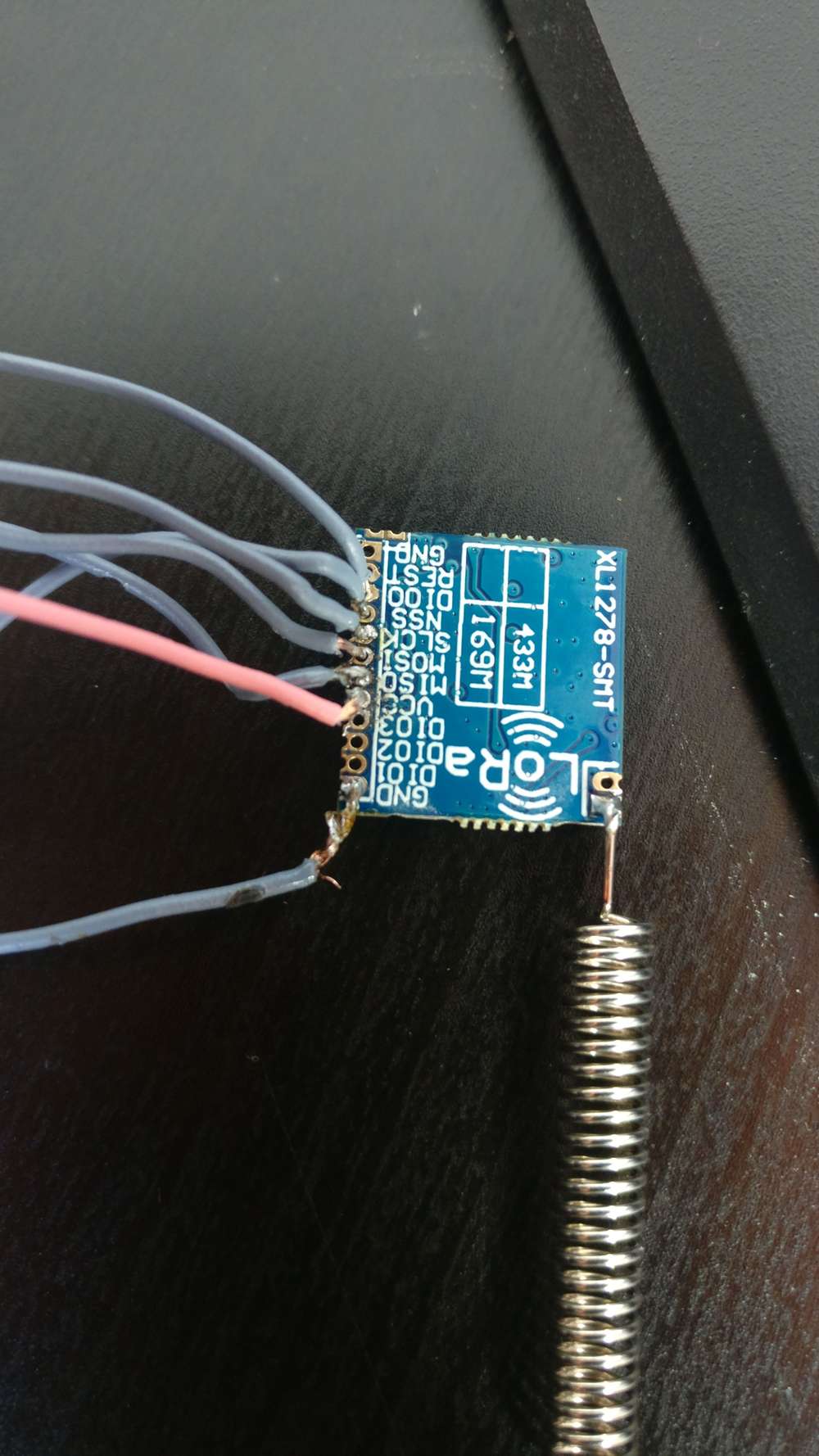
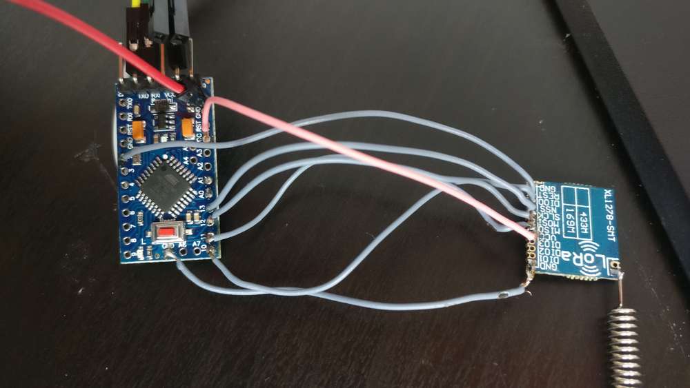
However here are some pcitures of it, maybe you find an issue? (Sorry, wiring is a bit messy :alien: )
-
@cYnd my guess would be insuffcient contact, or shorts between two or more pins. Learning to solder well takes some practice. You could use a multimeter to check if there are any shorts. Measuring good connectivity is trickier.
@mfalkvidd I tested shorts with my multimeter and didn't find any shorts. However I should receive next week some new of these chips and I will try to solder them new. Let's hope that that's the issue!
-
#define MY_RADIO_RFM95
#define MY_DEBUG_VERBOSE_RFM95
#define MY_RFM95_FREQUENCY (RFM95_434MHZ)
#define MY_RFM95_MODEM_CONFIGRUATION RFM95_BW125CR48SF4096
#define RFM95_RETRY_TIMEOUT_MS (3000ul)
#define MY_TRANSPORT_STATE_TIMEOUT_MS (3000ul)These are the defines I'm using. All done before including the MySensors.h.
What do you get if you try the above?
-
@niclas said in RFM69/95 won't run:
#define MY_RFM95_FREQUENCY (RFM95_434MHZ)
#define MY_RFM95_MODEM_CONFIGRUATION RFM95_BW125CR48SF4096
#define RFM95_RETRY_TIMEOUT_MS (3000ul)
#define MY_TRANSPORT_STATE_TIMEOUT_MS (3000ul)Hi Nicals,
thanks for the hints with the defines. Currently I am using this sketch:
#define MY_RADIO_RFM95
#define MY_DEBUG_VERBOSE_RFM95
#define MY_RFM95_FREQUENCY (RFM95_434MHZ)
#define MY_RFM95_MODEM_CONFIGRUATION RFM95_BW125CR48SF4096
#define RFM95_RETRY_TIMEOUT_MS (3000ul)
#define MY_TRANSPORT_STATE_TIMEOUT_MS (3000ul)
#define MY_BAUD_RATE 9600

#include <MySensors.h>
#define CHILD_ID 1

MyMessage msg(CHILD_ID, V_TRIPPED);

void setup() {

}

void presentation()
{
  present(CHILD_ID, S_MOISTURE);
}

void loop() {
  send(msg.set(12));
  sleep(10000);
}
So pretty basic I think. However I still get with your defines the error:
208 RFM95:INIT
292 RFM95:INIT:PIN,CS=10,IQP=2,IQN=0
342 RFM95:PTX:LEVEL=13
364 !RFM95:INIT:SANCHK FAIL
395 RFM95:RSL
Unfortunalety my replacement still didn't arrive (i guess due to the COVID-19 crisis....) so I can just work with the breakouts I got.
What exactly do you mean with:
@niclas said in RFM69/95 won't run:
And also:
The fourth line (configuration) needs to be the same on both the node and the gateway in order to work.
Be sure to set the frequncy to 434Mhz on both devices as well.I can't get is running on one devices (Pro Mini) due to the above mentioned errors, so I didn't even tried it with a second device. What exactly do you mean with fourth line? And which are the "both devices"?
@cYnd Hi! Sorry for really late answer. I must have missed the e-mail notification. Have you solved the issue yet?
I just read your first post and it says: MISO (D11), MOSI (D12). This is swapped according to for instance https://www.circuito.io/blog/arduino-uno-pinout/
MOSI->MOSI and MISO->MISO is correct but the pin number on the pro mini seems wrong?
-
Hey niclas,
no worries :-)
Got still no solution for this issue. On my first post I linked to the shop where i bought it and on the shops spec sheet, I find MOSI on D12. However on the official documentation I also find MOSI on D11. I switched these pins but still get the error:
208 RFM95:INIT
292 RFM95:INIT:PIN,CS=10,IQP=2,IQN=0
342 RFM95:PTX:LEVEL=13
364 !RFM95:INIT:SANCHK FAIL
395 RFM95:RSL
I also found this tool for testing LoRa devices. With MOSI on D12 I just got FF on all addresses but with the switched pins I got:
Reg    0  1  2  3  4  5  6  7  8  9  A  B  C  D  E  F
0x00  00 08 00 08 00 08 00 08 00 08 00 08 00 08 00 08
0x10  00 08 00 08 00 08 00 08 00 08 00 08 00 08 00 08
0x20  00 08 00 08 00 08 00 08 00 08 00 08 00 08 00 08
0x30  00 08 00 08 00 08 00 08 00 08 00 08 00 08 00 08
0x40  00 08 00 08 00 08 00 08 00 08 00 08 00 08 00 08
0x50  00 08 00 08 00 08 00 08 00 08 00 08 00 08 00 08
0x60  00 08 00 08 00 08 00 08 00 08 00 08 00 08 00 08
0x70  00 08 00 08 00 08 00 08 00 08 00 08 00 08 00 08
I don't know if it is a good sign that I see some other values with the test programm or not.
Still any ideas how to get this working? -
Hey niclas,
no worries :-)
Got still no solution for this issue. On my first post I linked to the shop where i bought it and on the shops spec sheet, I find MOSI on D12. However on the official documentation I also find MOSI on D11. I switched these pins but still get the error:
208 RFM95:INIT
292 RFM95:INIT:PIN,CS=10,IQP=2,IQN=0
342 RFM95:PTX:LEVEL=13
364 !RFM95:INIT:SANCHK FAIL
395 RFM95:RSL
I also found this tool for testing LoRa devices. With MOSI on D12 I just got FF on all addresses but with the switched pins I got:
Reg    0  1  2  3  4  5  6  7  8  9  A  B  C  D  E  F
0x00  00 08 00 08 00 08 00 08 00 08 00 08 00 08 00 08
0x10  00 08 00 08 00 08 00 08 00 08 00 08 00 08 00 08
0x20  00 08 00 08 00 08 00 08 00 08 00 08 00 08 00 08
0x30  00 08 00 08 00 08 00 08 00 08 00 08 00 08 00 08
0x40  00 08 00 08 00 08 00 08 00 08 00 08 00 08 00 08
0x50  00 08 00 08 00 08 00 08 00 08 00 08 00 08 00 08
0x60  00 08 00 08 00 08 00 08 00 08 00 08 00 08 00 08
0x70  00 08 00 08 00 08 00 08 00 08 00 08 00 08 00 08
I don't know if it is a good sign that I see some other values with the test programm or not.
Still any ideas how to get this working?@cYnd hmm.. too bad..
I guess I would start by downloading the Lora library by Sandeep Mistry in Arduino IDE and just run the example provided, I think one is called dump_registers. If that doesn't work I would start to suspect hardware failure or some problem with the wires.
And also, check that all the gnd pads of the module are connected to each other. I used a Bluetooth module once that needed all the gnd pins connected.
-
@cYnd hmm.. too bad..
I guess I would start by downloading the Lora library by Sandeep Mistry in Arduino IDE and just run the example provided, I think one is called dump_registers. If that doesn't work I would start to suspect hardware failure or some problem with the wires.
And also, check that all the gnd pads of the module are connected to each other. I used a Bluetooth module once that needed all the gnd pins connected.
-
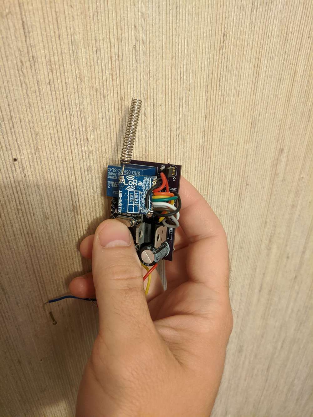
Found a picture of my node. I hooked up both the GND pads. Can't remember if it was necessary.
Still no luck with your module?
@niclas Still no luck when connection both grounds. Also measured them and they are both connected, even without soldering an cable to it.
I just ordered the RA AI02 modules so let's hope that these will arrive soon and will work (still didn't receive my replacements).A real pity that I can't get these to work :(
-
@niclas Still no luck when connection both grounds. Also measured them and they are both connected, even without soldering an cable to it.
I just ordered the RA AI02 modules so let's hope that these will arrive soon and will work (still didn't receive my replacements).A real pity that I can't get these to work :(
@cYnd Well I'm out of ideas. Could be a hardware issue, perhaps you shorted something when handling the module or you exposed it to 5V?
Is the VCC output from the Mini 5V or 3.3V? If you supply the mini board with 3.3V you should connect the module VCC to 'raw' if i remember correctly.
I use the RA-01 and RA-02 all the time so hopefully you will be very pleased with them. Good luck!
-
Looking at the images, the wires might not be properly connected, a few wires look like they're just plugged in. In that case even the slightest movement could cause issues.
@Avamander The cables are solder from the other side and I just took a picture of the side with the writing so you can trace if it's correctly wired.
-
@Avamander The cables are solder from the other side and I just took a picture of the side with the writing so you can trace if it's correctly wired.
Hello! It looks like you're interested in this conversation, but you don't have an account yet.
Getting fed up of having to scroll through the same posts each visit? When you register for an account, you'll always come back to exactly where you were before, and choose to be notified of new replies (either via email, or push notification). You'll also be able to save bookmarks and upvote posts to show your appreciation to other community members.
With your input, this post could be even better 💗
Register Login