Help needed to setup a RFM69 & ESP8266 Gateaway on Adafruit Feather Huzzah
-
Thank you @electrik
My intent is to use RFM69HW 868Mhz
I compared with photos on the internet like heremine is:
as far as i understand my reading my RSSI values seem to tell my signal is very weak and noisy ?
I tried to provide the pwr to the rfm69 with an external source instead of the esp8266 but i was not better. -
Thank you @electrik
My intent is to use RFM69HW 868Mhz
I compared with photos on the internet like heremine is:
as far as i understand my reading my RSSI values seem to tell my signal is very weak and noisy ?
I tried to provide the pwr to the rfm69 with an external source instead of the esp8266 but i was not better.@hlehoux Hi!
I had quite alot of trouble with NRF24 modules with shaky connections despite doing everything that has been discussed in forum with power supply etc and have ordered a bunch of RFM69's to hopefully improve this according to others in forum claiming better stability with RFM''s. Haven't tested yet but reading this is a bit dissapointing.
One thing though. Readings in log shows very high RSSI values and if it is measured in dBm this is very bad. The lower value the better I believe. Antenna issue ? -
Thank you @electrik
My intent is to use RFM69HW 868Mhz
I compared with photos on the internet like heremine is:
as far as i understand my reading my RSSI values seem to tell my signal is very weak and noisy ?
I tried to provide the pwr to the rfm69 with an external source instead of the esp8266 but i was not better.@hlehoux can you take a photo from the back also? There should be a table telling which one it is exactly.
@hakha4 said in Help needed to setup a RFM69 & ESP8266 Gateaway on Adafruit Feather Huzzah:
Antenna issue ?
You could be right.
What antenna do you have?
-
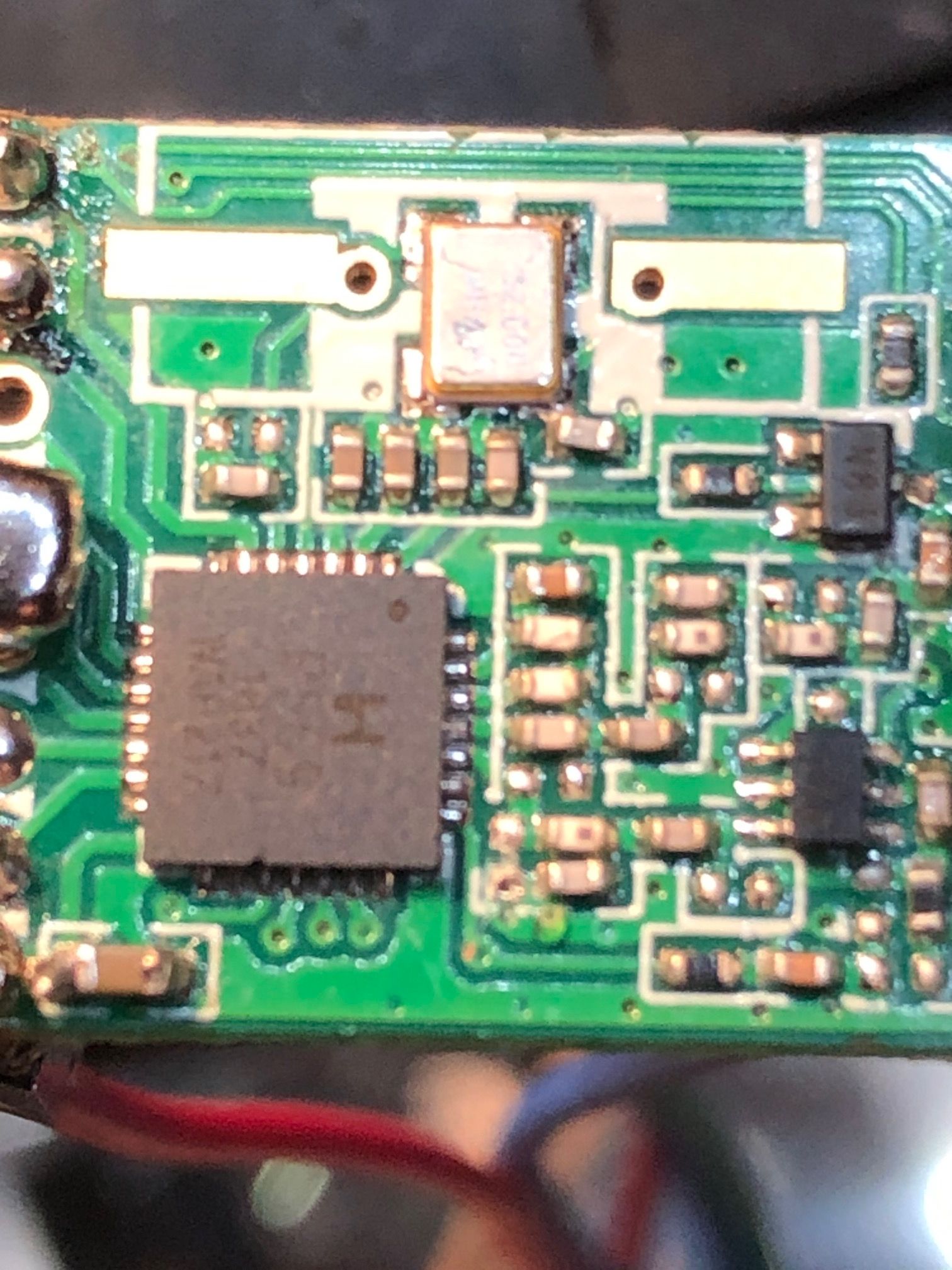
Hello, here are 2 photos
one from the back:
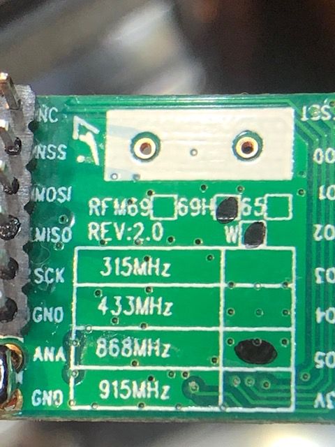
I'm not sure what the "W" means, i read chinese copy don't have it ?
one from the antenna:
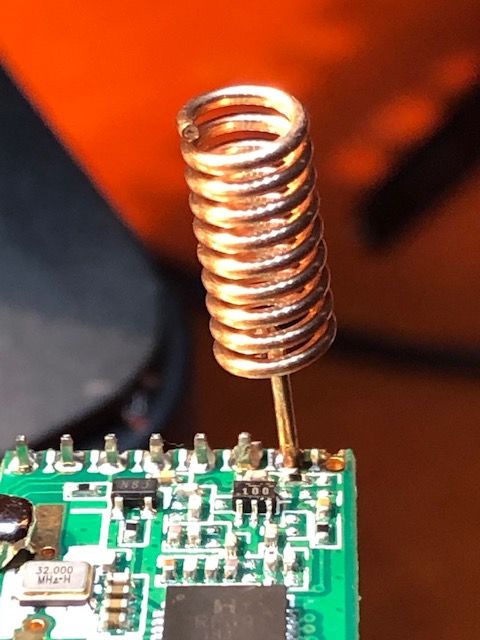
It should be the good size for 868 MHzI don't use "ground plane" or sort of, would this explain so bad RSSI ?
Thank you again for your help and patience
-
@hlehoux Hi!
I had quite alot of trouble with NRF24 modules with shaky connections despite doing everything that has been discussed in forum with power supply etc and have ordered a bunch of RFM69's to hopefully improve this according to others in forum claiming better stability with RFM''s. Haven't tested yet but reading this is a bit dissapointing.
One thing though. Readings in log shows very high RSSI values and if it is measured in dBm this is very bad. The lower value the better I believe. Antenna issue ?@hakha4 i also have several NRF24 nodes and gateaway
After trying several antenna/tranceiver, i recommend using
"E01-ML01DP5 Long Range SPI nRF24L01P 2.4Ghz 100mW SMA Antenna IoT Wireless Transceiver Transmitter Receiver nRF24L01P RF Module"as a repeater
It gives far better range resultsAnyway i wanted to try RFM69 to avoid having many repeaters
-
Hello, here are 2 photos
one from the back:
I'm not sure what the "W" means, i read chinese copy don't have it ?
one from the antenna:
It should be the good size for 868 MHzI don't use "ground plane" or sort of, would this explain so bad RSSI ?
Thank you again for your help and patience
@hlehoux Hi!
I'm not sure what the "W" means, i read chinese copy don't have it ?W means the low power output variant (+13dBm). There is another version named 'HW' which give a higher transmission output (+20 dBM). As elektik pointed out, check out the solder of the antenna. Did the antenna come presoldered or you did it yourself?
Another option for the coiled antenna is a straight copper wire (8,6 cm long) that gives better transmission according to many sources. Google! theres's alot information about this -
@hlehoux Hi!
I'm not sure what the "W" means, i read chinese copy don't have it ?W means the low power output variant (+13dBm). There is another version named 'HW' which give a higher transmission output (+20 dBM). As elektik pointed out, check out the solder of the antenna. Did the antenna come presoldered or you did it yourself?
Another option for the coiled antenna is a straight copper wire (8,6 cm long) that gives better transmission according to many sources. Google! theres's alot information about this@hakha4 said in Help needed to setup a RFM69 & ESP8266 Gateaway on Adafruit Feather Huzzah:
There is another version named 'HW' which give a higher transmission output (+20 dBM).
There is a black spot on the PCB after "69H" and after the "W" so this is the RFM69HW
-
Hello, here are 2 photos
one from the back:
I'm not sure what the "W" means, i read chinese copy don't have it ?
one from the antenna:
It should be the good size for 868 MHzI don't use "ground plane" or sort of, would this explain so bad RSSI ?
Thank you again for your help and patience
@hlehoux
unfortunately, lot of devboards have non-optimized gnd plane for RF, especially for subghz (small or splitted gnd plane by routes..).
Moreover, devboard+dupont cable+external rf module is not ideal.
With rfm69, you should get a nice range.
Though, why on one of your picture, antenna seems shorted to gnd??
Imho I would have chosen something else than esp8266 (esp32??) in your case, but your choice :)To check if this is related to your gnd plane and your build is ok, you could also try to hook two straight wires as a dipole antenna to your radio (one to ANA, the other to GND in opposite direction will replace a ground plane). Google for examples, it's simple to try
-
The modules correspond to what it should be.
It looks like your ground is connected to the ANT pin on the picture, on the bottom side of the PCB? -
@hlehoux
unfortunately, lot of devboards have non-optimized gnd plane for RF, especially for subghz (small or splitted gnd plane by routes..).
Moreover, devboard+dupont cable+external rf module is not ideal.
With rfm69, you should get a nice range.
Though, why on one of your picture, antenna seems shorted to gnd??
Imho I would have chosen something else than esp8266 (esp32??) in your case, but your choice :)To check if this is related to your gnd plane and your build is ok, you could also try to hook two straight wires as a dipole antenna to your radio (one to ANA, the other to GND in opposite direction will replace a ground plane). Google for examples, it's simple to try
@scalz Thank you very much!
Unfortunatly, the antenna seems shorted to ground only because this is the "head" of the pliers i used to take the photo.i use esp8266 because i received for free a lot of many adafruit huzzah feathers :-)
i will try your suggestion to hook two straight wires as a dipole antenna and report if this is better.
For sure my "development" setup is devboard+dupont cable+external rf and this should not be the final version ; anyway loosing 50% of messages with distance of 1 meter is disappointing.
-
try adding :
#define MY_RFM69_FREQUENCY RFM69_868MHZjust in case....
My first prototype using dupont cables and piece of wire as antenna gave me 500m range with 3 or 4 houses between me and gateway.
Try old driver, no RSSI reporting, but my whole network runs on old driver.@hlehoux 1m range is usually caused by radio type misconfiguration, like running HW radio as low power or other way round. Another possibility is faulty radio.
-
Strangely, i also have another bunch of RFM69s that are marked as H but not W. What does it mean ?
-
@scalz
Could you explain how to read these rssi reports, and how to adjust the configuration of the nodes so the reliability goes up?
I know there is a setting RFM69_TARGET_RSSI_DBM but it is not clear for me how to use this exactly.@electrik
in logs, RFM69:CSMA:RSSI=-104 is the noise floor
and RFM69_TARGET_RSSI_DBM define the rssi you want to have for your node.so if you have a noise floor of -100, you could adjust your target to -85 or less. But maybe you could get a few retries with -90 target.
rfm69 power level can be adjusted from -18 to +13db. 13db=100% power= 45mA power consumption.
for example, let's say your target is -70, and your power level has been autoadjusted to +5.
then if you set, the target to -80 or less, power level will decrease to maybe -8 or even less, it depends on your environment and your build.
And vice versa, if you set target to -50, ATC will set a higher power level.ATC is used to auto-adjust radio power level consumption for battery nodes, so they use only energy they need. This also make your rf environment "greener". No nodes sending loud messages if not needed.
Another example, I recently designed a new node. Noise floor here is around -98db.
With a target of -70 if I remember, power level was autoadjusted to +5db.
After adjusting target to -87db, power level has decreased to -11db, which equals to 20% power.
And there are no NACK nor retries.
So this node now requires less energy for sending messages and that will save battery.
This is for an indoor node, 10m distance with 2 brick walls obstacles.old driver doesn't have ATC management. I've no problem so far with new driver.
I guess H would mean High power version. But to be sure, yuo just have to google for rfm69 pics and you'll see which version you have. Existing versions are : RFM69HW, RFM69W, RFM69HCW, RFM69CW
-
@electrik
in logs, RFM69:CSMA:RSSI=-104 is the noise floor
and RFM69_TARGET_RSSI_DBM define the rssi you want to have for your node.so if you have a noise floor of -100, you could adjust your target to -85 or less. But maybe you could get a few retries with -90 target.
rfm69 power level can be adjusted from -18 to +13db. 13db=100% power= 45mA power consumption.
for example, let's say your target is -70, and your power level has been autoadjusted to +5.
then if you set, the target to -80 or less, power level will decrease to maybe -8 or even less, it depends on your environment and your build.
And vice versa, if you set target to -50, ATC will set a higher power level.ATC is used to auto-adjust radio power level consumption for battery nodes, so they use only energy they need. This also make your rf environment "greener". No nodes sending loud messages if not needed.
Another example, I recently designed a new node. Noise floor here is around -98db.
With a target of -70 if I remember, power level was autoadjusted to +5db.
After adjusting target to -87db, power level has decreased to -11db, which equals to 20% power.
And there are no NACK nor retries.
So this node now requires less energy for sending messages and that will save battery.
This is for an indoor node, 10m distance with 2 brick walls obstacles.old driver doesn't have ATC management. I've no problem so far with new driver.
I guess H would mean High power version. But to be sure, yuo just have to google for rfm69 pics and you'll see which version you have. Existing versions are : RFM69HW, RFM69W, RFM69HCW, RFM69CW
@scalz great explanation of new driver functionality.
Some cheapest Aliexpress boards are not marked at all or marked with Frequency only. H versions have additional sot23-6 chip near antenna pin.Wonder why the new driver wasn't stable enough to do 12kB OTA firmware update even once, regardless of settings :thinking_face: . Same GW and node works flawlessly on old driver over 10-100 meters.
-
@scalz great explanation of new driver functionality.
Some cheapest Aliexpress boards are not marked at all or marked with Frequency only. H versions have additional sot23-6 chip near antenna pin.Wonder why the new driver wasn't stable enough to do 12kB OTA firmware update even once, regardless of settings :thinking_face: . Same GW and node works flawlessly on old driver over 10-100 meters.
@Sasquatch
yes rfm modules are nice for long range.
ok. we will re-test OTA+new driver on my new board soon, and will keep you updatedI agree seems OP has setup problem, could be
- H vs non-H define
- IRQ is not triggering for receiving msg
- weak GND counterpoise for antenna,
- power supply. For power I usually use 100uf+0.1uf close to the module. 100uf when it's batt powered (for coincell, I like to have two big capa+0.1uf), else it's possible to use a smaller value like 33-47uf
-
@scalz I do agree,
I found that even USB powered NodeMCU gateway needed at least 10uf ceramic or 47uF electrolytic capacitor on radio supply, without it heavy traffic was causing gateway freezes and reboots. There is 100nF capacotor on rfm69 and 220nf on RFM69H modules(at least my Aliexpress cheap clones have them) right next to the VCC pin, so i skip the external one.
Hello! It looks like you're interested in this conversation, but you don't have an account yet.
Getting fed up of having to scroll through the same posts each visit? When you register for an account, you'll always come back to exactly where you were before, and choose to be notified of new replies (either via email, or push notification). You'll also be able to save bookmarks and upvote posts to show your appreciation to other community members.
With your input, this post could be even better 💗
Register Login