CNC PCB milling


  • Hero Member

    I upgraded to the brushless motor after 3D printing cottingbear's adapter. Then I ran @executivul 's test scripts to check its performance. It looks as though the new spindel can support faster feedrates, but the trace isolation is 0.7mm, which is much larger than the original cheapo spindle. 😞 It has an ER8 on it, not an ER11. Not sure if that's to blame (?). I wouldn't think so, though, because I'm using a 1.75mm collet on it.

    The z-axis still has a lot of flex in it. I think that's probably a factor. I'm not sure what can be done to mod my way out of that. Perhaps I'd be better off getting a proper CNC mill rather than this wobbly type of design.

    0_1526294001999_TESTS.jpg
    0_1526294333804_upgraded_spindel.jpg

    I can now see the advantage of having two z-axis motors, one on each side of the spindle. That would probably give it at least a bit more rigidity. Either that, or a single very rigid,, unmoving central column as used by mills.


  • Hero Member

    Any suggestions on how to improve it?


  • @neverdie said in CNC PCB milling:

    I can now see the advantage of having two z-axis motors, one on each side of the spindle.

    Maybe just a stronger stepper motor.


  • Hero Member

    I switched to a 52mm spindle, and now I'm getting better results:
    0_1526315694283_52mm_spindle.jpg
    0_1526315708643_52mm_results.jpg
    The benchmarks on the right were produced by the 52mm spindle. 🙂 Those on the left by the 54mm brushless spindle.


  • @neverdie I guess some backlash being present. Is the brushless heavier than the other one?
    The width of the cut is proportional to engraving bit tip size, depth of cut, tip angle, the spindle itself should be irrelevant except runout, of course, but you will hear the runout long before you see it, a 0.1mm of runout will make a hell lot of noise and rattling.
    For greater rpms er8 is better than er11, my 60k rpm has er8 the 24k have er11.
    Try to find the highers resonance pole rpm, turn the rpm to max, slowly decrease it while listening carefully, take a note when it's quieter, use the highest rpm that runs quietly. This setting unfortunately changes with every tool change, sometimes you won't have a good enough rpm resonant pole so you take out the bit, nut and collet and reassemble. By turning them you change the invisible runout a bit and you get another system state. On my spindle every 1/10-1/15 tool changes results in heavy resonance and I must proceed as above.


  • Hero Member

    @executivul Cool! Here's my first attempt at that, and it's already producing a visibly different result:
    0_1526341437544_reduced_resonance.jpg

    As to which spindle is heavier, I don't know. The next time I demount the brush spindle, I'll weigh it and let you know.

    Thanks!


  • Hero Member

    This guy developed his own method for balancing the high speed motors used on his quadcopter. I can't help but think that maybe something similar could be done on a CNC spindle.
    In depth video how to balance brushless motors using a vibration meter and tape - Ontaerial – 25:35
    — Yuri Retro


  • Hero Member

    And these guys have the same idea, but they instead use a laser to visualize the magnitude of the vibration:
    Flite Test - Laser Balancing Props - FLITE TIP – 07:11
    — FliteTest


  • @neverdie knowing the vfd has a speed input I guess I could wire a simple arduino with a mic. Take note of the sound level and get it calibtared in no time, at the push of a button, but that project is far away, I have other things on my mind for the next few months.


  • hello everyone,

    what is the current status with the quality, fine traces and result stability?
    after a long absence I finally had some time to finish my new board and prototype it.
    I don't have those issues that appearing for some of you, the result is pretty nice, the milling quality is the same across the whole board.
    in this design the thinnest traces were 15mils, and the smallest vias were 0.8mm with 0.3mm drilled holes.

    0_1527023946011_small_20180521_092313.jpg

    1_1527023946013_small_20180521_101938.jpg

    2_1527023946014_small_20180521_102134.jpg

    3_1527023946014_small_20180521_124252.jpg

    just for reference, please see my relevant configuration options detailed below:

    tools

    • cnc: cnc2418
    • carving: 2001 bit (20 degree, 0.1mm end)
    • mounting holes and outline milling: 0.8mm endmill

    config

    • isolation routing: tool dia: 0.1176326981mm; width (# passes): 2; pass overlap: 0.05mm; cut-z: -0.05mm; feed rate: 200
    • milling: tool dia: 0.8mm; cut-z: -1.75mm; feed rate: 170; depth / pass: 0.3mm
    • drilling: feed rate: 120

    software:

    • flatcam
    • bcnc (also for the autoleveling)

  • Hero Member

    Hi Andrew,

    Since you ask about status, here's mine: I've now replaced all the aluminum smooth rods that came with my 2418 kit with chromed hardened steel ones which, it turned out, had about 0.04mm larger diameter. The result has been much less apparent vibration. I also upgraded the spindle to a higher rpm motor. I don't as yet have any quantified numbers to know whether the combination of doing all that has made any tangible improvement or not.


  • Hero Member

    @andrew I ran @executivul 's diagnostic with my new setup:
    0_1527093991402_trace_width.jpg
    Starting with 0.1mm, the trace width's increase by 0.1mm in each block.

    @executivul's g-code specified the feedrate at 1400.

    So, yeah, 15mil looks like it would be achievable, even at that faster feedrate. On the otherhand, the woodpecker setting limits x and y to 200mm speeds, so I guess (?) the speed never actually gets beyond those limits anyway.

    The next upgrade after this will be switching over to trinamic drivers, which may (?) be able to drive things a bit faster. That will likely require dropping woodpecker and switching over to marlin firmware so as to get the most out of the trinamic drivers.


  • @neverdie what was the cost for the overall upgrade?

    for me the 10 mil traces also worked with the default sw/hw configuration.

    did you change any parameter in the grbl firmware? 1400 feedrate is very nice, much faster than mine, however I did not use higher rates than 200 so far.

    your steppers are still the same? is it ok for the high feedrate without any issue?


  • Hero Member

    @neverdie said in CNC PCB milling:
    On the otherhand, the woodpecker setting limits x and y to 200mm speeds, so I guess (?) the speed never actually gets beyond those limits anyway.


  • @neverdie the controller does not limit it, but the firmware settings. however, based on my default settings the feedrate is limited (by config) to 800. check your $110, $111, and $112 config options.
    https://github.com/gnea/grbl/wiki/Grbl-v1.1-Configuration#110-111-and-112--xyz-max-rate-mmmin

    you are free to override this configuration with a different value, so you can try 1400 in the grbl firmware settings, which will cause real 1400 feed rate in case of you test G code.
    the questions is that how the steppers/spindle could handle this.


  • Hero Member

    @andrew said in CNC PCB milling:

    what was the cost for the overall upgrade?

    The spindle I'm currently using cost $34:
    https://www.aliexpress.com/item/BEST-300W-Mini-Spindle-motor-DC12-48V-ER11-12000rpm-Engraving-milling-grind-air-cooling-spindle-motor/32799767627.html?spm=a2g0s.9042311.0.0.27424c4dQrDJU8

    I power it with a separate, adjustable power supply, since it can go to 48v.

    I had to 3D print an adapter for the new spindle to fit onto the 2418. Cottingbear has one on thingiverse. Aside from the plastic filament needed for the print (maybe $2 worth), it requires just 4 short linear bearings and a lead nut.

    The 6 chromed steel smooth rods cost around $20-30 in total, including e-packet delivery.

    My feeling is that the steel rods are a worthwhile and very easy upgrade, even though I don't have data to prove they make any difference. Not sure yet whether the new spindle will eventually produce better results or not, although it does run quieter, which is nice. 🙂

    The yet to be used trinamic drivers cost $42.50: https://www.aliexpress.com/item/5X-MKS-TMC2130-V1-1-For-SPI-Function-Stepstick-Stepper-Motor-Driver-With-Heat-Sink-5PCS/32850180071.html?spm=a2g0s.9042311.0.0.27424c4ddQiQqN
    I got a couple extra in case I accidentally burn one or two of them out. I'll be plugging them into a RAMPS board, which is cheap, and which, as an arduino Mega 2560 shield, will replace the woodpecker board.


  • @neverdie Can you run a stock GRBL build on RAMPS?


  • Hero Member

    @dbemowsk said in CNC PCB milling:

    @neverdie Can you run a stock GRBL build on RAMPS?

    I don't know. I'm planning to use Marlin, which supposedly can exploit at least some of the TMC2130 driver's special features.

    After I get all that working, then I may upgrade to higher torque stepper drivers, still NEMA 17 though, as the trinamics can support more current than the A4988's that are on the woodpecker.


  • Hero Member

    I found out that I can buy precision rods and matching linear bearings directly from https://us.misumi-ec.com. Because of the tighter fit, this would, I'm guessing, reduce the deflection on the x-axis.


  • By checking this discussion i have found a project online called: pcb cyclone factory. I am novice. What do you think about it ?
    https://reprap.org/wiki/Cyclone_PCB_Factory


  • Hero Member

    @jeremushka Looks like it might be kinda shakey. Vibration is a notable enemy.


  • Hero Member

    Looks no worse than what I have .


  • I would like to create pcb's with a 0.5mm pitch as a target and I have tried to follow this thread for hints. Have you @andrew, @NeverDie or @executivul been able to get that done with the milling method?

    Then one of the problems with the 2418 that @NeverDie seemed to have was that the machine itself was not stable enough. Do you think that the cheap 3018 work better? For example

    https://www.aliexpress.com/store/product/CNC-3018-laser-options-with-ER11-diy-cnc-engraving-machine-Pcb-Milling-Machine-Wood-Carving-machine/424291_32806004900.html
    or
    https://www.amazon.com/Control-Machine-Engraver-Controller-Extension/dp/B07KYH6BTK/ref=sr_1_6?ie=UTF8&qid=1548751586&sr=8-6&keywords=cnc+3018


  • @lamikr pls see one of my very first test I made after I built my cnc. check the TQFP100 footprint.

    for me, the cnc2418 was good choice. with proper assembly it is very stable and its output is stable.
    I was using the cnc for designs down to 10mil traces without any issue.

    so, I have good experience with my low cost cnc but do to the lack of hands-on experience with other devices, I cannot compare or recommend others.

    0_1548754957612_small_20171101_210626.jpg

    1_1548755165291_small_20171119_164624.jpg

    0_1548755165290_small_20171119_163603.jpg


  • Hi everyone,

    can someone help me pick out what to order from amazon.de?

    I would like to order a 3018 pro, but which one?

    What drilling bits would I need to order to mill PCB?

    Any help much appreciated!!


  • Hardware Contributor

    @dennisc - I think its a matter of taste and preference, but there is 728 posts in this thread, many describing the pro and cons with different drillbits and mashines. Since its DIY its very hard to tell exactly what to pick - atleast for me - but lets see if someone else is bolder.


  • @sundberg84

    I know there are so many posts!

    I am under a bit of time pressure and can't wait for aliexpress or bang good, so I was hoping somebody just ordered something off amazon. (and I could copy that).

    I am interested in the 3018 Pro, that on looks good enough price wise at least. But maybe had an experience with Sainsmart or something else.

    Other important reason is that there have not been many posts in the last months in this thread.


  • I have bought a 3018 Pro and put it together today.

    I'm now trying to find out how to calibrate it, any tips would be awesome!

    Im using GBRL control.

    thanks!


  • Ok calibration was quite easy.

    I managed to get the x, y and z axis zeroed. Only thing I am wondering is this:

    I can see my file goes 0.2 mm deep. Is there a button to alter the offset?

    I found I had to do all kind of fake zeroing to get it deeper!


  • @dennisc I have myself ordered the 2418 from the Jack's store.
    I also ordered the parts for Ant's team's PCB machine based on the BOM on
    https://bitbucket.org/compactpcbmaker/cpcbm/src/master

    It will be intersted in for comparing these two and I think money will not be wasted as other one could in the end anyway be used for drilling if other one does the route milling.

    Another thing I am wondering how this will compare to Eleksmaker A3 with 405nm laser and Marco Reps modifications.
    Important upgrades for the EleksMaker PCB laser CNC machine – 07:40
    — Marco Reps

    Laser is interesting due to it's accuracy but I am worried from the reflected beams. I have only found out so classes for protecting from the beam but would rather like to see a full box made from proper shielding material on top of the Eleksmaker.

    Fourths interesting thing is the openpnp based pasta dispenser and pick and place machine.
    https://hackaday.io/project/165743-foxbuild-pnp
    https://mcuoneclipse.com/2018/06/26/building-a-diy-smt-pickplace-machine-with-openpnp/


  • @lamikr said in CNC PCB milling:

    Laser is interesting due to it's accuracy but I am worried from the reflected beams. I have only found out so classes for protecting from the beam but would rather like to see a full box made from proper shielding material on top of the Eleksmaker.

    Fourths interesting thing is the openpnp based pasta dispenser and pick and place machine.
    https://hackaday.io/project/165743-foxbuild-pnp
    https://mcuoneclipse.com/2018/06/26/building-a-diy-smt-pickplace-machine-with-openpnp/

    I made an enclosure for my 3D printer in which I had a plexiglass panel for the door. Not long ago I made a mod for my 3D printer that allows me to change to different tool heads. https://www.thingiverse.com/thing:3407486

    One of the tools is a 6 watt laser module. I got a piece of this to replace the plexiglass on the door of my enclosure. It is rated for the wavelength of my laser module which is 450nm. https://jtechphotonics.com/?product=445nm-laser-shielding This might be a bit small if you wanted to make a complete cover made out of this stuff though.


  • @dbemowsk Thanks for the shielding material tip, I may buy it later if starting to work with 0.5w 405nm laser for engraving. (Some safe enclosure definetly needed)

    In the meantime I have not constructed my CNC 2418 from Jack's store and tested that I can control it by seding the g-gode commands from terminal. I have not yet tried to workflow from Kicad, to flatcam and from there to bCNC.

    Original GRBL firmware was 0.9j but I managed to upgrade it to v1.1h over USP without need for using another arduino as a ISP programmer and wiring it to woodpecker. Arduino-ide did not detect the board automatically but the flashing to grbl 1.1h worked with a following command out of the box on my linux by using a following avrdude command:

    avrdude -v -C/etc/avrdude/avrdude.conf -pm328p -carduino -P /dev/ttyUSB0 -D -Uflash:w:grbl_v1.1h.20190825.hex
    

    This thread is so long that it takes lot of time to try to find all important steps. But what I have gathered is that 3 most important things that I am still missing before trying to mill are the

    1. auto leveling
      What I read, this should be easy with gBNC. Mostly connect one wire from the drilling bit to A5 pin in woodpecker and another from woodpecker's ground to pcb.

    2. Current adjustment for all three A4988 motors.
      If I understood correctly @andrew and @NeverDie both changed that from 0.6A to 0.9A? Can that be done only by rotating the potentiometer on a4988 driver boards or do I also need to add some resistors?

    3. End stops modules? Could them be connected somehow to woodpecker?


  • Hero Member

    Looks like the price on more precise equipment has come down:
    https://www.aliexpress.com/item/32889386703.html?spm=a2g0o.detail.1000014.25.50f15e323iLiE4&gps-id=pcDetailBottomMoreOtherSeller&scm=1007.13338.141931.0&scm_id=1007.13338.141931.0&scm-url=1007.13338.141931.0&pvid=6d201006-5b15-41db-bc2e-2f9421010139

    Either this or a more classic mill setup is probably the most cost effective for cutting pcbs more accurately. It's the twisting slop that most limits my current CNC's PCB fidelity.


  • Hero Member

    On my previous attempts, I wasn't aware there existed any options for milling PCB's beyond just v-bits. Now it seems that there's quite a range of actual end-mill bits in diameters as narrow as 0.05mm!

    Milling PCB tracks on a Tormach with a "Very" Small End Mill – 00:53
    — CNCTurboStep

    They look like this:
    alt text

    From what I've read, when using end mills with less than 100 micron cutting diameters, it's recommended to do step cutting, due to the delicate nature of the bit. That's fine with me: once I set up the machine with a PCB blank, I can walk away and come back when it's done.

    Anyone tried using end mill bits like these for milling PCB's, and if so, how do they compare?


  • @NeverDie I've got this one several months ago, I couldn't say it's a good one though.
    here is the list of drawbacks I've had/have:

    • spindle fixed speed 12000RPM. I added automatic circuit breaker to it so it won't put home on fire when it rams into the table. (threw away DC connector on top as it wasn't reliably holding both sides to begin with and then it was burned a bit after spindle stall). Runout is about 50um. + whatever collet would add (cheapest ones from aliexpress were disappointment in a range 50~100um, so I've got precision one locally)
      The only thing I'm going to invest into this machine is 24K spindle + vfd with small runout. (it just arrived but still unpacked, it will need adapter plate to mount it on Z plate, hopefully I'll make something with adjustable tilt to simplify tramming)
    • it was poor assembled, one has to disassemble and put it back properly tightening screws and making sure belts are not loose (that solved lost steps issue)
    • it uses lead screws with bronze nuts like in 3D printers and a plastic spacer between nuts (to counter backlash).
    • axis plates are attached to nuts via that same plastic spacer (not sure how it would do with milling aluminium)
    • there was (still is) some backlash (~40-60um) left after tightening nuts,
      one could tighten it further but that would come at cost of lower speeds as no-name steppers start stalling (currently I have 2300mm/min max on XY plane, and one would wish for more rapids if one would wish to try milling plastics)
    • squaring it is nightmare, basically the only option you have is adjusting X pillars and try to square XY and YZ at the same time (and there isn't much space to play with it). For tramming spindle on XZ plane, I had to move up one side of X support plate as there isn't sufficient play in spindle mount and then level sacrificial board to make X axis square to the table.
      As result of several iterations, I've got ±40um difference in hight across the table. XY axises still not square ~0.5mm on opposite sides of of the table on X axis, but I don't have heart to repeat whole procedure again (yet).
    • controller dial is way too sensitive, so I practically don't use it at all. Ribbon cable to SD card fell appart, USB connector for PC doesn't work reliably (but mostly works if you got it in working position).

    The whole setup was bought to prototype PCBs and later on learn how to mill other stuff (plastics/aluminium) for casing prototypes.

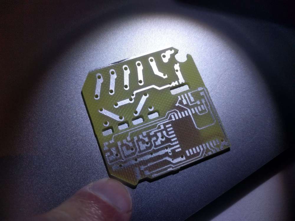
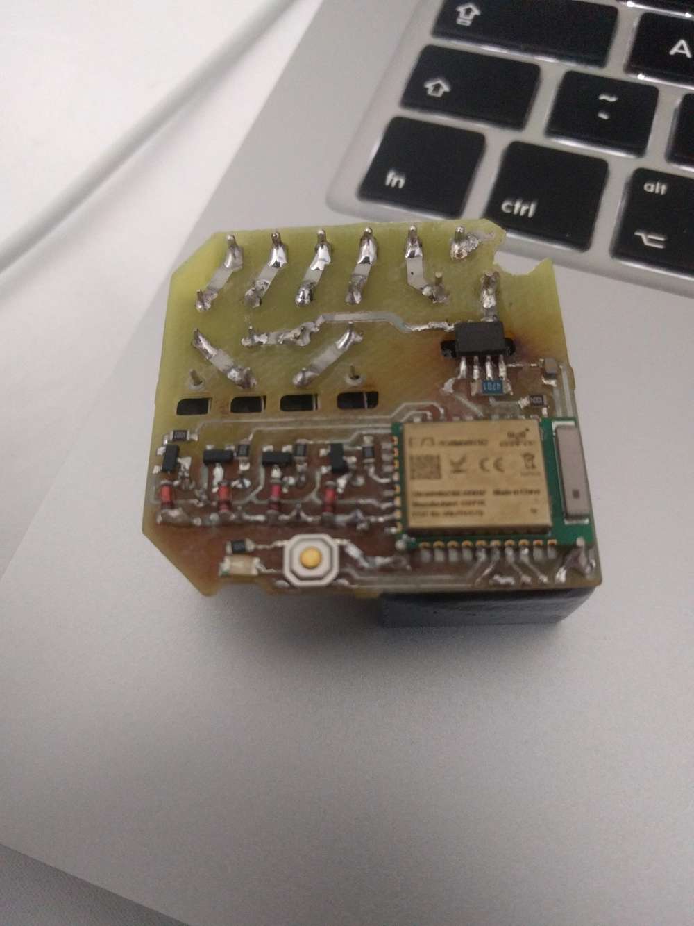
    So far I've managed to mill reliably 0.3mm isolation paths with 60*0.2 engraving bit (but as you did, I've redesigned board with wider traces to reduce failure chances). In Flatcam, I had to add runout value to tip diameter to avoid track thinning. Perhaps I could do more fine traces now (after all the tuning) with more fragile 30 or 15 degree bits, but I won't try till I get current project out of the door (at least hardware part of it).
    IMG_20200405_213028.jpg
    IMG_20200407_134926.jpg
    IMG_20200407_134935.jpg
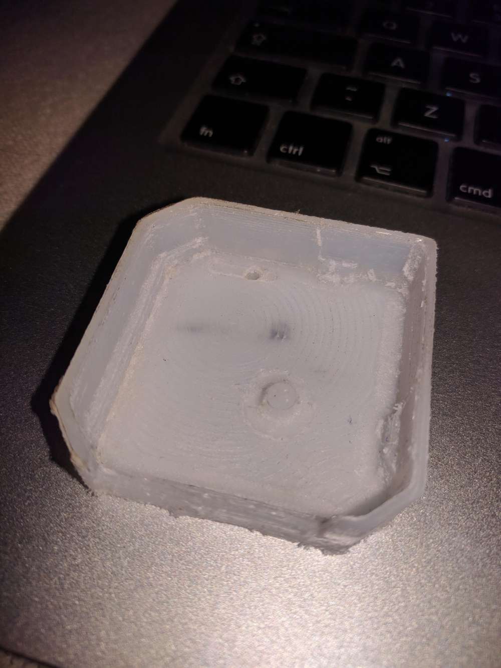
    and here is my 1st attempt to mill the case part
    IMG_20200417_162631.jpg


  • Hero Member

    I received one of the 0.2mm end mill bits, so I'll be having a run at it with that sometime soon. To give it the best chance, I plan to bed level with some large diameter endmills first, as I haven't tried that before and maybe it will help. Looking forward to it.

    Wegster has a series of impressive videos on youtube that are an inspiration that this is actually possible to do with fairly ordinary looking equipment (though they charge a small fortune for theirs):
    Double layer PCB prototyping 0.1 mm traces/spaces – 12:45
    — WEGSTR CNC

    Maybe there's more to it than meets the eye? Makes me wonder what exactly they're doing in order to accomplish it so perfectly.

    An alternative might be to connect a sharpie type pen and plot that way as a prelude to chemical etching. I haven't wanted to do that, but it's a fallback that might work to get fine pitch etches.

    Hackaday did a very insightful analysis of "the mother mill" which explained why it is surprisingly good at milling PCBs despite it's having a largely plastic frame construction:
    https://hackaday.com/2016/08/02/the-othermill-vs-import-a-technical-comparison/
    Usually success begets knock-offs, but I can't say that I've noticed any knockoffs of the OtherMill.

    I'd really like to have a machine with an automatic tool changer, where I could just launch it and come back when it's totally done with everything. I'm surprised that capability hasn't yet become more widespread.


  • Hero Member

    Anyone else out there using CNC to make their own PCB's? After taking a break from it for a while, I'm going to take another stab at it, now with the benefit of fresh eyes. Right off the bat I'm making a few changes:

    1. Flattening a space for the PCB on the sacrificial board so that little to no bed leveling will be required:
      upgrades.JPG
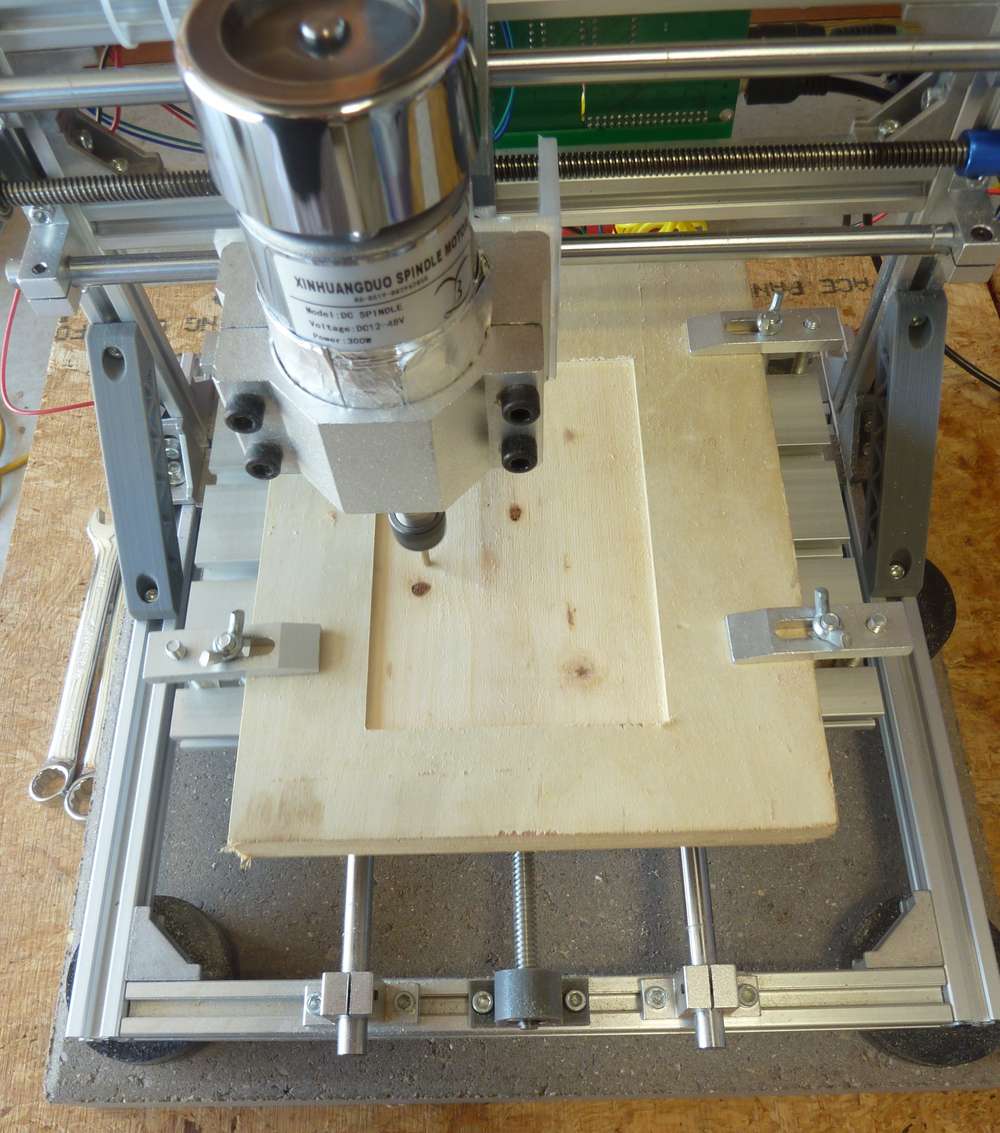
    2. As seen in the photo just above, using a concrete paver to stabilize the platform. This is a common tactic used in 3D printers.
    3. Mounting the printer on non-skid pucks (also shown in the photo) to guarantee that the CNC doesn't slide around.
    4. Using FR-1 instead of FR-4 as the substrate for the copper clad PCB.
    5. As already mentioned in the post just above, using end-mill bits instead of v-bits to accomplish the etching.
    6. Oh, and yes, I replaced the spindle I was previously using with this upgraded, more powerful spindle.
    7. Using a stronger double-sided tape ("Nitto Tape") to hold the PCB in position while the PCB is being etched by the CNC. Actually, I'm not unsure as to whether it's stronger than the double sided golf grip tape I was using previously, but I'm trying it today, so I'll soon have a basis on which to gauge it.
    8. Laying around somewhere I have some TMC drivers, and when I find them I'll use them to upgrade the rudimentary GRBL controller that came with the original CNC kit. Not sure if it will yield any improvements, but, meh, seems like it's worth trying.
    9. I've switched to a domestic fabricator of blank PCBs that I'll use instead of the Aliexpress ones. I don't know whether it will make a difference, but the quality does seem to be higher, and I can get them with thicker substrates than what I can find on aliexpress.
    10. I switched to a metal spindle mount.

    I've already noticed one anomaly that I hadn't noticed previously, which is that if I use Flatcam to set the depth of cut to 1.5875mm (equals 1/16 of an inch), then if I do it in 4 passes (where the first pass is at 0.5mm depth, the second at 1.0mm depth, the third at 1.5mm depth, and finally the last pass at 1.5875mm, I end up getting a shallower depth of cut than if I were to later do a depth of cut of 1.5875mm in just one pass. Not sure if this is caused by an error in chillipepr, the gerbal controller, or the stepper missing steps.

    Meanwhile, software seems to have improved since the last time I was using it, so I'm looking forward to trying it again as well as new alternatives. Anyone here have any favorites?


  • Hero Member

    I wasn't getting a completely smooth flattened area using just a 1/8" end mill, so I'm going to hazard a try with https://www.amazon.com/gp/product/B0000225VS/ref=ppx_yo_dt_b_asin_title_o00_s00?ie=UTF8&psc=1
    by switching to a 1/4" collet in my ER11 spindle.


  • Hero Member

    SOLVED: up until now I was running the "stable" release of FlatCAM, but it turned out to be so full of shortcomings that I decided to throw caution to the wind and install the latest beta release instead. I'm glad I did. Not only did it fix a range of problems that the stable release had, but it also has a "finishing" setting that's doing a much better job of smoothing out my spoilboard using a mere garden variety 1/8" end mill. 🙂 The main downside is that the "finishing" algorithm can take quite a while to run, so for speed's sake I'll still give the Freund a try. Freund cutting tools are pretty good quality, so I expect it will be an improvement.


  • Hero Member

    @niallain As far as v-bits go, I've lately had good results with this type:
    https://www.amazon.com/gp/product/B019K4OMBE/ref=ppx_yo_dt_b_search_asin_title?ie=UTF8&psc=1

    It's not as fragile as the typical aliexpress style v-bits.


  • Hero Member

    It's now possible to use an inexpensive open source controller to achieve both closed loop control and 0.02 degree resolution on a nema 17 stepper: https://hackaday.io/project/11224-mechaduino

    I get the impression the original maker isn't selling it anymore. So, you can make it yourself from the files posted or github, or a number of inexpensive clones are also available on aliexpress for around $15. By use of a magnetic encoder, it basically immediately corrects for any missed steps. In the case of 3D printing, that means no layer shifts, even if, as demonstrated in this youtube video, you were to whack the printhead hard with a rubber mallet during a print:

    S42B closed loop stepper motors - No more layer shifts! – 14:46
    — Teaching Tech

    As for CNC, it's a new level of control assuredness.

    Also, because the drivers offer a way to directly monitor how hard the servos are working, they should provide a way to make better informed decisions about increasing speed, acceleration, etc.

    UStepper appears to be another board that was conceived along similar lines.

    I'm planning to upgrade my nema 17's to ones with 3x the torque, and then later upgrade those upgrades with mechaduino/ustepper closed loop controllers. By sticking with nema 17, all these should be drop-in replacements for what's already there. i.e. no need to change couplers or other fittings.

    For even greater torque and precision I could outfit the steppers with planetary gearboxes, but, meh, I'll evaluate that after the upgrades already pending are completed. I presume they come with a downside of much slower speed.

    Anyone here done any of this? How did it go?


  • @NeverDie I recently finally made my first reliable PCBs, combining milling and laser. Both on the same Chinese build 3018. I enhanced my 3018 with a 7W laser diode a year ago. Selection of which one is the active device is done by a manual switch. Maybe some of my experiences are usefull to you or anyone else here.

    For milling I nowadays completely rely on the heightmap of Candle (GRBL1.1 on a WoodPecker board, not the original board of the machine), the Gcodes generated by FlatCAM which are in turn based on the Gerbers by EasyEDA. Apart from the laser enhancement and the PCB, I feel no need to change anything on the machine anymore. I have had some serious thoughts on replacing the Z-axis part, and maybe one day I will do so.

    I mill the isolation tracks in 5(!) passes. Time is no issue here; quality and reliability are. I use 30° piramyd bits, they are very well pointed and the machine has very little runout, so I realy need those five passes. I love these bits (eg https://tinyurl.com/yyg6hsft) : they're stable, sturdy, hardly breakable and when needed I can sharpen them myself.

    The laser comes in when getting to the soldermask: it's cutted out in vinyl on a thin (0.1mm) sheet of silicone. Silicone does not melt, nor attach to the freshly cured ink and is reusable a couple of times.
    After exposing the UVink and rinsing the unexposed ink with alcohol, I clean up the edges of the pads again with the laser on a higher power level.

    It was hard to get the milling bit and the laser beam zeroed at exactly the same point. But once I had: what a joy to use the techniques combined!!


  • Hero Member

    @bikerMark said in CNC PCB milling:

    Time is no issue here; quality and reliability are. I use 30° piramyd bits, they are very well pointed and the machine has very little runout, so I realy need those five passes. I love these bits (eg https://tinyurl.com/yyg6hsft) : they're stable, sturdy, hardly breakable and when needed I can sharpen them myself.

    Thanks for the tip! I just now ordered some.

    I'm a bit unclear as to how you are using the laser, but it sounds interesting. Although different from what you are doing, I imagine that using a uv laser to selectively cure solder mask would be the ultimate. By not curing the solder mask over the pads, you could just wash the uncured soldermask off later. Would it work? I guess it depends on whether the uv laser can be focused well enough that it only exposes what you want it to.

    How fine a pitch can you etch with your setup? That's the real test, especially given how finely pitched a lot of smd parts are.


  • Hero Member

    @bikerMark At the beginning of this youtube the guy utilizes a laser to do very selective curing of a PCB's etching mask:

    How to make a Giant Mosfet | Best DIY project for 2020 – 17:09
    — American Tech

    First time I've seen it actually done. I presume the very same approach might work for solder mask too?


  • Hero Member

    I just now came across a dedicated autoleveling program that allows you to do a two-stage autoleveling. This has at least a couple of advantages over the much more common one-stage autolevelers that's typically encountered: 1. you only need to probe once. If your CNC job gets derailed, you don't have to re-probe, and 2. you have the opportunity to review and correct the probing values in case something went amiss during the probing. AFAIK, this program should be compatible with whatever g-code sender you may wish to use.

    2-stage levelling with AutolevellerAE v0.7.6 – 04:31
    — daedelus1982

    For instance, auto-leveling has been broken in the Universal G-Code Sender for over a year now. Perhaps this could fill the autolevelling need not currently being met by UGS.

    [One thing I like about UGS is that it constantly updates its best guess as to the estimated time of job completion. Very handy! Seems like an obvious feature for a g-code sender to have, and yet many/most g-code senders that I've tried seem to lack it.]


  • Hero Member

    For flattening the spoilboard, I ended up trying the 1/2" freund:
    https://www.amazon.com/gp/product/B00004T7BL/ref=ppx_yo_dt_b_asin_title_o04_s00?ie=UTF8&psc=1
    rather than the 1/4" freuend. No worries: it posed no challenge for my spindle motor.

    The problem is that, unlike a fly cutter, this straight bit effectively cuts a kind of donut
    around the central shaft, beause the blades do not extend inward enough. Even though moving the bit far enough will effectively erase the donut, I'm concerned it may create unnecessary resistance to downward plunging if the spindle is holding stationary in the XY plane. Therefore, the next bit I'm going to try is:
    https://www.amazon.com/Cleaning-Diameter-Spoilboard-Surfacing-Proburs/dp/B07BF5ZHD1/ref=cm_cr_arp_d_product_top?ie=UTF8
    which looks to be more like a fly cutter and, if so, should avoid creating pegs directly underneath the spinning shaft.

    I'm also going to try:
    https://smile.amazon.com/Spoilboard-Surfacing-Diameter-Flattening-NITOMAK/dp/B07ZP5RXRP/ref=sr_1_1?dchild=1&keywords=CNC+Spoilboard+Surfacing+Router+Bits%2C+1%2F4+inch+Shank+1+inch+Cutting+Diameter%2C+Slab+Flattening+Router+Bit+Planing+Bit+Wood+Planing+Bit+Dado+Planer+Bit+by+NITOMAK+(Carbide)&qid=1596707793&s=industrial&sr=1-1
    simply because it is so highly rated for flattening a spoilboard, even though it is likely to produce some amount of pegging directly beneath a shaft that is not moving in the XY plane.


  • Hero Member

    I ordered 3 of these closed loop mechaduino clone controllers that utilize 12-bit encoders:
    https://www.aliexpress.com/item/32917408111.html?spm=a2g0s.9042311.0.0.44f74c4dxgjrOv

    The uStepper hardware specs are better, at least on paper: 16-bit encoders and higher voltages, but at 4x the price, plus even more cash if you want an equivalent OLED add-on with buttons. For sure Ustepper's trinamic hardware is very tempting, but I'm not sure how solid the uStepper firmware currently is, whereas the mechaduino firmware has been tested for a few years now. I also get the impression, perhaps incorrectly, that the ustepper documentation is comparatively sparse right now. So, for all those reasons, I chose mechaduino over Ustepper. Maybe later, somewhere down the road, I'll give Ustepper a try.

    ETA for the mechaduino's is about a month from now. I'll report back after I've received them and given them a try.

    Meanwhile, on an unrelated topic, I was finally able to test one of the tiny diameter endmills:
    https://www.amazon.com/gp/product/B06WRWLK79/ref=ppx_yo_dt_b_asin_title_o05_s00?ie=UTF8&psc=1
    and Wow! It works great. My first impression is that this is the solution I've been looking for: just set the cutting depth to be "more than enough" and you can isolation cut all the traces in one pass while keeping the desired trace width. Much faster and easier to use than v-bits, IMHO.


  • @NeverDie I do not yet have a CNC mill.

    If ever I wanted to make a PCB I used photosensitive PCB. Etching goes very well. And I also discovered that waiting a few weeks for well made pcb's is usually worth it.
    But I pretty much read this whole topic. I am still interested by your experiences. So thank you for sharing.


  • Hey @NeverDie, everyone,

    It is good to see how this thread developed over the time and you guys are enjoying the PCB milling.
    Unfortunately I had many other responsibilities and was super busy, so a lot from my projects had to be postponed. Nevertheless I'm still working with my CNC.

    A few days ago I replaced the spindle to a laser module to make same plywood engraving, and the original spindle motor holder (the 3D printed stuff) broke during the unscrew...

    small_20200807_085807.jpg

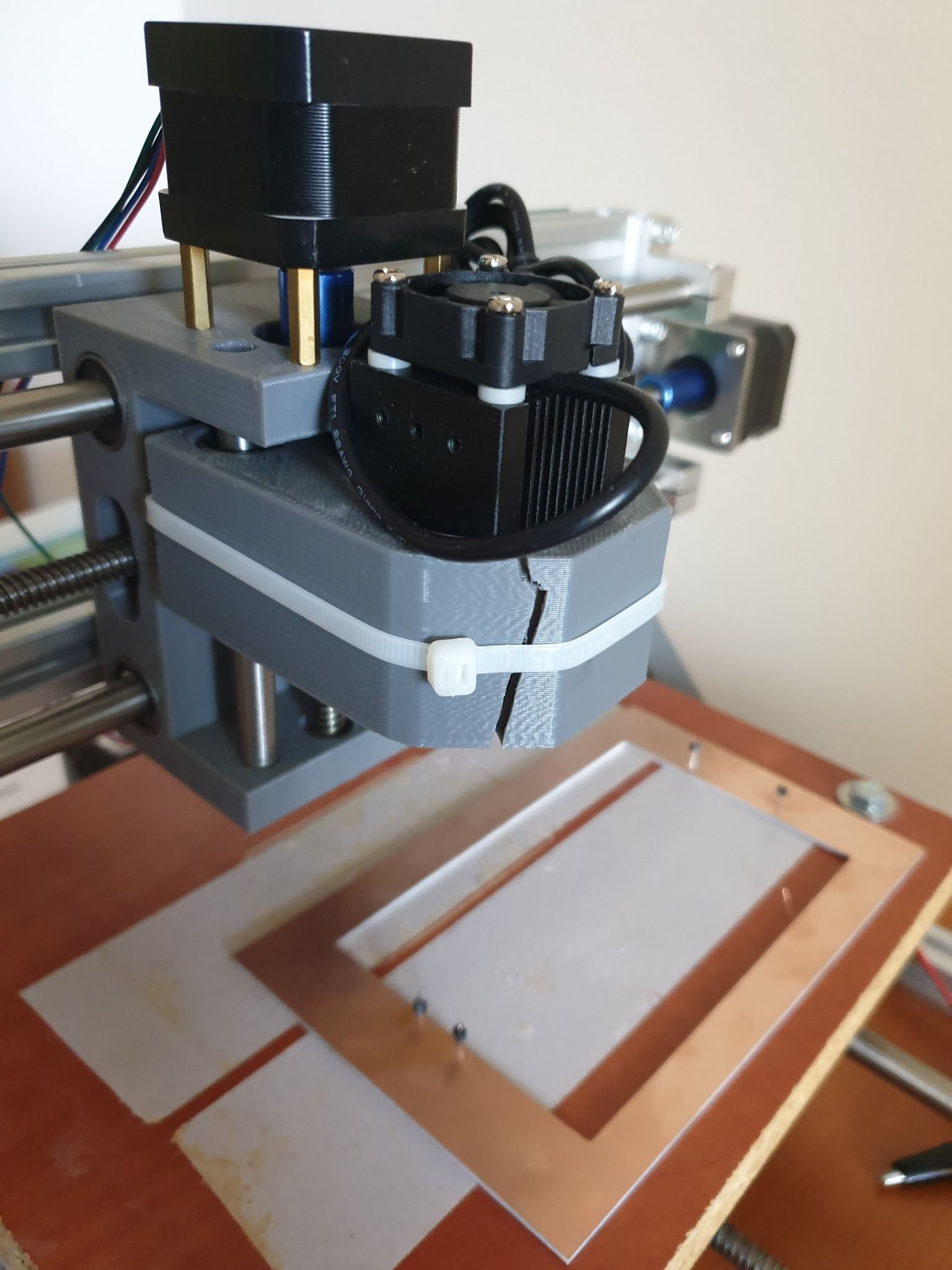
    I managed to fix the laser module with cable tie. 🙂
    It is ok for the laser, but of course not for the spindle and for the PCB milling.
    Replacement parts are available mostly in packages (e.g. https://www.ebay.com/itm/Replacement-Parts-DIY-Kit-for-CNC-1610-2418-3018-Spindle-Holder-Screw-Polish-Pod/112382449851), but it is possible to print your own version too.
    Some guys already came up with an enhanced design, such as https://www.thingiverse.com/thing:3586273

    I already wanted to make an upgrade on the CNC, so I came to a conclusion, that I will fix the broken part with a custom 3D printed one, then sell the machine.

    I already ordered my new toy, a CNC3020T (EUR 325 + shipping EUR 25):

    cnc3020t.jpg

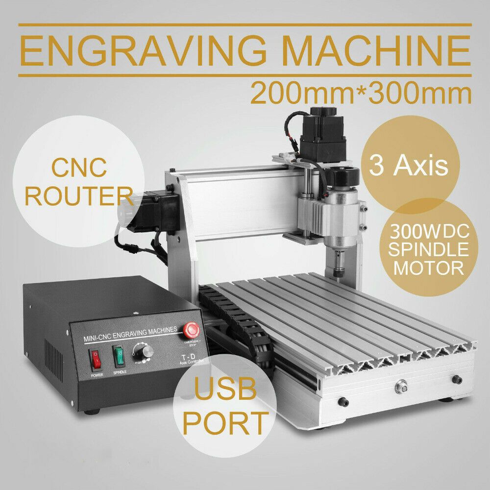
    Well, I hesitated a lot and almost bought a CNC3040Z-DQ (bigger, better, ball screw), but as currently I really don't have enough space for it (and to be honest, no reason to buy a better/bigger) I sticked with the 3020T. The quality I achieved with my 2418 will be definitely reproducible and this is enough.

    I just read the endmill isolation routing posts. Interesting stuff.
    I'm curious whether you can use smaller ones to deal with the 6mil/6mil trace/isolation sizes.

    Happy milling and cheers!


  • Hero Member

    Hi Andrew!

    Great to hear from you and your updates. 🙂

    @andrew said in CNC PCB milling:

    I'm curious whether you can use smaller ones to deal with the 6mil/6mil trace/isolation sizes.

    Yes, I'm wondering the same thing. There's reason to be hopeful that it can be done: I've seen a number of 0.1mm end mills for sale, and that's roughly the the bit diameter that would be needed. After I upgrade my stepper motors to higher torque models, and after I upgrade them even further to be closed loop, I'd like to give it a try. Fine pitched etchings like that would probably also greatly benefit if solder mask could be applied afterward, and so I'm hoping to learn how do that as well:

    https://www.amazon.com/MECHANIC-Prevent-Corrosive-Soldering-Welding/dp/B076YPKBKL

    Join the fun! With your new machine already on the way, you may be ready to give it a try before me. 😎

    When you get a chance, please do let us know how you like your new CNC. It looks a lot sturdier than the CNC that you will soon be selling.


  • @NeverDie sure, you will hear more about my new gear 🙂
    Considering the shipping time and my availability, this should happen around late August or early September!


  • Hero Member

    One more thing worth mentioning: This guy has, I think, a correct insight into why auto-leveling may not work as well in the real world as it theoretically should:

    Blank PCB material is not as rigid as it appears, depending on its size and how it was stored (not to mention how you mount it) there will be some bowing which results in a curved surface under your engraver.

    Unfortunately, the probing process doesn't put enough pressure on the board to push it down while the actual engraving process will. This means you will get shallow cuts even with an autolevelling process.

    The trick is to ensure that the probe pushes the board down to it's fully flat level before measuring the height at that point. My solution was to put a small ball on the spindle that is 2mm lower than the probe tip - as the probe moves downwards the ball pushes the PCB to the underlying bed and compresses before the probe makes contact. This gives you a far more accurate depth reading.
    https://blog.thegaragelab.com/seven-pcb-milling-tips/

    His solution looks like this:
    alt text
    which looks as though it could be improved upon.


  • Hero Member

    Recent strategy was to do multiple overlapping passes with a narrow diameter bit to get lots of isolation. It nominallly worked, but it consumed a lot of machine time. So, now testing a new strategy, which is to first do one bulk isolation with a wide bit and then do one final pass with a narrow bit to clean out whatever copper remains near the traces. Though it does require a tool change, in theory it should be faster.


  • I have found a YouTube channel that has a few video's about using the 3018 CNC for PCB milling.

    They winked a bit at the Wegstr promotional video.

    But they seem to get good quality. They also have better video's explaining the steps.

    CNC PCB - high quality with the budget 3018 CNC – 05:20
    — DIY TECH BROS


  • Hero Member

    Can anyone here explain the appeal of Mach3 in the year 2020? The premise seems to be: don't use stepper driver hardware (e.g. Trinamics) and don't use a motion controller, but instead do all the stepper motor control directly from a PC by bit-banging pins on a parallel port in real-time!? How is that a good idea, and why is it advantageous? I understand how maybe back in the day that was perhaps the most affordable way to do it, but these days? I just don't get it.


  • @NeverDie Just get any Atmega328 board (Uno, Nano) and flash grbl 1.1f and wire it to whatever drivers you have (now I'm using hybrid closed loop servos, but I've used TB6560 in the past).
    I use OpenCNCPilot, it has autolevel, and a lot of other useful functions: simplify, arc to lines, split long lines, etc. I mainly use it for splitting long lines, as a long move doesn't account for the board topography (local highs and lows), by splitting the line accordingly to the detail needed (5mm for dip, 2-3mm for smaller smd boards) I get a much better engraving. Also the autoloevel grid size and step setting is very simple.


  • Hero Member

    Hi executivul! Great to hear from you again.

    @executivul said in CNC PCB milling:

    @NeverDie Just get any Atmega328 board (Uno, Nano) and flash grbl 1.1f and wire it to whatever drivers you have (now I'm using hybrid closed loop servos, but I've used TB6560 in the past).

    On Aliexpress I notice there are these drivers (one per axis) that it sounds as though you are using. Some of them (usually blue) are self-described as "Hybrid", whereas others (often Green or some other color) are self-described as "closed loop." I haven't tried either one, but I get the impression that the "Hybrid" drivers function closed loop as well, and it sounds as though that is what you are doing. If that is the case, what, if any, functional difference is there between the self-described "hybrid" drivers and the self-described "closed-loop" drivers? I assume you know what I'm referring to, but if not, let me know and I'll post pictures and links in order to clarify.


  • Hero Member

    By the way, good news! Just yesterday I think I've identified the very same spring-loaded bit used very successfully by both Bantam Tools and Wegstr for removing DIY solder mask over solder pads. 😁 Details here: https://www.cnczone.com/forums/pcb-milling/408516-best-material-spoilboard-beneath-pcb-etching-best.html#post2395490

    For anyone not familiar with this process, here is a demo video:
    How To Make a PCB Solder Mask with the Bantam Tools PCB Milling Machine – 02:53
    — Bantam Tools

    I'll be giving it a try once my rig is upgraded and re-tuned, because obviously the z-axis height needs to be controlled very precisely for it to work without etching off the same copper pads that I'll be trying to re-expose from under the solder mask. I suppose using 2oz copper clad might also be worth it for the wee bit of added headroom. If push comes shove, I've read that even thicker copper clad PCB is available, though off-hand I have no idea where would be a good place to buy it. From what I've read the thicker cladding is most often found in PCB's made for military applications.

    Edit: Gave a quick cursory look, and both 3oz and 4oz copper clad PCB is not hard to find. Not saying it will be needed, but nice to know in case it is.


  • Hero Member

    Time to upgrade the motion controller. The woodpecker is hopeless because it takes 12v-36v input voltage and downconverts it to 12v:
    alt text
    This means you can't actually drive your stepper stick at more than 12v, even though the A4988 can use up to 36v and the DRV8825 up to 45v. The TMC5160 allows up to 60v. I'm guessing the grbl board designers did this to avoid any possibility of going over the allowed voltage, which would mean fewer warrantee returns. All well and good for them, but if I'm not mistaken, it deprives the user of snappier accelerations.

    So, I ordered just a primitive arduino shield, and hopefully it is lacking this "feature":
    alt text
    The board markings do indicate the same 12-36v range, though, but I'm guessing that's there purely either as a cautionary warning for A4988 users or because that's the highest voltage that the capacitors are rated for. Given the cramped board, perhaps trace widths are a factor as well.

    The mechaduino driver can handle voltages up to 40v, but the mechaduino board itself was designed with 36v capacitors. The MKS-servo42a has a 30v maximum according to the design they borrowed from.

    All this does make me interested in trying a TMC5160 at 60v just to see how much snappier it might be.

    Unfortunately, the uStepper (http://ustepper.com/product_sheet_revB.pdf), despite using the TMC5160, doesn't take advantage of the 60v possibility. It recommends 24v input voltage, with a 30v maximum.

    Good grief! Why, oh why, did they do that? Was it just to save a few pennies on component cost? Will I have to design my own board if I want high performance?

    I was originally hoping for this to be a drop-in upgrade. Maybe it still is, but I'm starting to have doubts about just how much of a performance upgrade I can expect from it.


  • Hero Member

    Reporting back: I received the el cheapo GRBL boards (above). The good news is that they don't have a buck converter getting in the way, the way the woodpecker does. The bad news is that the caps are rated at only 40v. So, I may replae them with ones rated for higher voltage. Also, there's a mysterious glass fuse soldered in the midst of it all. Not sure at what current it's rated to blow but, meh, probably high enough if the designer did his homework.

    So, overall, I expect this will be an improvement over woodpecker for running GRBL at higher voltage. 🙂


  • Mod

    @NeverDie judging from the images, this looks like a diode instead of a fuse.
    Anyway, keep up the good reading, I'm loving your posts 👍


  • Hero Member

    @Yveaux said in CNC PCB milling:

    @NeverDie judging from the images, this looks like a diode instead of a fuse.

    Not a bad guess based on the image you were working from, but if so it's a diode with the word "FUSE" written under it:
    alt text
    😉

    Anyway, keep up the good reading, I'm loving your posts 👍

    Thanks for the encouragement! 🙂


  • Hero Member

    The nice thing about this particular board is that there's an easy way to levitate a fan over it to cool down the stepsticks:
    alt text


  • Mod

    @NeverDie said in CNC PCB milling:

    a diode with the word "FUSE" written under it

    Got me there, but it seems to be a fuse with orientation 🤔
    We'll never know unless you put a multimeter on it 😉


  • Hero Member

    @Yveaux said in CNC PCB milling:

    @NeverDie said in CNC PCB milling:

    a diode with the word "FUSE" written under it

    Got me there, but it seems to be a fuse with orientation 🤔
    We'll never know unless you put a multimeter on it 😉

    OK, I just now probed it, and it conducts with the same 0.12 ohm resistance in both directions. So, it's not a diode. Here's a closeup photo that I took for you:
    fuse_not_diode.JPG
    I'm going to deem it a fuse unless you have a different theory or can recognize it as something else.

    Anyhow, changing topics, the good news is that the electrolytic capacitors have a higher voltage rating than what I had reported earlier. They are 100uF capacitors, and upon closer inspection it says that they are rated at 50v, not 40v as I had earlier thought. That's good news, because it means they should be able to handle the 45v maximum that DRV8825 stepper drivers can tolerate. 🙂


  • @NeverDie Did you check out the assembly instructions? There they use a fuse with a rather high current in this place 🤣 🤣 🤣
    The explanation why it is polarized is because in fact, it used to be a diode in older revisions, check out Step 7 here.


  • Mod

    @eiten said in CNC PCB milling:

    polarized

    Now it's a polarized yellow wire 🙀


  • @Yveaux said in CNC PCB milling:

    polarized yellow wire

    Oh boy, good luck @NeverDie. These are hard to get. Never saw them on Ali.


  • Hero Member

    @eiten said in CNC PCB milling:

    The explanation why it is polarized is because in fact, it used to be a diode in older revisions, check out Step 7 here.

    Yeah, let's look at that:

    D1(Diode) was intended to prevent users from damaging the board by accidentally reversing the polarity on the high voltage line. Unfortunately this feature was abandoned because I could not find a big enough Diode that would handle 6 amps at a time and still fit on the board. The work around for this is to solder in a jumper wire (Yellow Wire).

    LOL. This excuse just doesn't ring true. I mean, by version 3 he still couldn't manage to find space on the board for a suitable diode? Nevermind that he could have used an alternative for reverse polarity protection, like a mosfet, which also wouldn't have incurred as large a voltage drop.

    Well, speaking of diodes, I don't see any TVS or zener diodes on this board for protection against back EMF. I guess that's just assumed to be handled by the driver modules?


  • @NeverDie and for reverse polarity protection, you could just use a FET, a resistor and a Zener (only necessary if reversed voltage is breaking the FET, which is cheaper if you have some amps and has loooots of less power dissipation:
    mist.png
    I use this on all my PCBs with removable batterys. Luxury upgrade: a reverse voltage indicator:
    mist.png
    Add a Zener parallel to the LED if you have a wide expectet input voltage range.


  • Hero Member

    @NeverDie said in CNC PCB milling:

    speaking of diodes, I don't see any TVS or zener diodes on this board for protection against back EMF. I guess that's just assumed to be handled by the driver modules?

    Well, according to Pololu, capacitors are to be used for that instead:

    Warning: This carrier board uses low-ESR ceramic capacitors, which makes it susceptible to destructive LC voltage spikes, especially when using power leads longer than a few inches. Under the right conditions, these spikes can exceed the 35 V maximum voltage rating for the A4988 and permanently damage the board, even when the motor supply voltage is as low as 12 V. One way to protect the driver from such spikes is to put a large (at least 47 µF) electrolytic capacitor across motor power (VMOT) and ground somewhere close to the board.

    Actually, this might be better anyway, since different driver boards may have different maximum voltages, and using a capacitor would adapt to that.

    So, it remains to be seen whether the given 50v rating on a 100uF capacitor is enough if I were to raise the supply voltage to 45v to drive DRV8825's at their maximum voltage. The board design may not have accounted for that, since it sets an arbitrary limit of 36v for input voltage, as stated on the silk screen. I guess the way to test it experimentally would be to start at 35v and then creep up the voltage while monitoring an in-use capacitor in situ on an oscilloscope while driving the stepper at maximum acceleration and then suddenly stopping. I presume that would be the worst case scenario. However, I'm not sure what the gcode for that would be. Anyone know? If not, I may just have to settle for jogging the stepper around and take measurements based on that instead.


  • @NeverDie said in CNC PCB milling:

    capacitors are to be used for that instead

    Wow, thanks. I learned something today!


  • Hero Member

    I suppose the GRBL capacitor rating may soon be a moot issue anyway, as the servo42A closed loop driver accepts an input voltage of only 12-24v, and, not surprisingly, it appears to have its own back EMF cap on its driverboard:
    alt text


  • Hero Member

    Anyhow, I ordered one of these tramming tools:
    alt text
    so that I can do accurate repeatability tests on the z-axis, and that is because I will need to be deadnuts accurate if I am to selectively CNC mill the solder mask off from a PCB without destroying the underlying solder pads. i'm not sure I will have enough headroom on the z-axis to fit this tool into place--or use it for that matter--so I'll just have to see how that goes after it arrives. A lot may depend on how far I can plunge the dial indicators before they bottom out.


  • Hero Member

    By the way, I just now found a online outfit which will cnc laser cut steel up to 1" thick. Their name? Yeah, you guessed it: oshcut.
    https://www.oshcut.com
    A really interesting option for my next CNC after this one would be to design the whole thing in CAD and then have it laser cut out of stainless steel. As compared to Chinese aluminum extrusion CNC's, I can see this as having two advantages: 1. Steel is far stronger and more rigid than aluminum, and so it would be lightyears ahead in that regard, and 2. I'm guessing the parts would be far more dimensionally accurate than whatever gets banged out in China for shipment through Aliexpress. In the past what has held me back from building a CNC from scratch is the need to precisely drill all the holes with just exactlly right amount of spacing, parallelism, and perpendicularity. However, with access to cnc laser cut steel, I presumably get all the dimensional accuracy I would need at no extra cost.

    Fanciful? I think not. A kid in Poland did his own CNC design and had the steel parts lasercut in Poland. In just the past few days he finished putting it together, and it looks like a pretty reasonable design using both ballscrews and steel rail guides, held together will steel gussets that he designed himself in CAD:
    IndyMill - Open Source DIY CNC Machine #4 Final Test! – 14:53
    — Nikodem Bartnik

    I'd say it looks better than most of what China is selling. In fact, he's giving his design files away for free, so if you wanted to I suppose you could have the exact same parts lasercut and shipped to your door. Pretty cool! 😎 This looks like it could (finally!) be the start of truly open source CNC designs, as compared to the past where you more or less had to buy all the custom cut parts from somebody else, who, of course, was selling them at a mark-up relative to their own costs.


  • @NeverDie said in CNC PCB milling:

    so that I can do accurate repeatability tests on the z-axis, and that is because I will need to be deadnuts accurate if I am to selectively CNC mill the solder mask off from a PCB without destroying the underlying solder pads. i'm not sure I will have enough headroom on the z-axis to fit this tool into place--or use it for that matter--so I'll just have to see how that goes after it arrives. A lot may depend on how far I can plunge the dial indicators before they bottom out.

    Dial based tramming depends on table being flat, otherwise result is so so.
    Eventually I've used 3d printed bar with holes for 1/4" stub bit to mount into collet
    and 1/8" on other side for a scrap v-bit with probe clip attached. It allows to tram spindle in X and Y directions compared to dial gauge ( only X direction, due to not enough clerance under X axis frame)

    Yields about the same result as dial method against uneven table almost for free. Putting MDF spoil board, and levelling, helps a bit but then one gets "waves" if the spindle is not perpendicular to the table and given that MDF is not conductive, I couldn't use probe again to re-measure.

    That was solved by using steel gauge plate (I used 10x15x500mm) to serve as other end of the probe. It takes only few facing iterations to level bed with facing bit, in each direction (X and Y). Also gauge plate across whole table takes care of evening 'waves' and it's still cheaper than a good dial gauge (not speaking about dedicated tramming contraption above). Caveat is that it's much slower than using
    dial gauge due to slow probing but in my case it was more repeatable so it's hard to tell which method was slower in the end.

    With bCNC it's possible to use gcode macro to do tedious work of probing, so one needs only to manually rotate probe 180° and press a button to see which direction axis is skewed.


  • Have any of you tried to make a vacuum table?

    When it comes to the solder mask. Based on video I say this is done easier bij using UV exposure only. If you are using UV paint anyway, then you might as well print the design on a transparent sheet.


  • Hero Member

    @niallain said in CNC PCB milling:

    Eventually I've used 3d printed bar with holes for 1/4" stub bit to mount into collet
    and 1/8" on other side for a scrap v-bit with probe clip attached. It allows to tram spindle in X and Y directions compared to dial gauge ( only X direction, due to not enough clerance under X axis frame)

    Do you have any pictures you can post?


  • Hero Member

    @Joerideman said in CNC PCB milling:

    Have any of you tried to make a vacuum table?

    No, I haven't. Why do you ask?

    When it comes to the solder mask. Based on video I say this is done easier bij using UV exposure only. If you are using UV paint anyway, then you might as well print the design on a transparent sheet.

    Yes, there's more than one way to tackle the problem. The method you describe is one of the more common ones, but it seems to involve more manual processing. It would be nice if someone who had tried both methods posted the pros and cons of each method.


  • Hero Member

    @NeverDie said in CNC PCB milling:

    I suppose the GRBL capacitor rating may soon be a moot issue anyway, as the servo42A closed loop driver accepts an input voltage of only 12-24v, and, not surprisingly, it appears to have its own back EMF cap on its driverboard:
    alt text

    The original mechaduino v0.2 accepted up to 35v:
    mechaduino_voltage.png

    So, because the clone that I purchased allows for only 24v input, it's an unfortunate downgrade from the original. 😞


  • @NeverDie said in CNC PCB milling:

    @niallain said in CNC PCB milling:

    Eventually I've used 3d printed bar with holes for 1/4" stub bit to mount into collet
    and 1/8" on other side for a scrap v-bit with probe clip attached. It allows to tram spindle in X and Y directions compared to dial gauge ( only X direction, due to not enough clerance under X axis frame)

    Do you have any pictures you can post?

    Thanks to you, I finally 'finished' replacing arduino 'nano' with 'mega' 🙂 , that I were putting off for a month now, since GRBL on it provides software backlash and axis skew compensations (I gave up on trying to square/fix machine mechanically).

    Back to the topic, there are lots of videos on youtube where spindle is trammed using bar and paper method, so this is nothing new just a small improvement to reduce manual work and improve repeatability without expensive equipment.

    Before doing it, I face spoil-board perpendicular to bar to make it level,
    which results in ridges if spindle is not perpendicular to table.

    IMG_20200819_215903_1.jpg
    IMG_20200819_221234_2.jpg
    IMG_20200819_221155_3.jpg
    IMG_20200819_221253_4.jpg

    the same can be done for Y axis, just face board/turn bar 90 degrees.
    Assuming you are in EU, gauge plate I got from here, it's my source for 'cheapish' but decent endmills compared to the rest of sources, I know of, within EU.


  • Hero Member

    @executivul I notice that closed looop ethercat is also starting to become popular:
    https://www.aliexpress.com/item/33028892255.html?spm=a2g0o.productlist.0.0.4a3acc12R4bh4z&ad_pvid=202008201300179940172292214280005385422_2&s=p

    Especially for LinuxCNC and Mach3/4 users. I don't know enough about either of those software packages to know what, if any, advantages they may have, but the downside seems clear enough: you need to worry about what kind of jitter and lag the PC you run it on may have.
    Maybe that's where the closed loop helps out? The ethernet affords some noise immunity. Not sure to what degree, or not, that noise is even a problem with typical non-ethernet GRBL driven configurations.

    I notice that the new TMC5160's have motion planning built into the chips themselves, though I haven't yet seen any configurations which take advantage of that. Sounds intriguing, as it would be able to capitalize on any feedback practically instantaneously. Maybe it will be a game changer? The TMC5160 datasheet makes some vague references to closed loop.


  • Mod

    @NeverDie EtherCAT is simply awesome. Over the years I developed multiple EtherCAT masters and slaves, and used it in many industrial machine control solutions.
    It has proven extremely useful for realtime distributed control and offers great flexibility.
    Jitter on bus cycle deserves attention, but on the other hand even windows can run an EtherCAT master; it just all depends on your application and control requirements.
    In the case of small CNC and 3D printers it may be slight overkill however.
    Let me know if you would like to go deeper into the topic, or have specific questions!


  • @NeverDie These closed control loops have got really good traction lately, these days there is a sprawl of new/cheaper devices/clones. I've used mine without issue for 2 years now.
    My problem was frequent binding of the machine. I have a 60,000rpm spindle and I normally use 1400mm/min speed and 300mm/s^2 acceleration. The machine itself is far from perfect, sometimes I can hear it knocking, and with older steppers and drivers I lost a few steps every time it jammed, resulting in 0.1-0.3mm of error at the end of a longer milling process.
    The culprit is either some misalignment and lack of parallelism or some of the balls have flat spots. The binding does not occur in the same place or direction every single time, so I believe the balls are more likely to be the cause. The solution would be a complete rebuild using higher quality linear rails, but the the price and the time needed to do it makes me leave it as it is since I can mill 0.15mm isolation with 0.25mm traces for smd and also large 20cm x 30cm boards for through hole projects (mostly).


  • Hero Member

    @executivul So even with the closed loop it's still off at the end? That's hard to wrap my head around.

    I guess the ultimate solution would be DRO's then. Short of that, or the improvements you're talking about, maybe you could re-zero periodically during the job? You're getting great results, though, so I don't blame you for leaving it alone.


  • Hero Member

    @Yveaux said in CNC PCB milling:

    @NeverDie EtherCAT is simply awesome. Over the years I developed multiple EtherCAT masters and slaves, and used it in many industrial machine control solutions.
    It has proven extremely useful for realtime distributed control and offers great flexibility.
    Jitter on bus cycle deserves attention, but on the other hand even windows can run an EtherCAT master; it just all depends on your application and control requirements.
    In the case of small CNC and 3D printers it may be slight overkill however.
    Let me know if you would like to go deeper into the topic, or have specific questions!

    That's great! Do you think there's much hope of seeing a greatly cost-reduced arduino version of ethercat anytime soon? I mean, by way of analogy, for a long while wi-fi seemed intractably expensive, and even the expensive wi-fi breakouts for arduino's seemed pretty dodgy. Then out of the blue ESP8266 suddenly made good arduino wi-fi possible for cheap.


  • Mod

    @NeverDie EtherCAT requires a dedicated ASIC (e.g. Beckhoff ET1100) or FPGA IP Core.
    There have been some developments where MPU & EtherCAT slave controller were integrated into a single piece of silicon (TI, Renesas, Microchip) but these are less popular than the ET1100.
    For distributed IO it is an awesome technology, but when all IO and controller can be located onto a single board (like with most hobby CNCs) it is overkill, at least for the masses.
    But again, you never know what nice lowcost EtherCAT solution could be coming our way.


  • Hero Member

    @Yveaux That makes sense to me. If people are mainly doing it for noise immunity, I'm reasonably sure that differential op-amps (which are cheap) and twisted pair wiring (which is cheap) will do the business. That's how ethernet does it. If that's still not enough, then add shielding. Also, the more twisting the better. At least, I would think that it would be sufficient for a home environment.

    I'll be testing this theory with the closed-loop stepper drivers that I'll be installing, since with those it will be the data coms between the GRBL board and the stepper drivers that will be running across long wires instead of power pulses to the steppers, where noise didn't really matter. I guess we'll see!


  • Hey, I have trouble understanding the last 10 posts.

    It sounds like this go's beyond the PCB milling?

    What are you aiming to achieve?


  • Hero Member

    @Joerideman said in CNC PCB milling:

    Hey, I have trouble understanding the last 10 posts.

    It sounds like this go's beyond the PCB milling?

    What are you aiming to achieve?

    No, the aim is still pcb milling. More specifically: PCB milling at fine pitch and whatever might support that. Regular through-hole milling is something that just about any PCB mill can handle, so the discussion has shifted to milling for newer SMD parts, where the pitch between pads can be quite challenging for some mills, like mine for example. Then the question becomes: which are the best bang/buck upgrades (or even just calibrations) that will get you there.


  • So, I have seen that with a popular 3018 CNC a atmega328p-au can be milled.

    0.2mm traces with 0.2mm clearance can be routed.

    What specs are you going for?


  • Hero Member

    @Joerideman said in CNC PCB milling:

    So, I have seen that with a popular 3018 CNC a atmega328p-au can be milled.

    0.2mm traces with 0.2mm clearance can be routed.

    What specs are you going for?

    I thought the atmega328p had wider pitch than that, as I have etched those before. Nonethmeless, where did you see a 3018 that could do those specs? I think for now, if I'm understanding you correctly, that would be good enough, at least for me. That would effectively be a 0.4mm pitch, right? Measured center to center from one pad to the next.

    I don't think my rig is any worse than a 3018. Most low-end CNC's seem pretty similar, with aluminum extrusion frames, acme screws, round rods and inexpensive linear bearings for glides, and dubious spindles, dodgy collets, and questionable z-axis reinforcement against twisting. I guess one could look at bantam tools or wegstr for differences, as they seem to be hitting it. I doubt there's any one thing but probably a range of things done right. Perhaps being companies allows them to source parts reliably with the right tolerances, thus avoiding aliexpress roulette.

    Anyhow, I think I'll get there if I keep chipping away at it. With PCB deliveries slowing down due to covid19, it's worth the effort to figure it out. 😉

    I see working with PCB's as an advantage, because the machine itself doesn't need to be big, and in theory even (some) premium parts become affordable because the travel distances are relatively short.


  • @NeverDie

    I shared a link to this channel before.

    CNC PCB - high quality with the budget 3018 CNC – 05:20
    — DIY TECH BROS

    I am waiting for their next video. I am told it will show us a bit more about the limits of the machine.

    It doesn't actually show an atmege328 I am not sure where or if have actually seen this.

    The Wegstr, has only a Z axis for the spindle. And from what I read they use a brushless motor for this. I guess that by only moving it up and down, this part becomes very rigid.


  • Hero Member

    @Joerideman said in CNC PCB milling:

    @NeverDie

    I shared a link to this channel before.

    CNC PCB - high quality with the budget 3018 CNC – 05:20
    — DIY TECH BROS

    I'm pretty sure the pitch on the given example in that video is wider than 0.4mm.

    The Wegstr, has only a Z axis for the spindle. And from what I read they use a brushless motor for this. I guess that by only moving it up and down, this part becomes very rigid.

    Good observation. The fixed z-axis is closer to a classic mill configuration. I like that approach because it makes it easier to build rigidity into the z-axis.


  • Hero Member

    @Joerideman said in CNC PCB milling:

    So, I have seen that with a popular 3018 CNC a atmega328p-au can be milled.

    0.2mm traces with 0.2mm clearance can be routed.

    What specs are you going for?

    I looked up the atmega328p datasheet here: http://ww1.microchip.com/downloads/en/DeviceDoc/Atmel-7810-Automotive-Microcontrollers-ATmega328P_Datasheet.pdf

    The pitch on the DIP package is obviously 2.540mm.

    The pitch on the TQFP package is 0.8mm. That's the one I tend to favor because it's easy to handle, and I have a clamshell chip programmer for it.

    The ptich on the VQFN package is 0.5mm.

    On the other hand, looking at the "other' datasheet for the atmega328p: https://ww1.microchip.com/downloads/en/DeviceDoc/ATmega48A-PA-88A-PA-168A-PA-328-P-DS-DS40002061A.pdf
    it does appear to also make reference to a 28M1 package, which has only 28 pins and a lead pitch of 0.45mm. As far as the atmega328p is concerned, that appears to be the lowest pitch package. Pad width is a nominal 0.22mm, so of the various packages it's the closest to the one you said. The entire package is just 4mmx4mm in size.

    I'd be reluctant to attempt a chip that small without solder mask, but with an appropriate solder mask it would be possible I suppose. Hence, getting the solder mask part of pcb milling right is definitely important as the line pitch gets smaller and smaller, and that certainly is the trend.

    In any case, the lead pitch on the nRF52832 is 0.4mm, so there's definitely a need to accurately etch that pitch. I seem to recall running into components with even lower lead pitch than that, but offhand I can't remember which components those were.


  • Hero Member

    On another thread (https://forum.mysensors.org/topic/10812/the-harvester-ultimate-power-supply-for-the-raybeacon-dk/211?_=1598132652123) we were talking about using a laser to directly etch the copper clad on a PCB, which I think would be hard to do without a fiber laser. Nonetheless, it just now occurred to me that using a regular etching laser might be just the ticket to use for removing black solder mask over solder pads, precisely because it would fail at removing the copper underneath. After all, many people are already using this technique for removing cheap black paint (used as an acid etching mask) from copper PCBs, so I presume it would work equally well for selectively removing black solder mask? At least to me, this sounds extremely promising.


  • @NeverDie Yeah, it's a very interesting option! Similar approach might be to use a UV printer. The UV paint is known to be resistant to FeCl3 and hence results in nice and clean edges. But that's subject of paint and a laser engraver could be used over UV paint too.

    On the other hand, a fiber laser might be a nice all-in-one solution. It can do the PCB routing, can cut the board edges, and drill everything in one pass. After that, the same device can be used to manufacture solder mask using a kapton tape and also engrave the silk layer on top of it. Finally, it can cut stencils.

    The only missing part is the through hole plating. I still have concern that laser drilled the edges will be good enough for metalization, this has to be checked. But a previously drilled and plated board is much easier to etch with laser rather than a milling machine.


  • Hero Member

    @Mishka said in CNC PCB milling:

    @NeverDie Yeah, it's a very interesting option! Similar approach might be to use a UV printer. The UV paint is known to be resistant to FeCl3 and hence results in nice and clean edges. But that's subject of paint and a laser engraver could be used over UV paint too.

    On the other hand, a fiber laser might be a nice all-in-one solution. It can do the PCB routing, can cut the board edges, and drill everything in one pass. After that, the same device can be used to manufacture solder mask using a kapton tape and also engrave the silk layer on top of it. Finally, it can cut stencils.

    The only missing part is the through hole plating. I still have concern that laser drilled the edges will be good enough for metalization, this has to be checked. But a previously drilled and plated board is much easier to etch with laser rather than a milling machine.

    Somewhere out there is a product (it has a youtube video) where you pull a special paste through the via's under a vacuum and then do regular electroplating to get your vias plated. It's meant for DIY.

    I wonder if you could just squeegee fine grained solder paste into the vias and then heat it up to make the connections? I suppose you'd want to do it after the solder mask phase. If the vias are big enough, I don't see why this wouldn't work. In the worst case it might take more than one pass, and it might also have the advantage of "tinning" your regular solder pads.


Log in to reply
 

Suggested Topics

  • 4
  • 9
  • 274
  • 2
  • 1
  • 9

0
Online

11.2k
Users

11.1k
Topics

112.5k
Posts