Anyone using/tried the E28-2G4M27S 2.4Ghz LoRa SX1280 27dB module?
-
Reporting back: it turns out that accurately sawing off the upper part of the PCB was one of those "easier said than done" type of things, so I'm starting over and creating my own E28-2G4M27S breakout board in KiCAD from scratch. I wasn't a fan of KiCAD previously, but I'm finding KiCAD 6, which is the current release, is much improved! I'll post my breakout board here at mysensors after I've had it fabbed and validated that it is correct.
The datasheet for E28-2G4M27S doesn't have dimensions which show exactly where the antenna traces start and end, so I'll measure that with a micrometer and use my own measurement for that to generate the silkscreen delimiter for that region and to ensure that the copper ground plane doesn't run beneath the trace antenna. I'll be deliberately over conservative so as to better ensure there's no overlap.
-
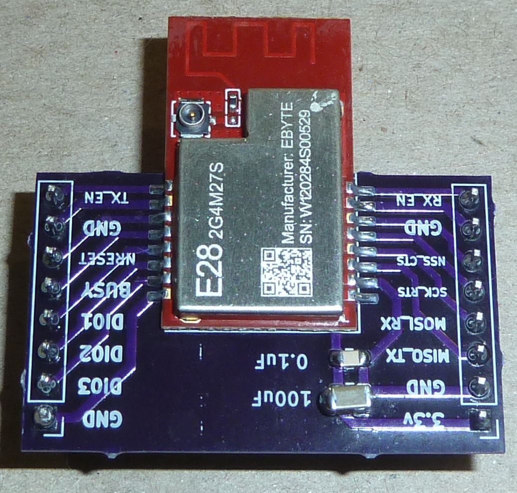
Looking at the module itself:
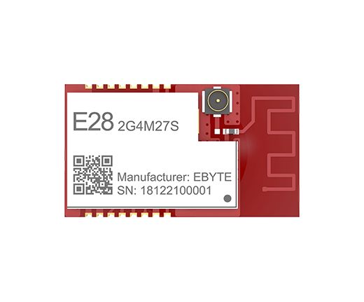
I suppose one could maybe argue that the antenna chain starts just prior to where the IPX antenna connector sits, so I'll remove groundplane from anywhere to the left of it just to be sure. Looking at the above photo, that may(?) be overkill, as it looks as though for the IPX connector to be active the resistor would need to be removed and a solderbridge installed in order to make the IPX connector active. As I'm not entirely sure though, I'll simply assume a worst case scenario and then build to that. -
Something I'm less sure about is that the author placed ground planes on both sides of the PCB:
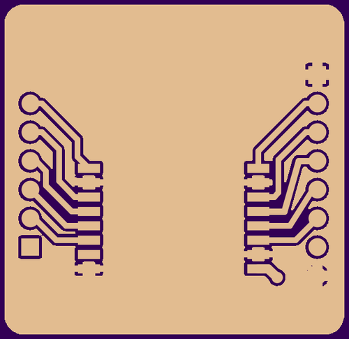
Even though the two ground planes are connected together with enough vias to make a colander, I do wonder whether this arrangement might introduce at least some amount of unanticipated capacitance. Anyone know? Is this best practice, or would it have been better to keep the ground plane on one side only?
Good to know! I found this video which I think may answer to my earlier question above:
https://www.youtube.com/watch?v=ySuUZEjARPY
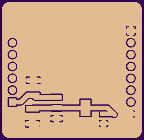
Basically, for high frequency communications, the return path in the ground plane is directly beneath the trace. For this reason, rule #1 is to never route across splits in the ground plane:
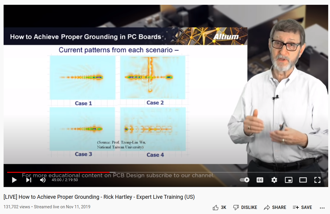
Therefore, for a two sided board, the ideal would be to have a prestine ground plane on the bottom layer. Adding another "ground plane" on the top layer is effectively an oxymoron. According to the presenter, routing across a split in the ground plane, as in the cut channel of case #2, can cause considerable EMI problems.
-
Here's the breakout board for it that I just now made using KiCAD version 6: https://www.openhardware.io/view/8304/E28-2G4M27S-24GHz-LoRa-Breakout-Board
IMHO, this breakout board should be much better than the breakout board done by the other guy that I referenced earlier in this thread. -
Here's the breakout board for it that I just now made using KiCAD version 6: https://www.openhardware.io/view/8304/E28-2G4M27S-24GHz-LoRa-Breakout-Board
IMHO, this breakout board should be much better than the breakout board done by the other guy that I referenced earlier in this thread.@NeverDie - I gotta say the Rick Hartley video has been really helpful to understand ground planes. At about 14:00 he nails it: "the energy is in the field". When learning electric-magnetic force, I didn't think that the energy is in the field (i.e. magnetic). I only have 2 hours to go to learn more! Thank you.
-
Here's the breakout board for it that I just now made using KiCAD version 6: https://www.openhardware.io/view/8304/E28-2G4M27S-24GHz-LoRa-Breakout-Board
IMHO, this breakout board should be much better than the breakout board done by the other guy that I referenced earlier in this thread.@NeverDie Sorry to bother again... but I gotta say this Hartley traning video has been monumental. I always thought the world was divided into AC and DC. NOW, I think I get it: DC circuits flipping on and off at a SIGNAL frequency are actually AC just with a different voltage basis. The KEY, Hartley says, is that the energy is not in the trace, but in the field during the rise and fall of voltage. This is also helping me to finally understand inductance. WHY didn't they say this 40 years ago in school? Oh, perhaps I was sleeping as I did.
This is a breakthrough that may lead me to understanding antennae theory and a bunch of other stuff. I thank you for the introduction. I gotta go find this Hartley fellow to thank him. -
@NeverDie Sorry to bother again... but I gotta say this Hartley traning video has been monumental. I always thought the world was divided into AC and DC. NOW, I think I get it: DC circuits flipping on and off at a SIGNAL frequency are actually AC just with a different voltage basis. The KEY, Hartley says, is that the energy is not in the trace, but in the field during the rise and fall of voltage. This is also helping me to finally understand inductance. WHY didn't they say this 40 years ago in school? Oh, perhaps I was sleeping as I did.
This is a breakthrough that may lead me to understanding antennae theory and a bunch of other stuff. I thank you for the introduction. I gotta go find this Hartley fellow to thank him.@Larson Glad you liked it. If you're interested in the theory of it, then you may find this a worthwhile survey of some of the big ideas:
https://www.youtube.com/watch?v=bHIhgxav9LYPlainly it's a deep topic, so I'm relieved whenever I find simple design rules of thumb which make it possible to do successful projects without having to peel back everything to first principles. ;-)
-
@Larson Glad you liked it. If you're interested in the theory of it, then you may find this a worthwhile survey of some of the big ideas:
https://www.youtube.com/watch?v=bHIhgxav9LYPlainly it's a deep topic, so I'm relieved whenever I find simple design rules of thumb which make it possible to do successful projects without having to peel back everything to first principles. ;-)
@NeverDie Yes, I strive to not reinvent also. But it is nice to know why wheels are round. So I dug a little further on this ground plane subject and I’m conflicted. At 40:42 on this video, ground planes are discussed. In short, he discourages the use of ground planes. So I ask myself, what design is used on an ESP8266 itself. Certainly, they use the best design standards to minimize EMI since they manufacture these radios by the millions. To find out I get out my zacto knife and scrape off some of the masking of the ESP and check for ground. Sure enough they use ground planes everywhere except for under the antennae. Go figure.
[Edit 5/30/22. After listening to the link in my post again, I’m realizing that I was wrong to say Eric Bogatin discourages ground planes. I think I’ve learned that he discourages the use of copper fills on signal layers. Big difference. It was unclear in the referenced video segment that the three experimental boards with different trace distributions had a ground plane below, but I believe that was the case.]
-
@NeverDie Yes, I strive to not reinvent also. But it is nice to know why wheels are round. So I dug a little further on this ground plane subject and I’m conflicted. At 40:42 on this video, ground planes are discussed. In short, he discourages the use of ground planes. So I ask myself, what design is used on an ESP8266 itself. Certainly, they use the best design standards to minimize EMI since they manufacture these radios by the millions. To find out I get out my zacto knife and scrape off some of the masking of the ESP and check for ground. Sure enough they use ground planes everywhere except for under the antennae. Go figure.
[Edit 5/30/22. After listening to the link in my post again, I’m realizing that I was wrong to say Eric Bogatin discourages ground planes. I think I’ve learned that he discourages the use of copper fills on signal layers. Big difference. It was unclear in the referenced video segment that the three experimental boards with different trace distributions had a ground plane below, but I believe that was the case.]
@Larson AFAIK, the biggest reason to have a ground plane in a radio system is to improve the performance of a whip antenna. I'm not sure what's ideal, but, for example, https://www.digi.com/support/knowledge-base/does-a-1-4-wave-antenna-need-a-ground-plane recommends a 3 inch radius groundplane for a 2.4Ghz radio if the antenna were put in the very middle of it. Well,that would be a 6 inch diameter ground plane! Not a great option for tiny IOT devices.
Fortunately, it does concede that "The antenna can still work on a smaller ground plane but the efficiency will be reduced." On the other hand, if you're using a dipole antenna, then maybe (?) the ground plane isn't so important. Not entirely sure.Anyhow, if you find out anything more, I'd be interested.
-
I'm an engineer, though not RF. My understanding, from short discussions years ago with RF engineers, was that the ground planes have strong effects on antenna performance.
Depending on the design of the antenna, sometimes you want the ground plane and sometimes you don't.
But that's the extent of what I remember. (And it could be that I've even got errors in that little bit.) But basically to go with whatever the antenna designer recommended, because there are reasons for it. Just because one design calls for it and the other doesn't, it doesn't make either of them wrong.
Without the deep understanding myself, and not having however much testing equipment necessary to check the results, I try to stick as close to what the manufacturer/designer calls for as possible.
@NeverDie and @ejlane: Thanks for the inputs. Wise counsel has been my easy path, too, especially in engineering (Civil by profession, but wannabe Electronic in my retirement). @ejlane: I ran across NeverDie and MySensors in my earlier radio research (RFM69’s I think) and fast embraced his advice & learnings. And I admire his clear writings/descriptions.
After digesting the content of this thread and having time to sleep on it I’m starting to think that signal integrity (EMI) and antennae performance are maybe the same thing on different ends of a design spectrum. So perhaps both ground planes and non-ground planes are just different design criteria for different purposes (transmission vs. noise immunity).@NeverDie - yep, 6-inch GP will sink my little boards. Funny that the RFM69's do so well with such a tiny board and whip antennae. I haven't scraped the masking on those radios looking for GP's, however.
Someday I'll grow-up and buy a scope. Discussions like this really help – thanks.
-
I'd say that EMI is just transmitting accidentally. Parts of the circuit are radiating when you didn't mean them to. When that accidental radiation - which is unavoidable at some level - rises above the regulation limit for any frequency band then you have FCC (or other country alternative agency) problems. Of course the accidental emissions can also be just about any frequency, depending on trace length and shape, clock speeds, etc. That again might require antenna knowledge to know what to expect.
-
@Larson AFAIK, the biggest reason to have a ground plane in a radio system is to improve the performance of a whip antenna. I'm not sure what's ideal, but, for example, https://www.digi.com/support/knowledge-base/does-a-1-4-wave-antenna-need-a-ground-plane recommends a 3 inch radius groundplane for a 2.4Ghz radio if the antenna were put in the very middle of it. Well,that would be a 6 inch diameter ground plane! Not a great option for tiny IOT devices.
Fortunately, it does concede that "The antenna can still work on a smaller ground plane but the efficiency will be reduced." On the other hand, if you're using a dipole antenna, then maybe (?) the ground plane isn't so important. Not entirely sure.Anyhow, if you find out anything more, I'd be interested.
@NeverDie said in Anyone using/tried the E28-2G4M27S 2.4Ghz LoRa SX1280 27dB module?:
Anyhow, if you find out anything more, I'd be interested.
Eric Bogatin, master and professor of signal integrity, gave this presentation at an Altuim conference. At about 42:00 he talks about 7 Habits of Good Design. This, again, has more to do with PCB design and not radio performance. I have a suspicion that several radio boards I designed failed not because of the transmitter, but because of bad PCB design. I can make a failed transmitter (whip antennae) board work by putting the 433 MHz transmitter on a 7" leash away from the board. Now that is a sign.
@ejlane - Thanks. I'm just now learning of the EMI/EMC testing required for commercial products and FCC requirements. While that exceeds the requirements and budget for my home projects, I do think that I might employ the pre EMI testing that one can do with a scope and probes. That may drive me back to school to learn scopes!
-
@NeverDie said in Anyone using/tried the E28-2G4M27S 2.4Ghz LoRa SX1280 27dB module?:
Anyhow, if you find out anything more, I'd be interested.
Eric Bogatin, master and professor of signal integrity, gave this presentation at an Altuim conference. At about 42:00 he talks about 7 Habits of Good Design. This, again, has more to do with PCB design and not radio performance. I have a suspicion that several radio boards I designed failed not because of the transmitter, but because of bad PCB design. I can make a failed transmitter (whip antennae) board work by putting the 433 MHz transmitter on a 7" leash away from the board. Now that is a sign.
@ejlane - Thanks. I'm just now learning of the EMI/EMC testing required for commercial products and FCC requirements. While that exceeds the requirements and budget for my home projects, I do think that I might employ the pre EMI testing that one can do with a scope and probes. That may drive me back to school to learn scopes!
@Larson As far as I know, it takes special probes for magnetic fields to check for EMI. Never done it myself, but I keep meaning to. :)
But scopes are well worth it to see what's going on. You can make it a fair ways with just fiddling with the dials and some light watching of YouTube. I used scopes a bit here and there before I ever went to school for engineering. (Though there was no YouTube to learn from at the time. The basics are pretty self-explanatory, and the advanced features are still beyond what I really do sometimes.)
-
Good news. Regarding the SHT45 TH sensor I mentioned in the first post, mouser expects to have it in stock by July 29, 2022: https://www.mouser.com/c/?q=sht45 Quantity 1 price is $4.60. AFAIK, in terms of accuracy and precision and measurable range, it's pretty much state of the art. If anyone knows of anything better, please do post what it would be.
A bit like the DeLorean in Back to the Future, I figure if you're going to build a TH sensor, might as well do it in style!
-
I've had the board fabricated, and I've verified that the through-holes will correctly line-up with the holes on a 2.54 pitch prototypig board. Also, the landing pads appear to line-up perfectly as well. Therefore, I have removed the "work in progress" tag. The breakout board is done!
https://www.openhardware.io/view/8304/EBYTE-E28-2G4M27S-SX-1280-chip-24GHz-LoRa-Breakout-Board
-
I just now noticed that Andreas Spiess did a youtube about the same chip, though different model Ebyte modue:
https://www.youtube.com/watch?v=JYThKZCflJcSmall world: it turns out he also made a breakout board for himself in order to test the module. It doesn't look pin compatible with my module, however, as it has only 14 pins on its pinout, whereas mine has 16. Also, not sure whether Andreas posted his breakout board anywhere. I would expect so. He has a github, but it has almost no descriptive material in it other than the titles, so it's hard to know what is truly what.
Worthy of note: the module he chose is less capable than the one I picked: substantially less potential transmit power, and also, according to Ebyte specs, somewhat inferior receive sensitivity.
Fortunately, he does post links to the libraries that he used to operate the SX1280 chip, so that's probably a good starting point, or at least a point of comparison.
To avoid interference he does report having to turn off the wifi on his esp32 that's driving the module, so having an ethernet connection for the gateway probably makes the most sense. The good news is that with LoRa, you should need only one such gateway, and you can probably put it just about anywhere and still have a good, solid RF connection to your nodes. Probably a raspberry pi could serve that purpose for a low effort solution, though I may go for an arduino-ethernet solution because that may turn out to be even easier, and probably without the need for ongoing updates and security maintenance. i.e. it should "just work". Perhaps setting the target IP address with a dipswitch would avoid any future need to revisit the firmware. Also, a raspberry pi's attack surface seems orders of magnitude larger than a more basic, hardware oriented solution.
Regardless, the next step for me is to wire it up and get it to play ping pong with another node. Then I'll be able to quickly determine whether ambient wi-fi signals in the environment will be a cause for concern or not. I suspect not, but sending thousands/millions of test packets while measuring for packet loss will tell the tale definitively.
I have one node with a 100uF capacitor (pictured in my preceding post), and another node without, so I'll try to determine whether it makes any practical difference or not. I'm guessing that it were powered by a coincell, it's essential, but if by two AA's in close proximity, probably not (though if the batteries are weak, maybe it would, at the margin, still help).
-
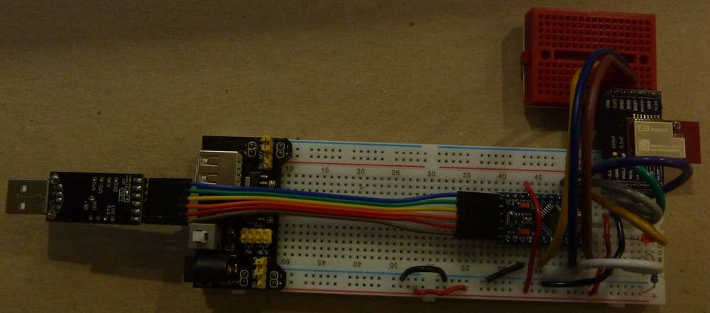
Here's what the breadboarded LoRa transmitter node looks like:
It turns out you need an external LED for status purposes, because the typical Pin 13 LED isn't available because it's in use by the SPI interface as a clock pin. The LED blinks every time a packet is transmitted (about once a second). In the picture here, I managed to photograph it at the very moment of blinking after a transmission.
The wiring pinout is given in the header file of the library example application, so no thinking required. I'm using a generic pro mini with the 5v LDO removed, and I then programmed it using the Arduino IDE as a 3.3v 8Mhz pro mini using the library's example transmitter setup sketch downloaded from: https://github.com/StuartsProjects/SX12XX-LoRa
-
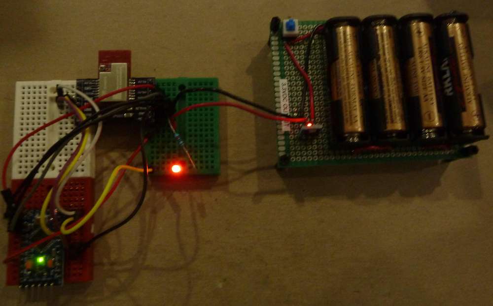
Here's what the breadboarded receiver looks like:
Every time it receives a packet from the transmitter (pictured in the immediately preceding post), it blinks the red LED.
Simple to assemble. Both transmitter and receiver worked flawlessly the very first time I put it all together. :-)
Next up: do range testing around the house and run enough packets to determine whether any ever get lost, and, if so, what the rate of loss is. I'll also dial down the transmit power to see how low is still sufficient.
Hello! It looks like you're interested in this conversation, but you don't have an account yet.
Getting fed up of having to scroll through the same posts each visit? When you register for an account, you'll always come back to exactly where you were before, and choose to be notified of new replies (either via email, or push notification). You'll also be able to save bookmarks and upvote posts to show your appreciation to other community members.
With your input, this post could be even better 💗
Register Login