Anyone using/tried the E28-2G4M27S 2.4Ghz LoRa SX1280 27dB module?
-
@NeverDie Hi, I've just started playing with a pair of these modules that I've had kicking around for a while. Fascinating thread and I haven't finished reading through yet, thanks for being so thorough!
I'm using the same library. When it comes to enabling the TX_EN and RX_EN pins, can you clarify how? Is it done through the microcontroller script, or by setting the pin inputs to high (+3.3v)?
@samh For the receiver node, I simply wired RX_EN to 3.3V and TX_EN to GND. For the transmitter module, I found that wiring TX_EN direcctly to 3.3V doesn't work so well (probably too high a duty cycle for the PA to be operating continuously like that), so I instead wired TX_EN to a spare pin and I modified the code so as to drive that pin HIGH just prior to transmitting and drive it to LOW when done transmitting. Also, on the transmitter node I wired RX_EN to ground. This seemed to work. However, it reminds me now that this was really just improvisation on my part for expediency in getting something setup fast.. Perhaps I should be using pull-up and/or pull-down resistors instead. Thanks for bringing up this topic! I'll investigate further. Please do post what you end up using youself, as well as whether you are getting similar or different results regarding noise (SNR) and/or range.
-
Reporting back: It turns out that in the settings.h file, you can assign pins for TX_EN and RX_EN. I assigned Arduino pin 4 for TX_EN and pin 5 for RX_EN, and it works fine.
I also inserted 10K resistors as a "just in case". I also increased TX_POWER to 10.
I'm not sure which of the 3 changes made the most difference, but the result is noticeable improvement. SNR is still reported as low., but I am now getting reliable longer range than previously. Maybe SNR is just not measured accurately by the module?
IIRC, the module has two forms of integrated step-down within the chip: an LDO and a buck converter. Not sure which one the library defaults to (I'll have to look it up) but if it's the buck, then switching over to the LDO might help with the SNR.
[Edit: I just now checked, and the library defaults to using the LDO rather than the buck converter]
-
Last update: I changed frequencies to 2.42Ghz, and SNR became a bit better, so maybe interference in the 2.4Ghz band really does play a role. It still performs much worse than the 915Mhz LoRa nodes I i discussed above however. At this point the next noticeable improvement, if anything, probably won't happen until I fab the custom low noise PCB which I showed above.
-
Thanks for letting me know, I'm going to play around with these over the weekend and I'll try to report back. Not too bothered about getting optimal performance since it's my first time messing with RF specifically in an arduino project, just want to do some basic testing. Some 868 modules are for sure on my list to check out next
-
Regarding the 915Mhz SX1262, the Dorji brand seems interesting. They sell two different module types: one, the DRF1262T, with a TCXO at 1ppm, and one, the DRF1262G, with a non-TCXO crystal (uses less power) which they say is 10ppm. They also have a breakout board for Arduino Uno to facilitate testing:
https://www.ebay.com/itm/192665058568
https://www.ebay.com/itm/202574135410
https://www.ebay.com/itm/202436579399So, in addition to the AI-Thinker Ra-01SH modules, I've ordered some of these DRF1262T/G to compare performance. Hopefully at least one of the three different models will be a winner.
-
Last update: I changed frequencies to 2.42Ghz, and SNR became a bit better, so maybe interference in the 2.4Ghz band really does play a role. It still performs much worse than the 915Mhz LoRa nodes I i discussed above however. At this point the next noticeable improvement, if anything, probably won't happen until I fab the custom low noise PCB which I showed above.
@NeverDie, Thanks again for all the blogging on this subject. If you have not yet ordered your custom low-noise PCB, I had one design idea. If you flip the ProMini orientation end over end most of the traces will be shorter, especially the RX/TX lines. I’ve not examined the code, but I’d think that the RX/TX connections have the most signal activity on the board, thus EMI potential. I like how you keep all the traces on one side. That should solve the interrupted ground-plane problem we learned from Rick Hartley above.
It is far more fun to roll-your-own. Alternatively, I was thinking … I just checked the Moteino breakout boards from Felix at LowerPowerLabs to see if those would work with your Ebyte radios: too bad, different pinout. I just bought a few Moteinos (915 mhz) boards to save myself from my low-quality solder jobs and shaky hands – only $13 but I have to add my own radio or spend another $7. Everything I've seen from LowPowerLabs has been high quality.
-
I've finally made a little progress over the last two days. Lots of background reading on the excellent SX12XX library and some tinkering to make a portable radio modem for future testing
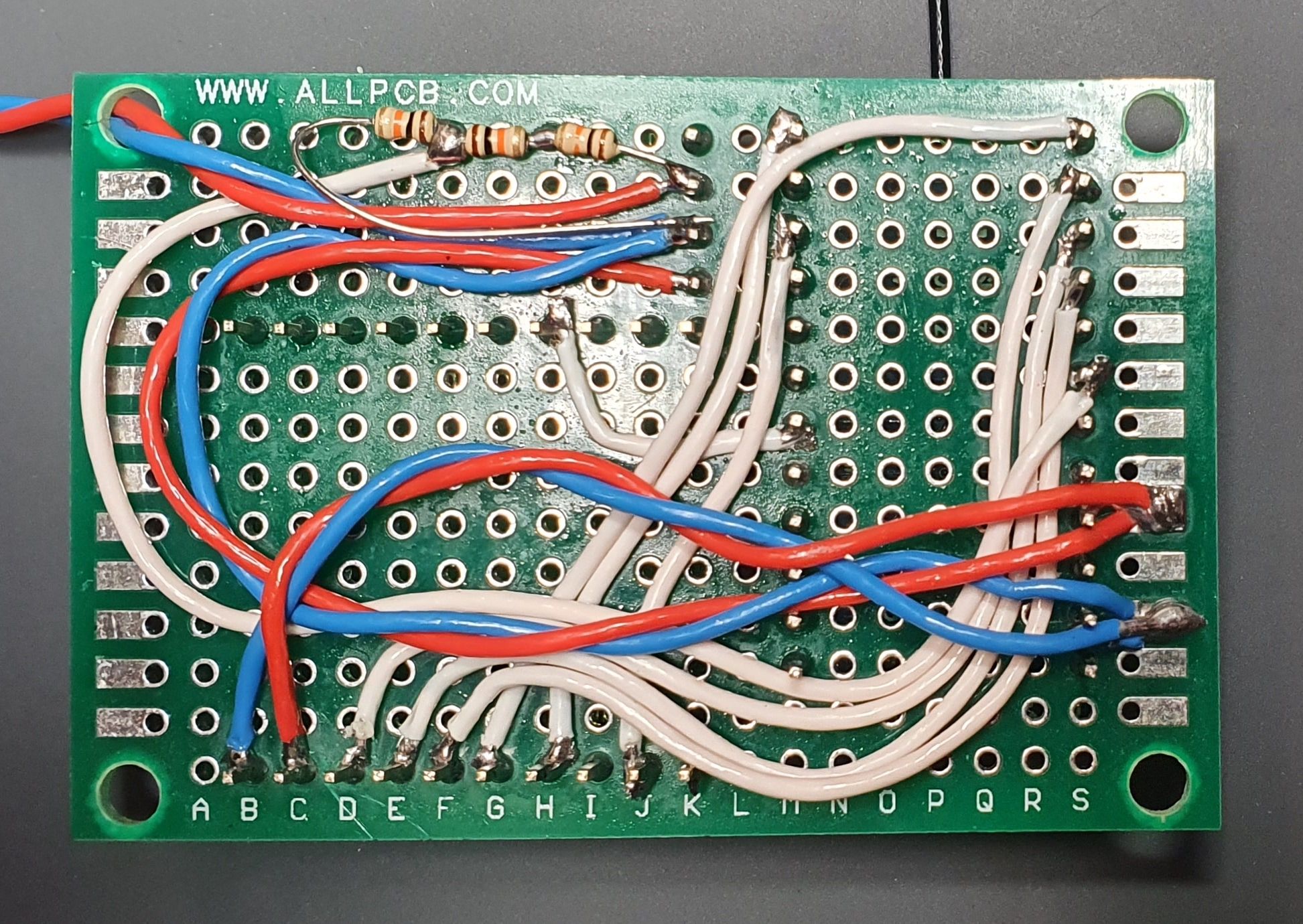
Here's the transmit end soldered up to a little bit of prototyping board I had lying around, which it turned out was the perfect size to fit the E28+breakout, Arduino Pro Mini, and voltage reg! All powered off a tiny 2S LiPo at the moment. The antennas are external Happymodel ELRS-intended and are supposedly 5dB...
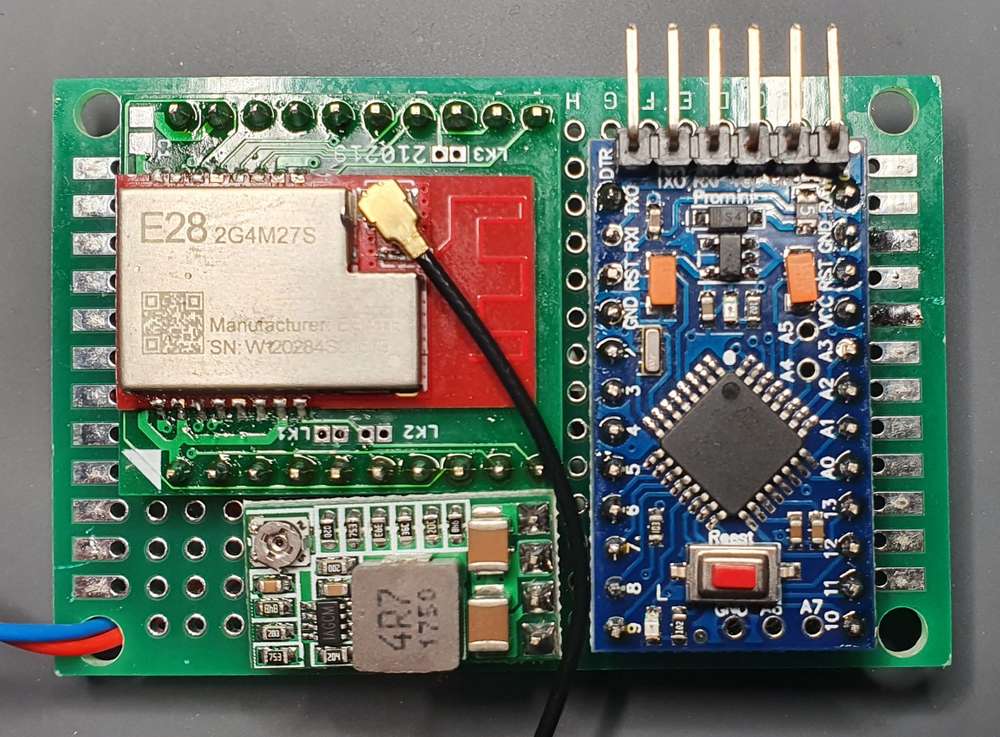
The voltage divider is included for battery monitoring. I modified the 'varying power' library examples (numbers 10/20) to include sending one battery voltage packet per test and print serial bytes in a slightly more interpretable format for a python script to read and save to csv.
Just as a proof of concept, I looked at how RSSI/SNR vary with Tx power and RF attenuation, see below:
- TC1 = line of sight, 3-4m separation
- TC2 = as TC1 but cross-polarised antennas
- TC3 = several brick walls of attenuation
- TC4 = as TC3 but cross-polarised antennas
(and yes, the axes are intentionally the wrong way around since it's easier to fit the plots on a horizontal screen this way!)
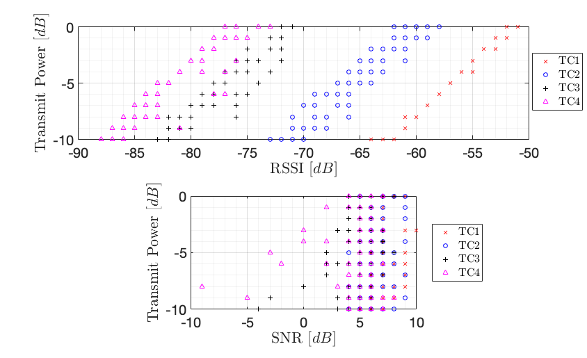
Clearly something is working right as RSSI drops off linearly with Tx power! SNR performance leaves a bit to be desired but seems that @NeverDie had similar results. Not very exciting but showing the setup is correct for now and I can move on to some more interesting things.
Next up is to have a look at implementing the PA/LNA on the E28 modules and seeing what kind of difference I get in performance. Spotted the RX/TX_EN pins in the library documentation so I'll give those a go
-
@NeverDie, Thanks again for all the blogging on this subject. If you have not yet ordered your custom low-noise PCB, I had one design idea. If you flip the ProMini orientation end over end most of the traces will be shorter, especially the RX/TX lines. I’ve not examined the code, but I’d think that the RX/TX connections have the most signal activity on the board, thus EMI potential. I like how you keep all the traces on one side. That should solve the interrupted ground-plane problem we learned from Rick Hartley above.
It is far more fun to roll-your-own. Alternatively, I was thinking … I just checked the Moteino breakout boards from Felix at LowerPowerLabs to see if those would work with your Ebyte radios: too bad, different pinout. I just bought a few Moteinos (915 mhz) boards to save myself from my low-quality solder jobs and shaky hands – only $13 but I have to add my own radio or spend another $7. Everything I've seen from LowPowerLabs has been high quality.
@samh Great stuff! I look forward to hearing more. As you probably know, the buck/boost converter (whichever it is) that's in your photo is a possible source of noise. I can't say whether, in reality, it would be or not. That's one of the reasons why (below), I'm planning to run directly from batteries only.
@Larson Good suggestions. I decided to dump the pro mini idea and just make my own barebones pro mini, because pro mini's come with three things that aren't useful and actually get in the way: 1. the LDO, 2. the oscillator, and 3. the LED on pin 13. I'm hoping (but haven't confirmed) that by eliminating the oscillator on pins D20 and D21, I can use those pins to drive two LED's kinda "for free" since nobody uses those pins for anything. So, the first draft looked like this:
to get the shortest possible lines, like you said. It also includes a TPL5010 as an ultra low current wakeup timer. The main thing, though, is that it runs from two AA batteries, which are directly attached to the PCB itself. Well, this design was working out fine, but it seemed a bit tedious to redo it for each possible radio I wanted to test, so I think I'm settling on this instead as a test platform:
which amounts to a stripped down pro mini (plus two I2C pinsout at the bottom for plugging in a TH sensor, or whatnot). In this case, the idea is to do a simple breakout board for each radio and connect it as a shield to the unused pins on the atmega328p. I figure it should be easier than doing a complete, fully integrated board for each radio. And I like that it's of minimal size (the footprint of two AA batteries), yet packs enough power that I expect it should have no trouble supplying even 200ma if needed just from the batteries themselves.I'm lucky in that I have a Dragon programmer, so I can both burn the bootloader and set the fuses on the atmega328p prior to soldering it into place on the PCB. From past experience, the sleep current on the atmega328p itself can be as low as 100na. In the past when Pro Mini's sold for only a buck, I leaned toward using Pro Mini's for everything. These days I guess I'll roll my own.
I think eventually I want to replace the canonical 6 pin FTDI connection with a 5 pin picoblade. I've only just started looking into that. I was favoring the idea of using 1.0mm pitch JST-SH conectors for the task, but sourcing them didn't look easy. So, I'm reluctantly settling on the 1.25mm pitch picoblade instead. If there exists something even more compact (maybe some kind of 2x3 row of pins on a connector), then I'd be keen to hear what it is.
The AA battery connectors are the Keystone 92, which look like this:
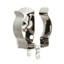
In the end, it might look like an improved variation of one of these:
https://www.openhardware.io/view/395/LoRa-Ra-01-ATmega328P-Node
https://www.openhardware.io/view/268/Arduino-Pro-Mini-Shield-for-RFM69HW
https://www.openhardware.io/view/480/Compact-nRF24L01-Pro-Mini-Bottom-Shield
but this time a bit more of a general purpose razor and blades system, if you catch my meaning. This time it will be a little wider than a pro mini, so it will be possible to fit any radio onto the shield. That said, I always liked the simplicity and ease of assembly of the "LoRa Ra-01 ATmega328P node". Perhaps the biggest improvement is the tight integration of the batteries, which in most designs are left "flapping in the breeze" as an afterthought for the builder to sort out.Anyhow, I have a bit more work to do, but that's the current evolution. As always, any thoughts, reactions, suggestions, or feedback appreciated.
-
@NeverDie. You are way out there, man! Thanks to the references to the other boards made by you. What fantastic contributions to the maker market.
I suppose D20 and D21 are the same as PCINT6/XLTAL1 and PCINT7/XTAL2? I once reassigned RX and TX on an Attiny85 toRX and TX(edit: output functions) as I was pin limited. It took some doing, but that is the beauty of these multifunction pin assignments. The code, if I remember, had to be in the loop after a delay in the setup; that gave me a way to access the RX/TX pins again to reprogram if necessary. Maybe there are similar challenges with bypassing the crystal.
@samh. So you are setting power levels on the fly. Very clever. -
I've finally made a little progress over the last two days. Lots of background reading on the excellent SX12XX library and some tinkering to make a portable radio modem for future testing
Here's the transmit end soldered up to a little bit of prototyping board I had lying around, which it turned out was the perfect size to fit the E28+breakout, Arduino Pro Mini, and voltage reg! All powered off a tiny 2S LiPo at the moment. The antennas are external Happymodel ELRS-intended and are supposedly 5dB...
The voltage divider is included for battery monitoring. I modified the 'varying power' library examples (numbers 10/20) to include sending one battery voltage packet per test and print serial bytes in a slightly more interpretable format for a python script to read and save to csv.
Just as a proof of concept, I looked at how RSSI/SNR vary with Tx power and RF attenuation, see below:
- TC1 = line of sight, 3-4m separation
- TC2 = as TC1 but cross-polarised antennas
- TC3 = several brick walls of attenuation
- TC4 = as TC3 but cross-polarised antennas
(and yes, the axes are intentionally the wrong way around since it's easier to fit the plots on a horizontal screen this way!)
Clearly something is working right as RSSI drops off linearly with Tx power! SNR performance leaves a bit to be desired but seems that @NeverDie had similar results. Not very exciting but showing the setup is correct for now and I can move on to some more interesting things.
Next up is to have a look at implementing the PA/LNA on the E28 modules and seeing what kind of difference I get in performance. Spotted the RX/TX_EN pins in the library documentation so I'll give those a go
@samh My first reaction is that your SNR is better than mine, especially for the measurements of going through several brick walls--though it's a bit hard to read the TC1-4 symbols when they're printed over one another, so I'm not completely sure. Since you also have some longish wires, I wouldn't be at all surprised if the cheap breadboards I used are, in one manner or another, impairing my SNR. This is where comparing notes can really be helpful. Thanks!
Despite China's lockdown, it looks as though my Ra-01SH modules may be here before long, so I want to get my test PCB orders in soon!
Looking forward to finally having a single test bed for comparing the performance of different radios modules! i.e. the only thing to change from one test to another will be the radio (and possibly software). For instance, it will be nice to know that when the bits "absolutely, positively, have to get there", which radio can do it reliably but also with the least amount of total energy? I mean, LoRa has the promise of great range, but the transmission time can be so long that may come at a pretty high energy price.... unless maybe the link budget allows the Tx power to be hugely reduced. That's what I'd very much like to know. i.e. which is ultimately better, if the figure of merit is energy spent per successfully delivered bit? FSK or LoRa? Or something else? Probably somebody out there in industry or the military or in academia has studied this question using the best equipment (or at least simulations) and published about it, but nothing beats real empirical results from whatever gear you have in your actual hands--because at the end of the day that's all you have to work with anyway. The cool thing is that the Semtech chips can do both FSK and LoRa, so you have the option to choose whatever best fits the situation, or switch back and forth depending on changing conditions. Ask near as I can tell, the FSK component of the Semtech LoRa radio chips is, essentially, an improved form of the RFM69's radio (which is also made by Semtech). My guess is that if you can get your packets delivered at 2mbps using an NRF24L01 (or equivalent NRF5x), then that's going to be the most energy efficient delivery method. But, if that doesn't work reliably enough, what's your next best option to get your bits delivered, and your next best option after that, etc.? And it's not just that: you need to compare sleep current consumption and wake-up times as well. Fun fact: when in the past I ran the numbers for mostly sleeping sensor devices, most often it's the sleep current consumption that dominates.
-
@NeverDie Haven't you heard of the chip shortage? It's changed everything, and prices for those things that are even available have generally gone up. (Though somehow magically, the ESP32 seems to be pretty much untouched. You can still buy them, and prices have been relatively stable. I don't know how they've done it.) AVR, PIC, STM chips have all been hard to get specific models, and at times any model that has the features. I expect other brands were similar, but those are the ones that I've looked for.
I hope they someday go back, but for the foreseeable future, expect it to be like this.
Pro minis for close to $1 was always a shock, since even at 1k qty, just the chip itself costs more than that. So to get to that price for the whole assembled board, there must be some kind of gray-market thing going on. If I were to try to make a profit on 1k at a time, assembled and everything, I'm pretty sure the final price would have to be in the ballpark of $10 each.
@ejlane said in Anyone using/tried the E28-2G4M27S 2.4Ghz LoRa SX1280 27dB module?:
@NeverDie Haven't you heard of the chip shortage? It's changed everything, and prices for those things that are even available have generally gone up. (Though somehow magically, the ESP32 seems to be pretty much untouched. You can still buy them, and prices have been relatively stable. I don't know how they've done it.) AVR, PIC, STM chips have all been hard to get specific models, and at times any model that has the features. I expect other brands were similar, but those are the ones that I've looked for.
I hope they someday go back, but for the foreseeable future, expect it to be like this.
Pro minis for close to $1 was always a shock, since even at 1k qty, just the chip itself costs more than that. So to get to that price for the whole assembled board, there must be some kind of gray-market thing going on. If I were to try to make a profit on 1k at a time, assembled and everything, I'm pretty sure the final price would have to be in the ballpark of $10 each.
When is this chip shortage supposed to end? I thought the prices for atmega328pb's on mouser were reasonable enough, but then I just now noticed they weren't expected to be in stock until March 2023! LOL. Matter of fact, Mouser doesn't have any atmega328p's of any kind in stock at all. Unfortunately, as near as I can tell, the new attiny3226's, which are in stock, don't appear to be picopower, so the sleep currents aren't as good. Matter of fact, I can't deduce from its datasheet just what the poweroff current consumption of it is.
-
@ejlane said in Anyone using/tried the E28-2G4M27S 2.4Ghz LoRa SX1280 27dB module?:
@NeverDie Haven't you heard of the chip shortage? It's changed everything, and prices for those things that are even available have generally gone up. (Though somehow magically, the ESP32 seems to be pretty much untouched. You can still buy them, and prices have been relatively stable. I don't know how they've done it.) AVR, PIC, STM chips have all been hard to get specific models, and at times any model that has the features. I expect other brands were similar, but those are the ones that I've looked for.
I hope they someday go back, but for the foreseeable future, expect it to be like this.
Pro minis for close to $1 was always a shock, since even at 1k qty, just the chip itself costs more than that. So to get to that price for the whole assembled board, there must be some kind of gray-market thing going on. If I were to try to make a profit on 1k at a time, assembled and everything, I'm pretty sure the final price would have to be in the ballpark of $10 each.
When is this chip shortage supposed to end? I thought the prices for atmega328pb's on mouser were reasonable enough, but then I just now noticed they weren't expected to be in stock until March 2023! LOL. Matter of fact, Mouser doesn't have any atmega328p's of any kind in stock at all. Unfortunately, as near as I can tell, the new attiny3226's, which are in stock, don't appear to be picopower, so the sleep currents aren't as good. Matter of fact, I can't deduce from its datasheet just what the poweroff current consumption of it is.
@NeverDie As far as when the shortage ends, ??? I've seen estimates different times that it's "right around the corner" but nothing that was very convincing to me. Intel just this week or last came out and said that they think it's going to be better soon. NVidia chips/cards are getting to be more available. And random different chips have re-appeared, so maybe they're right this time? I wouldn't bet on it, though. There are still tons of parts that are hard or impossible to get in any quantity. I'm no insider, though. I shop at Digikey, Mouser, etc. same as you. Just maybe more often and a bit higher qty sometimes.
I actually have some of the Attiny3226 here to play with. When they came into stock, I bought a small bag of them. I haven't yet had a chance to do anything with them, though. I do see power consumption tables. pg 477-478 of the datasheet. https://www.mouser.com/datasheet/2/268/ATtiny3224_3226_3227_Data_Sheet_DS40002345B-2887812.pdf Numbers seem pretty reasonable, for a claimed 'low power' family of chips.
-
@NeverDie As far as when the shortage ends, ??? I've seen estimates different times that it's "right around the corner" but nothing that was very convincing to me. Intel just this week or last came out and said that they think it's going to be better soon. NVidia chips/cards are getting to be more available. And random different chips have re-appeared, so maybe they're right this time? I wouldn't bet on it, though. There are still tons of parts that are hard or impossible to get in any quantity. I'm no insider, though. I shop at Digikey, Mouser, etc. same as you. Just maybe more often and a bit higher qty sometimes.
I actually have some of the Attiny3226 here to play with. When they came into stock, I bought a small bag of them. I haven't yet had a chance to do anything with them, though. I do see power consumption tables. pg 477-478 of the datasheet. https://www.mouser.com/datasheet/2/268/ATtiny3224_3226_3227_Data_Sheet_DS40002345B-2887812.pdf Numbers seem pretty reasonable, for a claimed 'low power' family of chips.
@ejlane Aha! Bingo! Thanks for the page reference! Looks as though attiny3226 is the same 100na in powerdown as the atmega328p:
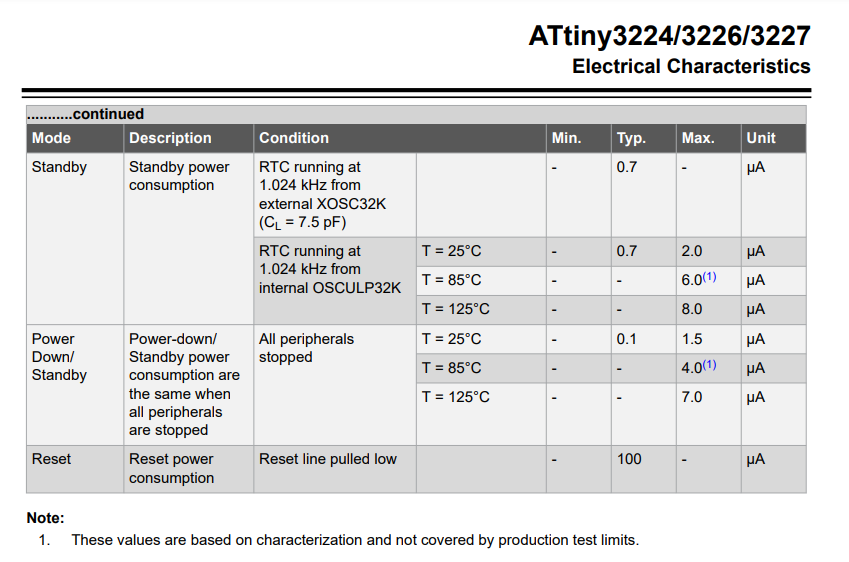
Giving it a quick look, it seems both better and cheaper. What's not to like about this thing? I guess maybe just the total dearth of tutorials regarding it? -
@ejlane Aha! Bingo! Thanks for the page reference! Looks as though attiny3226 is the same 100na in powerdown as the atmega328p:
Giving it a quick look, it seems both better and cheaper. What's not to like about this thing? I guess maybe just the total dearth of tutorials regarding it?@NeverDie Yeah, I think they are the next gen device. I believe that this batch that came out in the past ~6 months was the first production run of the '2' series devices. At least it was the first time that I had seen them available, though it wasn't something I had been actively searching for.
Should be about an identical AVR instruction set, but some of the low level stuff like registers might have changed, so it might take a bit of work to convert projects to it. I haven't done it yet to know.
-
Something to consider regarding the modules is that the maximum rated instantaneous current draw, according to the datasheet is 580ma:
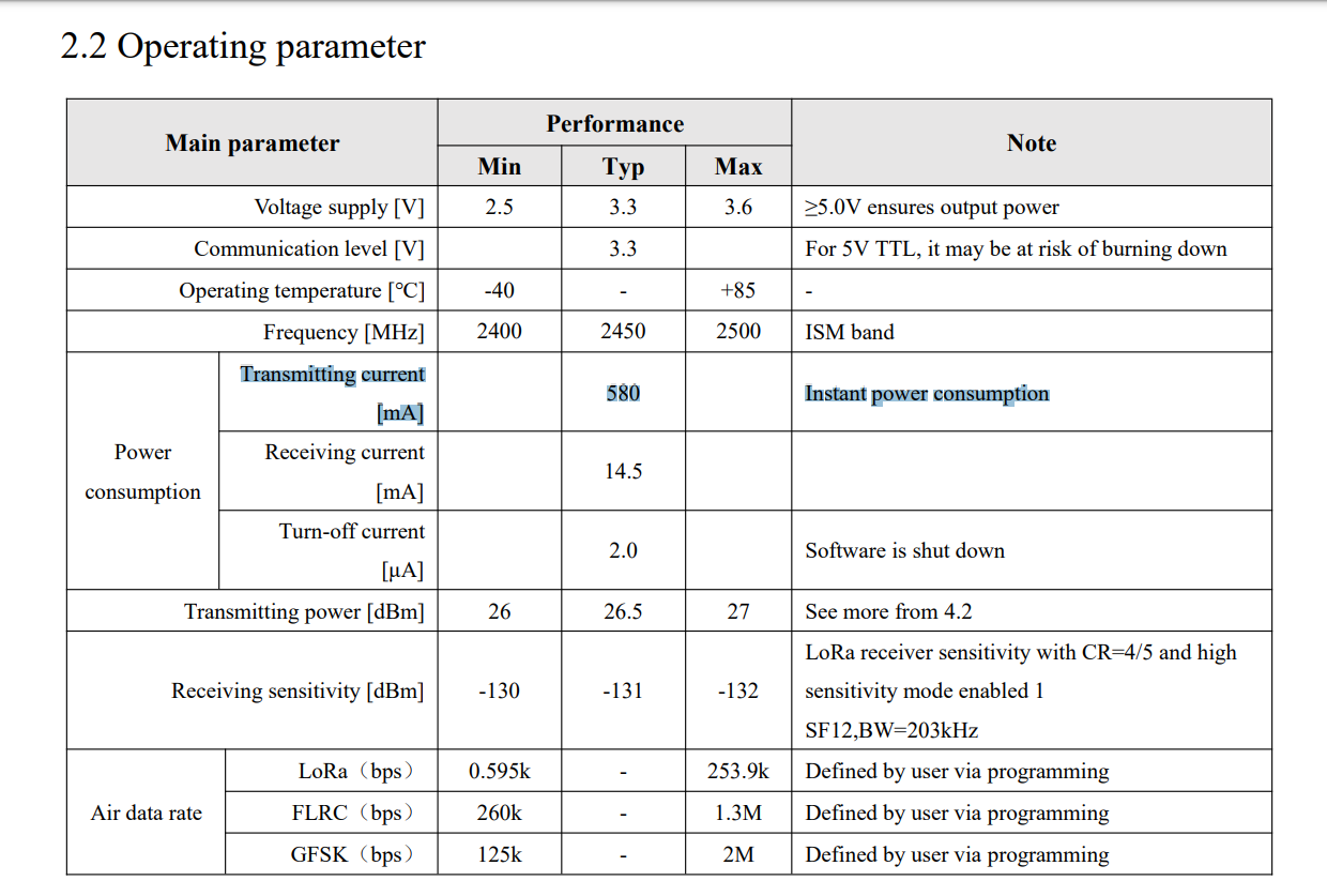
That's worthy of note because the maximum current rated for a usb 2.0 port is just 500ma. So, if you're powering it from a USB 2.0 port off your computer via an LDO, that's potential problem #1. A USB 3.0 port, on the other hand, is rated for 900ma, so that would be fine. However, if you're powering it from most FTDI connectors (which typically max out at 50ma when operating at 3.3v mode), that's still going to be a problem. In this case, powering it from a Sparkfun Beefy 3 may be a solution, as "Built upon the same foundation as our 3.3V SparkFun FTDI Basic Breakout, the Beefy 3 is equipped with an AP2112K voltage regulator making this FTDI basic breakout board capable of handling a current load of up to 600 mA!" However, that's still cutting it very close though to the 580ma that the datasheet says is required. If you're powering it by some other means, you'll want to be sure you aren't backdriving your FTDI connection, as that wouldn't be good either.My solution? I'm going to create my own custom 3.3v FTDI to UART board that can handle higher current (probably 1 amp or more) just to be sure I have enough headroom for a standalone solution. While I'm at it, I'll make sure to pick a low noise LDO....
[Edit: I think I'll go with the LT1965 LDO: https://www.mouser.com/datasheet/2/609/1965fb-1269903.pdf for it's overkill capability. Rated at 1.1a current, low noise, and big enough that it should be able to disappate heat better than some of the smaller, lower cost alternatives. That will also make it useful as a more general purpose tool. ]
-
Something to consider regarding the modules is that the maximum rated instantaneous current draw, according to the datasheet is 580ma:
That's worthy of note because the maximum current rated for a usb 2.0 port is just 500ma. So, if you're powering it from a USB 2.0 port off your computer via an LDO, that's potential problem #1. A USB 3.0 port, on the other hand, is rated for 900ma, so that would be fine. However, if you're powering it from most FTDI connectors (which typically max out at 50ma when operating at 3.3v mode), that's still going to be a problem. In this case, powering it from a Sparkfun Beefy 3 may be a solution, as "Built upon the same foundation as our 3.3V SparkFun FTDI Basic Breakout, the Beefy 3 is equipped with an AP2112K voltage regulator making this FTDI basic breakout board capable of handling a current load of up to 600 mA!" However, that's still cutting it very close though to the 580ma that the datasheet says is required. If you're powering it by some other means, you'll want to be sure you aren't backdriving your FTDI connection, as that wouldn't be good either.My solution? I'm going to create my own custom 3.3v FTDI to UART board that can handle higher current (probably 1 amp or more) just to be sure I have enough headroom for a standalone solution. While I'm at it, I'll make sure to pick a low noise LDO....
[Edit: I think I'll go with the LT1965 LDO: https://www.mouser.com/datasheet/2/609/1965fb-1269903.pdf for it's overkill capability. Rated at 1.1a current, low noise, and big enough that it should be able to disappate heat better than some of the smaller, lower cost alternatives. That will also make it useful as a more general purpose tool. ]
@NeverDie But that's only the instantaneous current needed for transmitting data over the radio. The receive current is more like what it will be doing the majority of the time. Put a beefy capacitor or two on the power line and they should handle those short little spikes.
I mean, you're not going to have a super-complicated web page on there or something. The packets being sent out will be what 1kB or something max, even serving a simple web page? According to this page: https://docs.espressif.com/projects/esp-idf/en/latest/esp32/api-guides/wifi.html#esp32-wi-fi-throughput you might get close to 80MBit/s speed. With some overhead, maybe the packet needs 10kBit, so it would only need to be on for 125uS. Even if the packets were far larger, the amount of time the radio needs to transmit is still a small fraction of the overall time. So just choose your capacitor(s) accordingly, and you'll be fine.
-
@NeverDie But that's only the instantaneous current needed for transmitting data over the radio. The receive current is more like what it will be doing the majority of the time. Put a beefy capacitor or two on the power line and they should handle those short little spikes.
I mean, you're not going to have a super-complicated web page on there or something. The packets being sent out will be what 1kB or something max, even serving a simple web page? According to this page: https://docs.espressif.com/projects/esp-idf/en/latest/esp32/api-guides/wifi.html#esp32-wi-fi-throughput you might get close to 80MBit/s speed. With some overhead, maybe the packet needs 10kBit, so it would only need to be on for 125uS. Even if the packets were far larger, the amount of time the radio needs to transmit is still a small fraction of the overall time. So just choose your capacitor(s) accordingly, and you'll be fine.
@NeverDie Oh, whoops, looks like you're probably talking about a different module? I saw the transmit number, and had been recently talking about the ESP32, which has a similar TX power number, and looks like I misread your post.
The overall point remains, but it depends on the TX time vs. the rest of the time for the overall average power consumption and the size of capacitor needed.
-
@NeverDie Oh, whoops, looks like you're probably talking about a different module? I saw the transmit number, and had been recently talking about the ESP32, which has a similar TX power number, and looks like I misread your post.
The overall point remains, but it depends on the TX time vs. the rest of the time for the overall average power consumption and the size of capacitor needed.
@ejlane Yes, good point about using a capacitor to compensate.
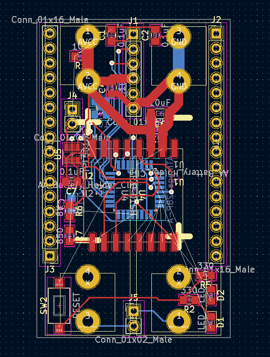
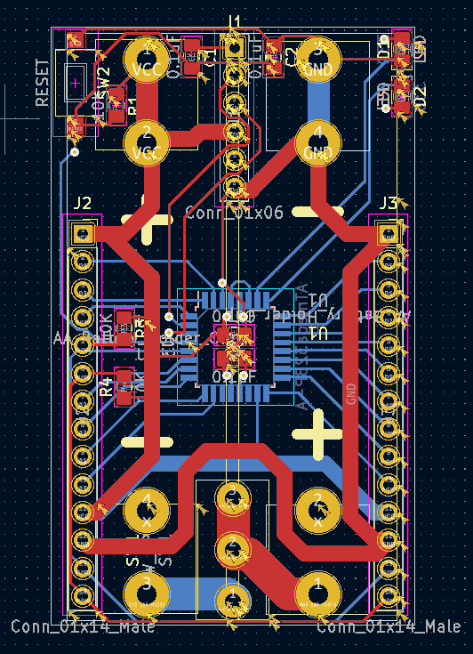
27dB Tx power is, not considering inefficiencies, nominally equal to roughly 0.5amp, so the stated 580ma is probably about right and not mostly just in-rush current. LoRa transmissions can be rather lengthy, but I suppose a sufficiently large capacitor could compensate for that as well.As it turns out I already went ahead and did a draft layout in KiCad for it:
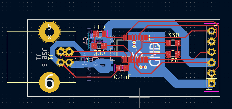
Having already invested the time, I'm going to build it. The low noise aspect LT1965 LDO might (?) still make a difference. I also like that it has a USB-B connector on it for a nice solid connection that's mechanically anchored to the PCB (none of that surface mount micro usb rubbish). I've wanted one for quite a while, and now its moment has finally come. If anyone else has interest, I can post it to openhardware.io -
Anyhow, back to the project at hand. I completed design of two different barebones mcu boards (one is just atmega328p and the other allows an Arduino pro mini to dock with it instead) that are 2xAA battery powered:
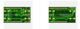
Given the wait time from a PCB fab, I went with two different designs just in case I made an error and one of them doesn't work. They both have identical test points where I can separately monitor current consumed by the mcu vs current consumed by the radio--all the better to tease apart what's really going on. Then I also have five different radio shields that fit either mcu board exactly the same:
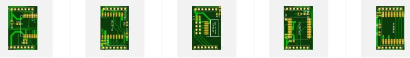
As JLPCB doesn't work on weekends, I'm going to design a few more boards and then submit them all on Sunday night. When they finally do arrive in the mail, I'll not only be better able to evaluate the E28-2G4M27S (because the new design should practically eliminate any hardware noise), but also compare the following radios against one another for their relative performance on the exact same platform: 2.4Ghz E28-2G4M27S, three different kinds of 915Mhz SX1262 LoRa, a number of different kinds of 2.4GHz nRF24L01 (all with PA and LNA to put them on the same playing field as the other radios in the round-up), a 915Mhz RFM69HW, and a 400Mhz Ra-01 LoRa. Of interest to me are what makes for a reliable "worst case" range in my home environment at different transmission power levels and if anything stands out as a clear winner in terms of energy efficiency for bits that are reliably delivered. By worst case, I mean transmitting from behind a cement footer almost 6 feet beneath grade to a second story room across the house diagonally at the point furthest from it. If transmissions can work reliably along that transmission path, then they're probably good between any other two points in the house as well. There is, for instance, no way that a bog standard nRF24L01 could deliver any packets along that path, because its transmit power is just 0dB. However, with appropriate "boosting" via PA and LNA, I think it has a chance. In comparison, I previously tested the 400Mhz LoRa along this path, and it worked without a hitch. Matter of fact it could reach a quarter mile (or better) in all directions outside the house as well using just the default parameters in the old RadioHead libraries. I'll try that test again, but this time with the new library to see if it fares any differently this time around, as well as try LoRa at 915Mhz and 2.4Ghz.
Depending on how the testing goes, I may leverage the same platform to also try out some other inexpensive radio modules that I've seen on Aliexpress that, up to now, I've lacked an easy way to comparison test. For instance, some featuring radio chips made by Texas Instruments (CC1101, CC1310, CC1352, CC1120, CC2450, CC2640, CC2650, and a whole slew of others) and some featuring radio chips made by Silicon Labs (e.g. Si4463). If you know of chips that you're keen to try, let me know and maybe I can try them for you in a way that will be meaningful because of the comparisons. I'm not expecting that big differences will emerge that aren't already known, but testing will cut through the marketing propaganda and (hopefully) reveal the truth.
Hello! It looks like you're interested in this conversation, but you don't have an account yet.
Getting fed up of having to scroll through the same posts each visit? When you register for an account, you'll always come back to exactly where you were before, and choose to be notified of new replies (either via email, or push notification). You'll also be able to save bookmarks and upvote posts to show your appreciation to other community members.
With your input, this post could be even better 💗
Register Login