Most reliable "best" radio
-
@NeverDie I thought your turnaround time was decent compared to mine. It has been taking up to 3 weeks for me to get mine from OSHpark. The last fab I ordered, I priced it out at PCBway but they were $29 versus OSHpark's $16. I do find though that within days of sending it off for fabrication, I'm making improvements to the design and kicking myself for placing the order too soon.
@alphaHotel said in Most reliable "best" radio:
I thought your turnaround time was decent compared to mine.
My latest OSH Park order was 9 days inclusive (ordered 6/20/22, delivered on 6/28/22). I find that pretty remarkable. I've read, somewhere, that the timing is at risk of your position in the panel queue; if you are early on the panel, then it is slower. There is a “super swift” service from OSH for a charge. Free-shipping moves faster than I can, so I can wait. The price can't be beat and the quality is great (except for the errors that I make!!!)
@NeverDie
The silkscreen markings for the AA mount posts on your Test Platform V001 are on the right side for me. Mine arrived last week! Sure, the markings are on the reverse side, but once the batteries are installed, that side is invisible. I’m still fretting the moment when I need to solder the Atmega 328P chip.To follow-up on earlier posts: the speed of delivery from China has dramatically improved. Most of the orders I’ve place in early June have arrived. Even the hard-to-get Atmega 328P chips have arrived so I don’t have to desolder my old Nano’s or ProMini’s. And the Chinese packaging is efficient - less trash for my conscience. Digi-Key leaves me wondering how such little can arrive in a box that is so big. But... Digi-Key is so fast.
-
I'm finding that some of the basic UART example programs in Segger Embedded System's IDE no longer even compile for the nRF52-DK without encountering obscure errors that, judging from some youtube videos, didn't exist a year ago. Did Segger fail to maintain their example code during covid? I couldn't get to the bottom of it, so I'm punting on SES and will be switching to gcc, which I hope won't have the same issues. Fingers crossed.Looks as though I'll be sticking with SES a bit longer, because it does contain at least one example shell for the nRF52805, and as long as I can hollow out and fill that shell with bare metal code, then (so far) it all seems to compile and upload and the code works on the nRF52805. At the moment I've confirmed that the bare metal UART code I put together from just the datasheet alone (which has far more ambiguity in it than I remember it having) is now properly working inside the nRF52805, which was (is?) probably the hardest thing to get going, but now that it's in place (for debugging purposes) I feel more comfortable moving ahead like this. One thing I do like about SES is that compared to GCC the compile and upload cycle happens very, very quickly. That alone may not by itself be a deciding factor in what to toolchain to choose, but it is a nice luxury that I truly enjoy.
Next up: getting some bare metal proprietary radio code to work on the nRF52805. Ignoring the PCB antenna, the rest of the module looks as though it is smaller than the size of a dime! I don't yet fully grasp the details of how Nordic crippled it, so I hope I won't be tripping across any nasty gotcha's. ;-) Apparently one of the benefits of the crippling it is that it is more power efficient (as, for instance, it has less memory to retain while sleeping). Compared to its siblings, it has "only" 24KB of RAM and 192K of flash, but that is nonetheless hugely more than what the atmega328p has, so from that perspective it should have more than enough for doing most Arduino-type things. It's biggest cramping limitation seems to be its very small number of GPIO pins (technically 10 pins, but really more like 9 pins since one of the ten pins serves as a RESET pin).
-
I have nRF52805's and nRF52832's talking to one another using the proprietary radio, and I obviously have nRF2401's talking to one another, but getting the two groups to talk to each other? It's not obvious how to do that: Enhanced Shockburst of the nRF24L01 has a weird 9 bit section called PCN in the middle of it, and it's not clear how to get an nRF2 to receive that kind of oddball frame without rejecting it. That said, I think it probably can be done, but it would maybe turn into a long detour that I'd rather not take right now. It turns out there does still exist regular, non-enhanced Shockburst which the nRF24L01 can still use and which doesn't have the oddball 9-bit PCN, but then the maximum transmit speed of an nRF24L01 is limited to 1mbps. That's no good, because I want to use the faster 2mbps, which is almost the entire allure of using Nordic chips instead of something else. So, in the interest of not getting detoured, when it comes to 2.4Ghz, I guess I'll just plow ahead using just nRF52 chips and see how low I can drive the energy consumption on an nRF52805 and still be able to wake it up with a radio packet. Since a lot of the energy goes toward just waking up the radio and getting it up to speed before it can receive anything, it may yet turn out that accepting a 1mbps on-air bitrate won't be too big a compromise, but I'd rather make that decision based on actual measurements rather than guesswork alone.
Between now and then I need to confirm that the BC805M has functioning DCDC circuitry in it, and I also need to measure the sleep current on the BC805M to make sure it won't be worse than expected with the integrated RTC running, which I'd like to use instead of a TPL5111 if the current drain will allow. If I need little to no external circuitry, then, aside from batteries, this whole thing could literally fit on a dime.
By the way, and unrelated to all that I just wrote, I finally came across a nice articulate introduction to the stm32 and its toolchain:
https://www.youtube.com/watch?v=ftjQ6YelAXE
He had already done one introductory series, but now he's re-doing it to make it current and more polished. So far I like his approach of starting with the simplest possible thing and then building up from there. STM has some pretty cool looking tools that I haven't seen before in other toolchains. For instance, one of the tools has Node Red built right into it! In addition to that, there's a debugging tool that not only allows you to inspect the value of a variable, but plot its value over time. Like I said, nifty cool stuff. That said, the whole thing looks like a surprisingly PITA to install, which is where this video series comes to the rescue by holding your hand through all that. If you ask me, STM should add this guy to their payroll, because he clearly "get's it" far more than the ST product managers do. For instance, he shows that if you follow the ST installation instructions to a T, then you run into dead links that have evidently gone stale. So, he walks you through what the instructions should have been to avoid that.
@NeverDie Just checking in. I've received lots of different radios and built two of your bare-bones kits. Soldering the Atmega328P chips were easier than I thought – first time ever on pins that small. My MM showed many, many solder bridges existed. Solder-wick helped fix that. Hope I didn’t burn the chip.
Before I start running tests on the different radio’s as you have, I’ve been getting a GPS functioning which has been fun. After collecting data around the perimeter of our small property, I figured out how to do a XYZ 3-D plot in Excel – not easy.
In the GPS process I’ve been watching this video (https://www.youtube.com/watch?v=gtM832Z0ujE&t=219s ) and he has a conclusion that you might be interested in: locating the transmitting radio (nrf24L01) close to the MCU was limiting the packet/per/second performance, and limiting range. With this in mind, I hope to test your radio carrier boards on a Dupont wire extension raising it off the bare-bones board. Then test with and without and see how it does. Again, I’m hoping all that wire doesn’t inadvertently create unwanted antennae interference.
But, obviously, I’m on the slow road still.
-
@NeverDie Just checking in. I've received lots of different radios and built two of your bare-bones kits. Soldering the Atmega328P chips were easier than I thought – first time ever on pins that small. My MM showed many, many solder bridges existed. Solder-wick helped fix that. Hope I didn’t burn the chip.
Before I start running tests on the different radio’s as you have, I’ve been getting a GPS functioning which has been fun. After collecting data around the perimeter of our small property, I figured out how to do a XYZ 3-D plot in Excel – not easy.
In the GPS process I’ve been watching this video (https://www.youtube.com/watch?v=gtM832Z0ujE&t=219s ) and he has a conclusion that you might be interested in: locating the transmitting radio (nrf24L01) close to the MCU was limiting the packet/per/second performance, and limiting range. With this in mind, I hope to test your radio carrier boards on a Dupont wire extension raising it off the bare-bones board. Then test with and without and see how it does. Again, I’m hoping all that wire doesn’t inadvertently create unwanted antennae interference.
But, obviously, I’m on the slow road still.
@Larson said in Most reliable "best" radio:
@NeverDie Just checking in. I've received lots of different radios and built two of your bare-bones kits. Soldering the Atmega328P chips were easier than I thought – first time ever on pins that small. My MM showed many, many solder bridges existed. Solder-wick helped fix that. Hope I didn’t burn the chip.
When I encounter hard-to-rid solder bridges, I ladle on gobs of that resin that I linked for you earlier on amazon. Use tons of the stuff, such that the whole area is submerged in it. Then when you hit the area with a hot soldering iron, the solder bridges all magically separate like Moses parting the Red Sea. Not all resins are equally effective in that regard, which is why I pointed you to a resin that seems to work really well. There are also some "hoof" soldering tips that help pull off excess solder onto the tip via capillary action, which you can then wipe off onto brass wool or a sponge. Those tips are a definite nice-to-have, but not strictly necessary. With the right resin, the resin will do most of the work for you. If you're still having trouble, then you may want to raise the heat on your soldering iron. When I want to deliberately create solder bridges, I lower the temperature on my soldering iron to make it closer to the melting point.
-
I'm using my "proto-board" to prototype a basic nRF52805:
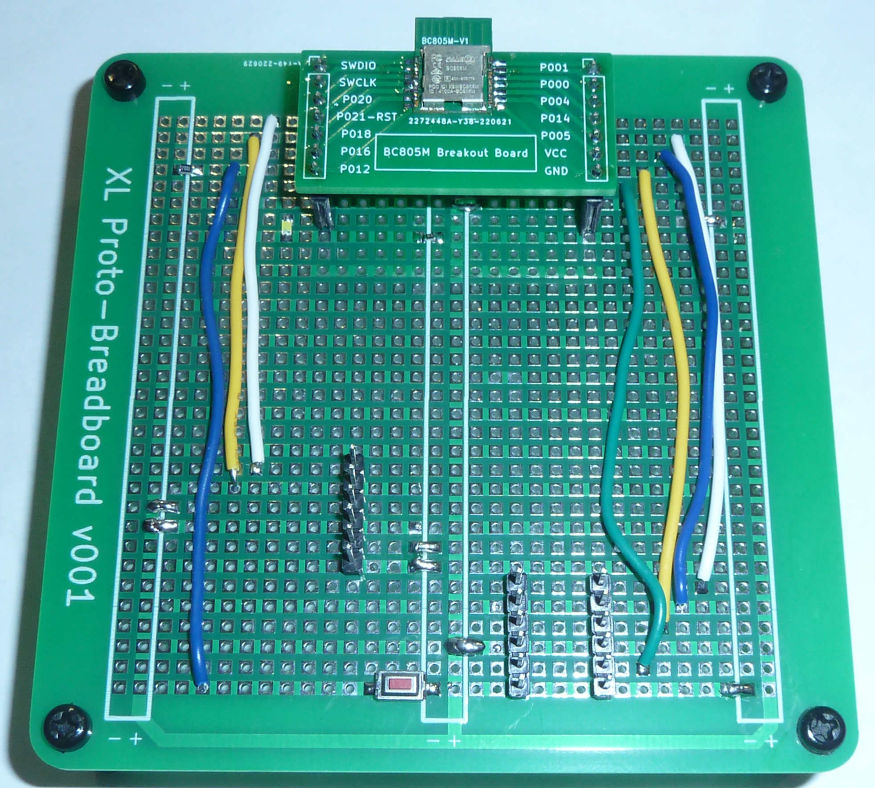
It's working fine, except for the reset pin. Apparently Nordic has introduced new "advanced protection" that's preventing me from assigning and enabling P0.21 to be the RESET without some sort of complicated obscure sequence to disable the advanced protection. -
@Larson said in Most reliable "best" radio:
@NeverDie Just checking in. I've received lots of different radios and built two of your bare-bones kits. Soldering the Atmega328P chips were easier than I thought – first time ever on pins that small. My MM showed many, many solder bridges existed. Solder-wick helped fix that. Hope I didn’t burn the chip.
When I encounter hard-to-rid solder bridges, I ladle on gobs of that resin that I linked for you earlier on amazon. Use tons of the stuff, such that the whole area is submerged in it. Then when you hit the area with a hot soldering iron, the solder bridges all magically separate like Moses parting the Red Sea. Not all resins are equally effective in that regard, which is why I pointed you to a resin that seems to work really well. There are also some "hoof" soldering tips that help pull off excess solder onto the tip via capillary action, which you can then wipe off onto brass wool or a sponge. Those tips are a definite nice-to-have, but not strictly necessary. With the right resin, the resin will do most of the work for you. If you're still having trouble, then you may want to raise the heat on your soldering iron. When I want to deliberately create solder bridges, I lower the temperature on my soldering iron to make it closer to the melting point.
@NeverDie Thanks for the tip. I went as far as dipping my solder wick in my new SRA Flus #135 (yes, your recommendation; thank you again). That may have been the trick because ... it worked! Actually, I didn’t dip it but smooged the stuff onto the wick using a toothpick as a trowel. Yea, it was a mess afterwards. I used a foil tray as an alcohol bath before cleaning with a toothbrush.
My problem today is bootloading the brand new 328's with my old USBASP. The IDE says something about “cannot set SCK period” and then “initialization failed”. I’ve been here before and it just takes time to relearn. I made ReadMe notes but I can’t find them. I’ll try again tomorrow.
-
@NeverDie Thanks for the tip. I went as far as dipping my solder wick in my new SRA Flus #135 (yes, your recommendation; thank you again). That may have been the trick because ... it worked! Actually, I didn’t dip it but smooged the stuff onto the wick using a toothpick as a trowel. Yea, it was a mess afterwards. I used a foil tray as an alcohol bath before cleaning with a toothbrush.
My problem today is bootloading the brand new 328's with my old USBASP. The IDE says something about “cannot set SCK period” and then “initialization failed”. I’ve been here before and it just takes time to relearn. I made ReadMe notes but I can’t find them. I’ll try again tomorrow.
@Larson I use an AVR Dragon. I don't think they are even manufactured anymore, but it still works and it makes burning bootloaders and setting fuses a snap from within what is now called Microchip Studio (what used to be called Atmel studio). It's also a "high voltage" programmer to resurrect chips that low voltage programmers cannot. It turns out I've never had a reason to use the high voltage feature, but it was a selling point at the time.
Anyhow, I meantion it because if you can find a programmer that does dance with Microchip Studio, it's a fairly easy interface to learn and to use. You just go to menu Tools....Device Programming... and it's all right there. Microchip Studio is free so if you want to preview what it might look like, just download it and give it a squiz. I don't actually use Microchip Studio for anything other than just this particular feature
-
@Larson I use an AVR Dragon. I don't think they are even manufactured anymore, but it still works and it makes burning bootloaders and setting fuses a snap from within what is now called Microchip Studio (what used to be called Atmel studio). It's also a "high voltage" programmer to resurrect chips that low voltage programmers cannot. It turns out I've never had a reason to use the high voltage feature, but it was a selling point at the time.
Anyhow, I meantion it because if you can find a programmer that does dance with Microchip Studio, it's a fairly easy interface to learn and to use. You just go to menu Tools....Device Programming... and it's all right there. Microchip Studio is free so if you want to preview what it might look like, just download it and give it a squiz. I don't actually use Microchip Studio for anything other than just this particular feature
@NeverDie said in Most reliable "best" radio:
Anyhow, I meantion it because if you can find a programmer that does dance with Microchip Studio, it's a fairly easy interface to learn and to use. You just go to menu Tools....Device Programming... and it's all right there. Microchip Studio is free so if you want to preview what it might look like, just download it and give it a squiz. I don't actually use Microchip Studio for anything other than just this particular feature
Thanks for another tip/reminder. I still have the Atmel Studio 7, Microchip Studio predecessor, loaded and I think that played a role for me in the past in this hurdle – you reminded me of that. I’ll give it another go. I remember the strength of AS7 was that one could debug code (see registers) a command at a time – pretty cool.
-
@NeverDie Thanks for the tip. I went as far as dipping my solder wick in my new SRA Flus #135 (yes, your recommendation; thank you again). That may have been the trick because ... it worked! Actually, I didn’t dip it but smooged the stuff onto the wick using a toothpick as a trowel. Yea, it was a mess afterwards. I used a foil tray as an alcohol bath before cleaning with a toothbrush.
My problem today is bootloading the brand new 328's with my old USBASP. The IDE says something about “cannot set SCK period” and then “initialization failed”. I’ve been here before and it just takes time to relearn. I made ReadMe notes but I can’t find them. I’ll try again tomorrow.
@Larson said in Most reliable "best" radio:
My problem today is bootloading the brand new 328's with my old USBASP. The IDE says something about “cannot set SCK period” and then “initialization failed”.
If you have a second USBASP or an Arduino of some sore lying around, you could try to update the firmware on the USBASP. I recommend this edition, latest release and a Google search for "how to update usbasp firmware". You may see that with release v1.06 of that repository, there was an improvement that "Includes automatic SCK slowing".
Of course, the problem may be more rudimentary. Can you read the fuses? Are they set to use an external oscillator that doesn't exist?
-
@Larson said in Most reliable "best" radio:
My problem today is bootloading the brand new 328's with my old USBASP. The IDE says something about “cannot set SCK period” and then “initialization failed”.
If you have a second USBASP or an Arduino of some sore lying around, you could try to update the firmware on the USBASP. I recommend this edition, latest release and a Google search for "how to update usbasp firmware". You may see that with release v1.06 of that repository, there was an improvement that "Includes automatic SCK slowing".
Of course, the problem may be more rudimentary. Can you read the fuses? Are they set to use an external oscillator that doesn't exist?
@alphaHotel I'll try the firmware update. Thanks. I suspect my problem is the SCK speed. I get immediate failure. I don't think I can reach the fuses if the 'target' chip doesn't have a bootloader. Do I have that wrong? The wierd thing is that I used my USBasp to bootload an extra Nano I have on hand. That worked fine. On the bare bones board, I've double/triple checked the connections and I've rechecked the 328 chip for solder bridges & solid connections with pins. I have downloaded your recommended link. The 2011-05-28 Thomas Fischl Readme.txt file looks complicated. I'll see if I can manage that. Thanks again.
-
BTW, I had previously failed to notice that an nRF52840 can be powered from up to 5.5v because it has a built-in buck regulator designed to manage that higher input voltage. That might make a 3 or possibly even 4 battery configuration, depending on battery chemistry, pretty compelling, because it would extend battery life so much longer.
-
@Larson said in Most reliable "best" radio:
My problem today is bootloading the brand new 328's with my old USBASP. The IDE says something about “cannot set SCK period” and then “initialization failed”.
If you have a second USBASP or an Arduino of some sore lying around, you could try to update the firmware on the USBASP. I recommend this edition, latest release and a Google search for "how to update usbasp firmware". You may see that with release v1.06 of that repository, there was an improvement that "Includes automatic SCK slowing".
Of course, the problem may be more rudimentary. Can you read the fuses? Are they set to use an external oscillator that doesn't exist?
@alphaHotel Still working on getting my USBASP reprogrammed. After googling I found this site: https://www.electronics-lab.com/project/usbasp-firmware-update-guide. That program says to create a new programmer; I used a Nano and uploaded the ArduinoISP successfully. Next I combine the avrdude.conf, avrdude.exe, and the update hex file in one file as suggested. I used your latest release link to find the update hex file to be main.hex for the Atmega8 that lives on my USBASP. The readme files in your link lead me to that conclusion.
After connecting everything together I enter “avrdude -C avrdude.conf -P COM9 -p m8 -c avrisp -b 19200 -U flash:w:usbasp.atmega8.main.hex:I” in the windows command line.I get these errors:
avrdude: error at avrdude.conf:1133: programmer type jtagice3_updi not found
avrdude: error reading system wide configuration file "avrdude.conf"I found jtagice3 in the config file to be a defined programmer. I feel that I’m close. Any ideas? I continue to work on it.
-
@alphaHotel I'll try the firmware update. Thanks. I suspect my problem is the SCK speed. I get immediate failure. I don't think I can reach the fuses if the 'target' chip doesn't have a bootloader. Do I have that wrong? The wierd thing is that I used my USBasp to bootload an extra Nano I have on hand. That worked fine. On the bare bones board, I've double/triple checked the connections and I've rechecked the 328 chip for solder bridges & solid connections with pins. I have downloaded your recommended link. The 2011-05-28 Thomas Fischl Readme.txt file looks complicated. I'll see if I can manage that. Thanks again.
@Larson said in Most reliable "best" radio:
I don't think I can reach the fuses if the 'target' chip doesn't have a bootloader. Do I have that wrong?
You can reach (read/write) the fuses with a USBASP regardless of whether there is a bootloader. If you have any troubles, shoot me a message in the chat or start a new thread somewhere and I'll help you through it.
-
@Larson said in Most reliable "best" radio:
I don't think I can reach the fuses if the 'target' chip doesn't have a bootloader. Do I have that wrong?
You can reach (read/write) the fuses with a USBASP regardless of whether there is a bootloader. If you have any troubles, shoot me a message in the chat or start a new thread somewhere and I'll help you through it.
@alphaHotel Chat sent. My apologies to NeverDie for the distractions to a very fine thread.
-
Reporting back on Piezo buzzers discussed earlier in this thread: I just now tested out a ceramic disk piezo, and, indeed, it appears they more or less require a resonate cavity of some kind to get loud enough. Putting a 3.8KHz square wave into one that already has a resonate cavity to go with it, it appears to consume about 400ua at 3v and around 260ua at 1.8v. Interestingly, it appears you can identify the frequency of maximum loudness by selecting a frequency that gives rise to the maximum current draw. A steady tone sounds like a hearing test though, so for a more pleasant effect, I guess you have to dial-in some creative frequencies.
Anyhow, despite the cheap price for ceramic disks, I don't feel like designing a suitable resonate cavity for one, so I guess I'll look more into the premade surface mount buzzers that have resonate cavities already built into their modules.
I had thought that I wouldn't need a particularly loud buzzer, and maybe that's still the case, but since I will be putting these into sealed plastic boxes as a locator beacon, I guess maybe the louder the better in terms of finding it by ear. The trade-off is that louder mostly seems to also mean bigger.
The premade buzzers fall into two camps: actively driven by some kind of built-in circuit vs. externally driven. Since the above initial test appears to indicate that current drain won't be much, I'm leaning toward driving it "externally" with an MCU pin so that I can make R2D2 sounds if I want to. Well, I'm joking about R2D2, but I would much prefer something that doesn't sound like a hearing test.
BTW, I had thought that changing the duty cycle on the square wave used to drive the piezo would change the volume, but in the tests I performed so far, the duty cycle length actually seems to have almost no effect.
-
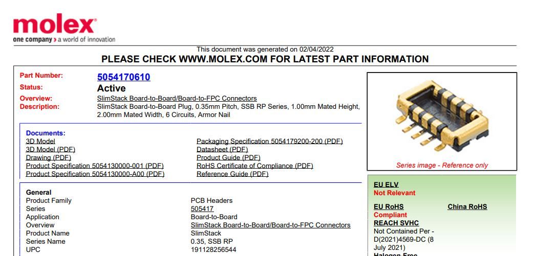
Reporting back: I finally found a name for some "press-fit" board-to-board connects: Molex slimstack.
For instance, it could maybe be used for connecting a "compute module" to a backplane. Pitch is just 0.35mm, and they come in all sizes from 6 pins up to 60 pins:
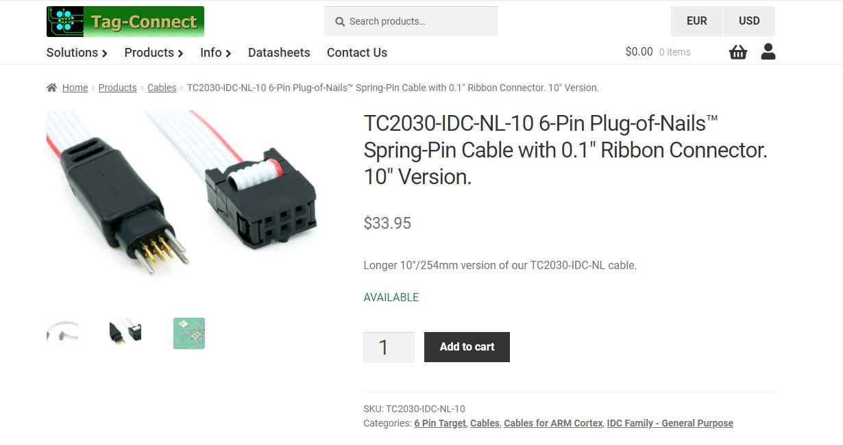
On the other hand, for a temporary programming connection, the 6 pin tag-connect might be a good idea:
Or you could possibly use a pogo-pin clip:
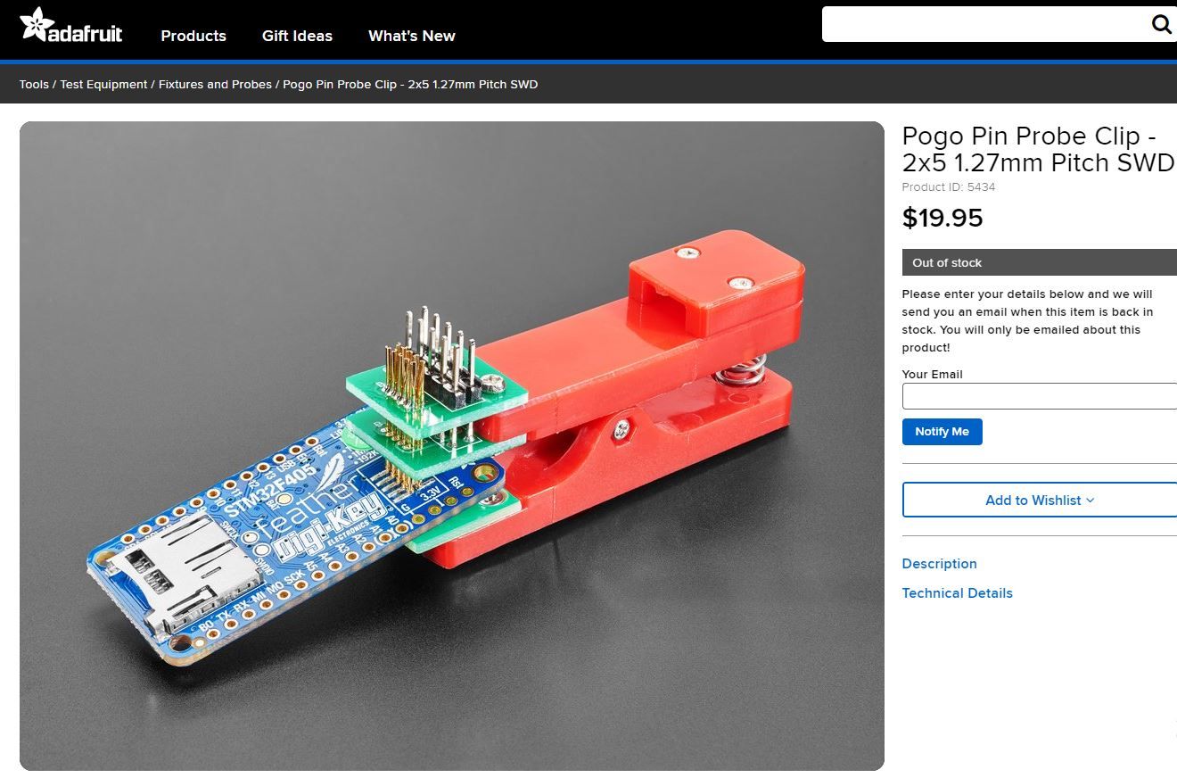
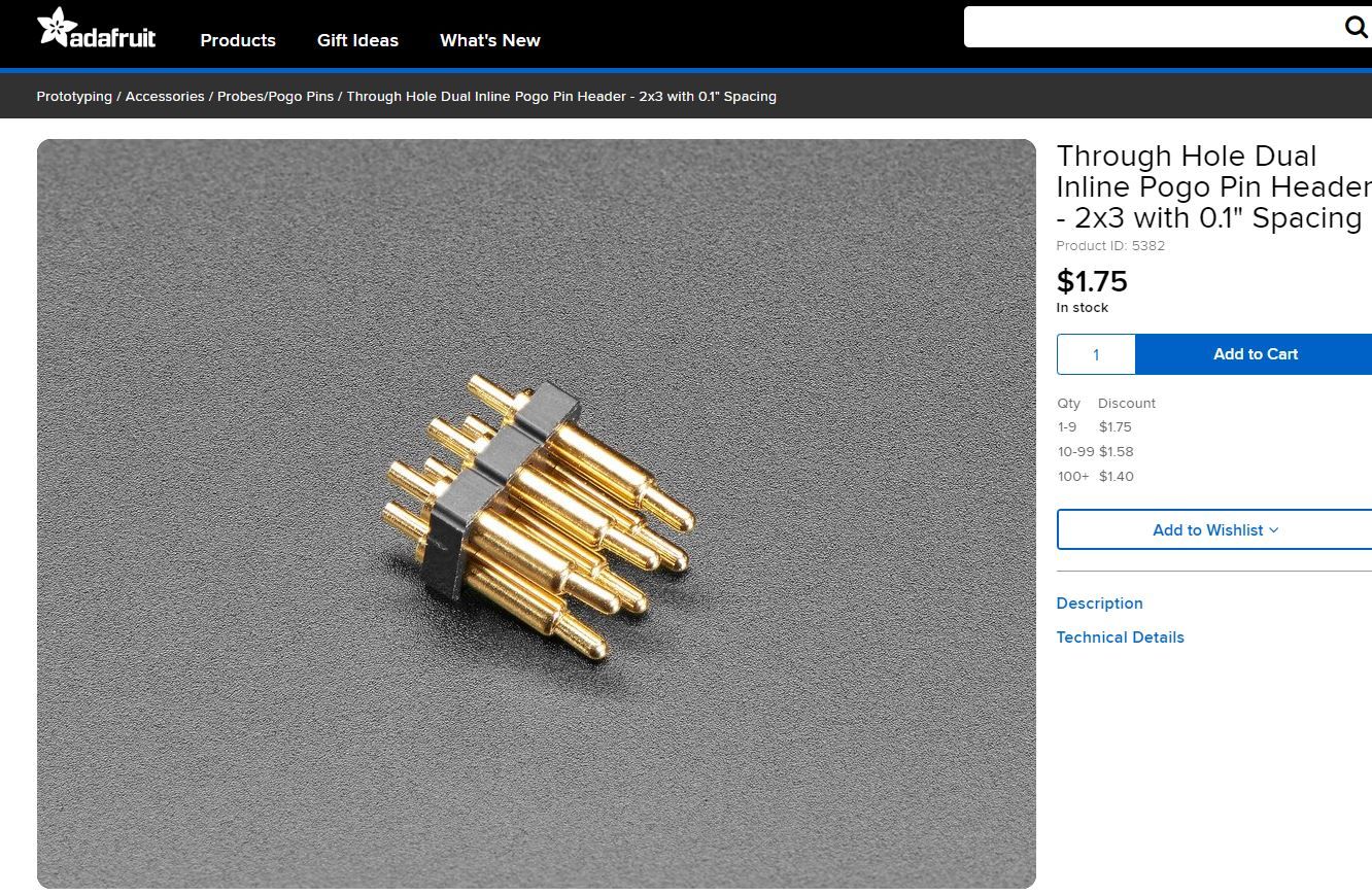
or possibly DIY your own using an inexpensive pogo pin header:
For that matter, with a few registration holes and a toggle clamp, it looks to me like you could have a darn good connection for either one-off programming or for more extended debugging:
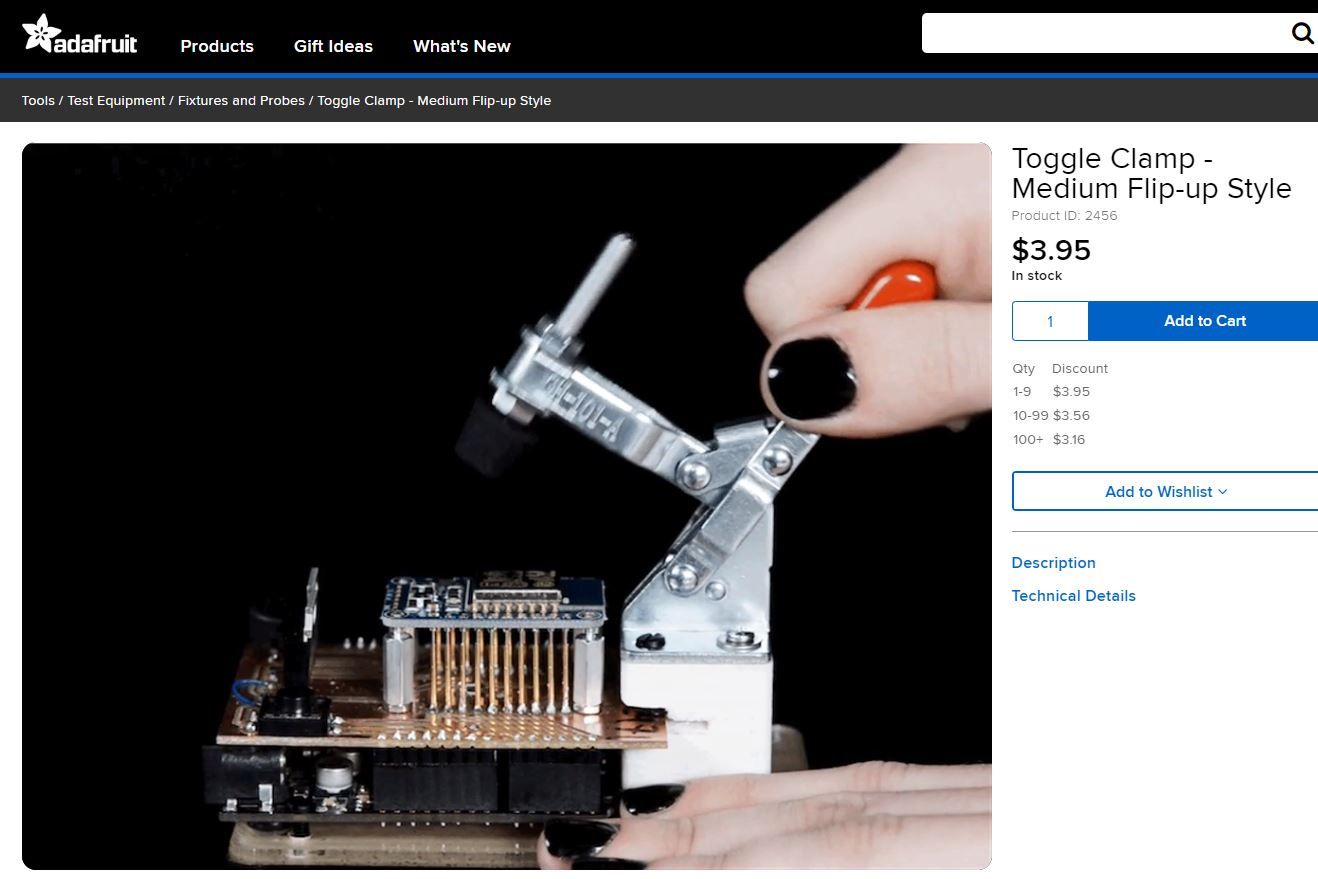
I think I may move in that direction, because then you can spread out your pogo pin pads and fit them wherever there's extra a little extra space on your PCB rather than having to bunch them all together, as in the case of the other solutions. In that sense, I suppose it's more or less a conventional custom-built bed-of-nails. -
Reporting back: I finally found a name for some "press-fit" board-to-board connects: Molex slimstack.
For instance, it could maybe be used for connecting a "compute module" to a backplane. Pitch is just 0.35mm, and they come in all sizes from 6 pins up to 60 pins:
On the other hand, for a temporary programming connection, the 6 pin tag-connect might be a good idea:
Or you could possibly use a pogo-pin clip:
or possibly DIY your own using an inexpensive pogo pin header:
For that matter, with a few registration holes and a toggle clamp, it looks to me like you could have a darn good connection for either one-off programming or for more extended debugging:
I think I may move in that direction, because then you can spread out your pogo pin pads and fit them wherever there's extra a little extra space on your PCB rather than having to bunch them all together, as in the case of the other solutions. In that sense, I suppose it's more or less a conventional custom-built bed-of-nails.@NeverDie said in Most reliable "best" radio:
I suppose it's more or less a conventional custom-built bed-of-nails.
:joy: :sunglasses:
-
@NeverDie said in Most reliable "best" radio:
I suppose it's more or less a conventional custom-built bed-of-nails.
:joy: :sunglasses:
Unfortunately, it also looks like it's the most work. I tried the picoblade on Version 1.0 of the Barebones, but I found that although picoblade makes the connection easily, the disconnection process is hard because it locks into place when you plug into it. So, for small projects, I'm looking into JST-SH connections, which have 1.0mm pitch and maybe (?) don't lock as well, which in this instance would be a good thing. I found some on amazon:
https://www.amazon.com/dp/B01DUC1M2O?psc=1&ref=ppx_yo2ov_dt_b_product_details
but the sockets are vertical. For right-angle sockets, I may may have to order from Aliexpress, because even Mouser just doesn't seem to stock them.I was faced with this same problem previously when I did this project: https://www.openhardware.io/view/510/Multi-Sensor-TempHumidityPIR-LeakMagnetLightAccel
My "solution" at the time was, in future versions, to use a micro-usb connector, which indeed was much smaller, but there was nearly universal pushback on that from people saying that anything which looks like a micro-usb connector would be mistaken for an actual USB connector, and at some point end-users would hook it up wrongly on that assumption and basically destroy the system with 5 volts. Thinking about it now, that grim outcome could be avoided by the addition of just a single diode, but then again that's yet another extra part and more board real estate.
Hello! It looks like you're interested in this conversation, but you don't have an account yet.
Getting fed up of having to scroll through the same posts each visit? When you register for an account, you'll always come back to exactly where you were before, and choose to be notified of new replies (either via email, or push notification). You'll also be able to save bookmarks and upvote posts to show your appreciation to other community members.
With your input, this post could be even better 💗
Register Login