My final Gateway version

-
My production Gateway is still on a breadboard with a normal NRF24L01+ radio - so not the long range. After 11 years it's time to get rid of that breadboard setup- as it's collecting dust - and make a final PCB for it, so that I can put it in a decent housing. Also a good moment to upgrade from MySensors 2.0.0 to the latest release as I haven't upgraded that Gateway for years.
My plan is to power the gateway from the barrel jack on the Arduino UNO and I also want to replace that normal NRF24L01 with a PAN LNA version. Now I know that extending the range consumes a lot of power. That's why I wanna power the Arduino from the power jack as it can handle 2 Amps. And then use a buck converter that grabs it's power from the VIN pin on the Arduino, to lower the voltage to 3.3V for the radio.
Well that is the plan at least. The official documentation says that you can provide power through the barrel and use the USB.
Here's the schematic for my Uno shield
:
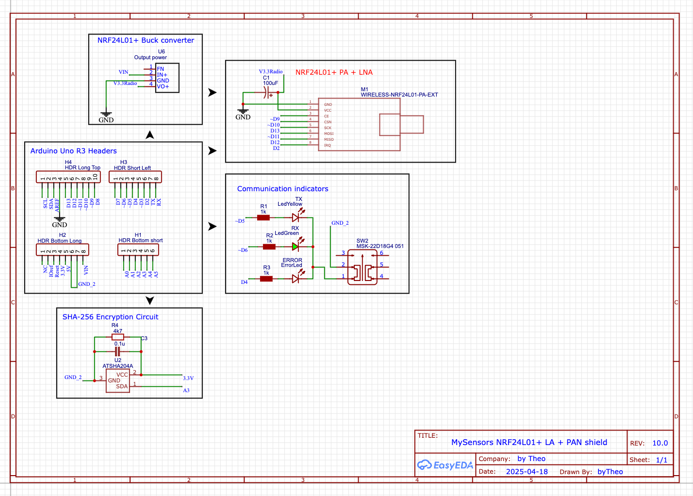
My question is: How much current does the NRF24L01 PAN LNA draw when set to RF24_PA_HIGH? Question answered 13 mA at max strength.
For now it remains Work In Progress
Edit 1:
I had this idea already over 11 years ago, but at the time I didn't have enough knowledge and skills. Then later when I had learned those I didn't have the time :).The idea is to mount all components - including the NRF24L01+ PA LNA breakout on the underside of the Uno shield. There's a crazy amount of unused surface space on the Uno so in theorie it should work. I wanted to try it out so I could come up with a very compact design.
There's one catch though. If I would ground plate the whole shield I would create a cage of Farraday - if that is the Engish term - so I only ground plated the parts where my power regulation and encryption parts are. Nothing near the radio. Not sure if it would influence the NRF or the Arduino, but better safe than sorry.
So Today while it was snowing outside, I mocked up an Arduino Uno and my shield in Free Cad - I'm using 14.8 mm header pins so that should be around 15.6 mm spacing between the boards.
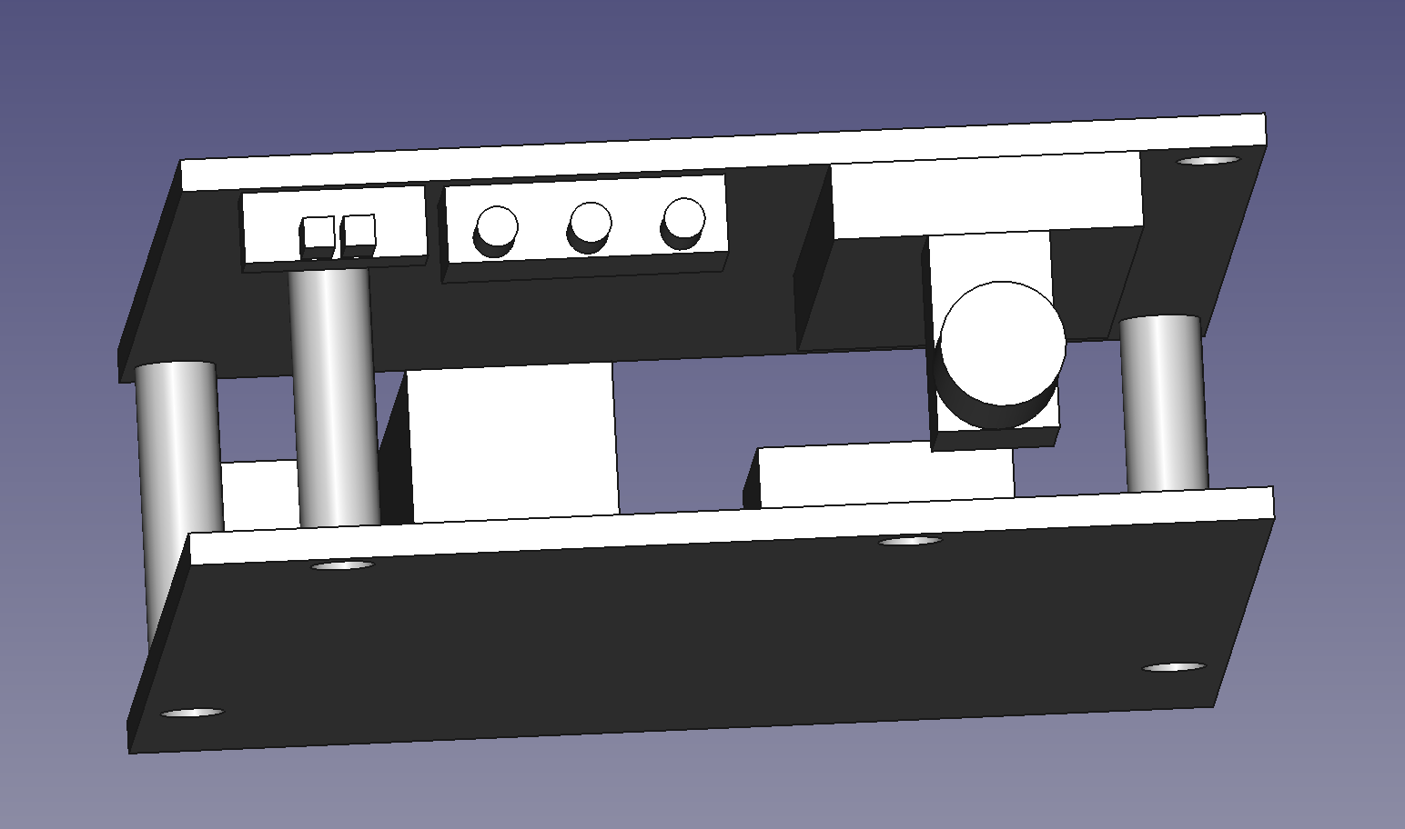
This is how the front looks, with the shield mounted on top of the Arduino Uno. The spacers will be 3d printed. The two rectangles on the top left are the positions of a slide switch. I use it to turn off the led indicators, as 99.9% of the time you don't need them. But for 0.1% the time I'm happy that they are their.
On the right of the sliding switch there are three 2 mm Leds and on the right of those there's the RP SMA connector of the NRF breakout board.
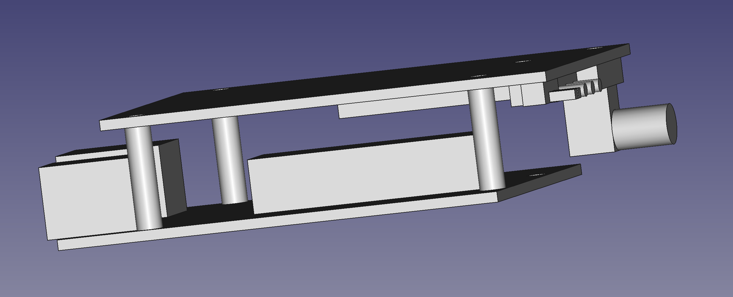
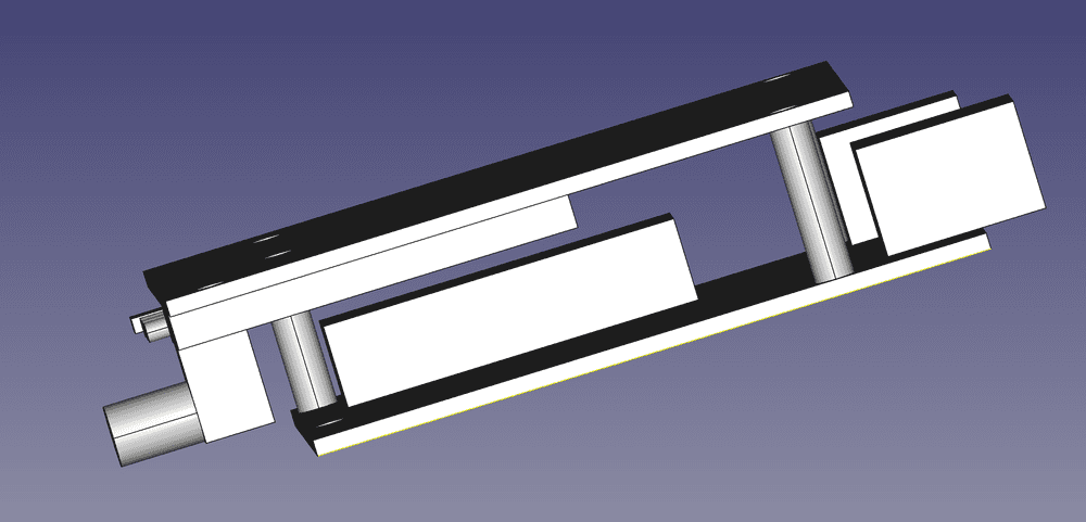
This is a side view there's plenty enough space between the shields.
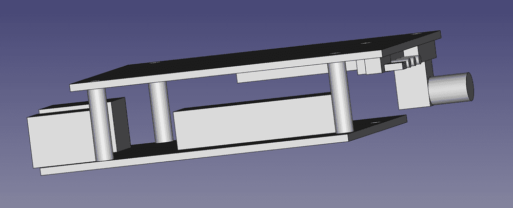
And here's the other side view. With the board thickness added it will be around 18.2 mm thick - that is without the pins of the trough hole components. But I'm confident I can keep the height of the case around or a bit above 250 mm - 1 inch.
The compacter I can get it the more happier I will be, because I'm planning on mounting all my Home Automation stuff in a server rack so that I can all hook it up to a decent UPS.
Now I have to wait for my PCB to arrive. I already discovered my screw holes are a bit off, but I fixed it. So I need to order a revision. But first I will wait for the one I ordered to arrive, so I can check if I got the pin header spacing's correct.
Update: I received the pcb's a long time ago. But I lacked time to get to work on them. So this weekend I soldered one and it's working fine. Although I need to lower the input voltage. Right now it's 12V but that's the max of the AMS1117. And it gets really warm.
I did make some discoveries
- VIN provides 5Vwhen you power the Arduino from USB. Which I didn't know. But that is good, so I can test the gateway in my current setup.
- The indicators from advanced builts on the MySensors main website work also on a Node. Which of course makes sense. But in my mind that would only work for Gateways. No idea why I had that in mind.
- with a separate LDO you can easily use max strength on a longe range NRF Radio. Even with a 100Uf capacitor.
-
@mfalkvidd Than I'll order a first prototype if this version. I might even swap the buck converter for an AMS11173V. I always thought it would draw much more current when sending.
-
Added some 3d sketches so you can see what I'm trying to accomplish. Unless ofc someone will tell me this is a bad idea
-
Added an update.
-
Just a question, maybe @mfalkvidd knows. I turned off MyDebug in a test Gateway and it seems to work. I think it makes sense but I wanted to check. Because the gateway will become faster if the additional debug isn't needed. It saves a log entry per message send/received.
But as I discovered, if i turn off debug the cap on my radio isn't good anymore. It's 100uf tantalum smd cap. When I turn the debug off, nodes have a hard time connecting to the gateway with a lot of errors.
So question number 2, is a 100uf cap good enough for a NRF24L01+ PA LNA? I might investigate any further after Eastern weekend. For now I keep it as a 2nd Gateway and keep testing it. As I don't have the time now to solve issues when I use it as a production Gateway.
Thanx
ps. I guess you'll miss some additional logging info in you're Home Automation system. But is it really needed?
-
Since it works with my PA + LNA antenna on High PA Level, I've decided to take it in production. I've kept my old Gateway just in case. Photo's will follow soon.
PA Level Max might work if you provided a power supply on the DC barrel input. But I will test it later as the Uno requires 7.5V and I'm not sure if my voltage regulator will become hot like it did with a 12V power supply. For Now I'll let the current setup run for a couple of days.
-
I had turned off debug on my MQTT gateway (RPi zero 2 w) and I had a similar experience. I didn't even consider the problem was on the radio.
I did this because messages weren't being received by the MQTT broker. Taking out DEBUG made it worse. subsequently, I put wait (not delay) statements after each send. It's all working well for me.
For those that don't know, delay is blocking, that is, nothing gets processed during the delay. wait, (a MySensors library function?) is non-blocking. That is, MySensors will continue to process outgoing and incoming messages while waiting.
-
I still think it's the radio or more precise the decoupling circuit. I have seen simulor behavior on a node. Almost as if the cap is not charging fast enough. If I ever have time all add a 47uf cap in parallel and a 0.1uf. As the last one is not in the regulator circuit. I'm not convinced raising the capacitor value is the solution.
As a software engineer by education - which was a long time ago haha - I'm not fund in adding delays. But if it helps it helps. -
With debug on I can conform it works just fine. So far I can see all sensors reporting and all actuators respond without any problems. Accept for one, but that radio is in a cage of Faraday and I knew it would need a repeater close by.
Next step making the shield for the rfm69, so that I have one form factor for my Gateways and Repeater(s). But it has to wait until after Eastern. as it's the same for adding an extra decoupler capacitor.
Hello! It looks like you're interested in this conversation, but you don't have an account yet.
Getting fed up of having to scroll through the same posts each visit? When you register for an account, you'll always come back to exactly where you were before, and choose to be notified of new replies (either via email, or push notification). You'll also be able to save bookmarks and upvote posts to show your appreciation to other community members.
With your input, this post could be even better 💗
Register Login