Skip to content
  • MySensors
  • OpenHardware.io
  • Categories
  • Recent
  • Tags
  • Popular
Skins
  • Light
  • Brite
  • Cerulean
  • Cosmo
  • Flatly
  • Journal
  • Litera
  • Lumen
  • Lux
  • Materia
  • Minty
  • Morph
  • Pulse
  • Sandstone
  • Simplex
  • Sketchy
  • Spacelab
  • United
  • Yeti
  • Zephyr
  • Dark
  • Cyborg
  • Darkly
  • Quartz
  • Slate
  • Solar
  • Superhero
  • Vapor

  • Default (No Skin)
  • No Skin
Collapse
Brand Logo
  1. Home
  2. Troubleshooting
  3. How to change FTDI Platinum v2.1 5/3.3v to use 3.3v

How to change FTDI Platinum v2.1 5/3.3v to use 3.3v

Scheduled Pinned Locked Moved Troubleshooting
15 Posts 8 Posters 12.7k Views 4 Watching
  • Oldest to Newest
  • Newest to Oldest
  • Most Votes
Reply
  • Reply as topic
Log in to reply
This topic has been deleted. Only users with topic management privileges can see it.
  • korttomaK Offline
    korttomaK Offline
    korttoma
    Hero Member
    wrote on last edited by
    #2

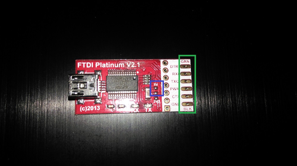
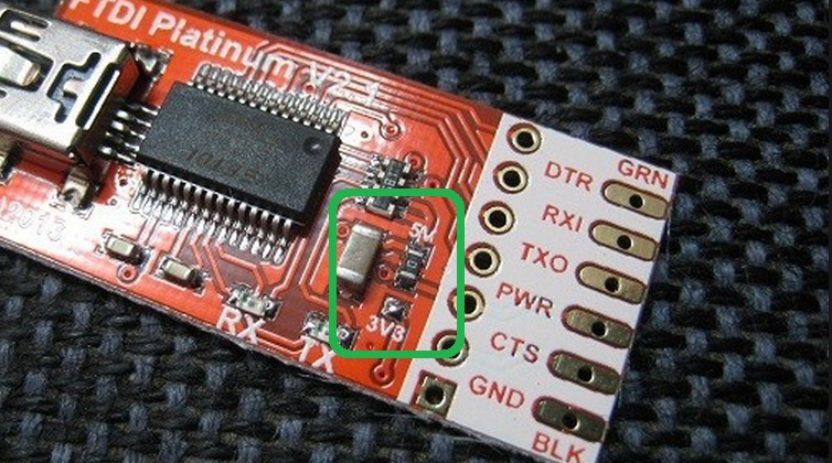
    You see in the green square marked area in the picture a 0 OHM "resistor" soldered between 2 pads. In this example 5V is chosen. If 3.3V is required you need to move this "resistor" so that it is soldered between the 3.3 marked pad and the middle pad.

    upload-0d9f8feb-13b9-4c4b-af50-317698a7fea8

    • Tomas
    1 Reply Last reply
    0
    • bpairB Offline
      bpairB Offline
      bpair
      wrote on last edited by
      #3

      Thank you very much!

      1 Reply Last reply
      0
      • S Offline
        S Offline
        shabba
        wrote on last edited by
        #4

        Hmm... I have been programming my minis (both 5v and 3,3v) without ever touching this! Am I liable to do damage or was the @bpair looking at something more permanent ?

        bpairB 1 Reply Last reply
        0
        • korttomaK Offline
          korttomaK Offline
          korttoma
          Hero Member
          wrote on last edited by
          #5

          I was using 2 FTDI boards in the beginning, one for 5V pro minis and one for 3.3V pro minis. Then I tried to use the FTDI board that was set to 3.3V on a 5V Pro Mini and it worked so now I only use the one set to 3.3V.

          If you use the 5V setting on a 3.3V arduino there is a risk that you will damage the board.

          • Tomas
          1 Reply Last reply
          0
          • S shabba

            Hmm... I have been programming my minis (both 5v and 3,3v) without ever touching this! Am I liable to do damage or was the @bpair looking at something more permanent ?

            bpairB Offline
            bpairB Offline
            bpair
            wrote on last edited by
            #6

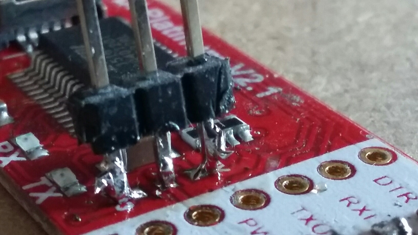
            @shabba I am very new to all of this. I was not trying to doing anything "permanent" but just protect my 3.3v Pro-Mini. But after trying to move that resistor I don't think I will move it again. It will be staying on the 3.3v pad.

            Maybe a heat gun would have been easier? I don't know like I say I am new to this.

            1 Reply Last reply
            0
            • J Offline
              J Offline
              Jan Gatzke
              wrote on last edited by
              #7

              The 3.3V pro mini and the 5V one are almost identical. The only differences are the voltage regulator (which is not used when feeding the voltage via the FTDI board) and the oscillator (8 Mhz vs. 16 Mhz). You cannot damage a pro mini 3.3V by feeding it with 5v. It will run just fine because the used MCU, atmega328p is the same in both cases. Still a pro mini 5V could run unstable at 3.3V because it has a 16 Mhz oscillator and the MCU is rated 0 - 4MHz@1.8 - 5.5V, 0 - 10MHz@2.7 - 5.5.V, 0 - 20MHz @ 4.5 - 5.5V. So it should run, but I don't have much experience with it. (But there are Arduino clones with 3.3V and 16 Mhz available) Because the NRF24 is not 5V tolerant I have set my FTDI board to 3.3V. All my sensors can deal with 3.3V, too.

              1 Reply Last reply
              0
              • TD22057T Offline
                TD22057T Offline
                TD22057
                Hardware Contributor
                wrote on last edited by
                #8

                One more note about this: If you use a 5V FTDI on a 3.3V Mini, it will work fine and program fine but VCC with be 5V. So if you're going to have a radio (3.3V) in the circuit, you have to reduce the voltage going to the radio. Normally that VCC pin is regulated down to 3.3V by the mini but not with the FTDI board. At least that's what I'm seeing on my aliexpress board. Also note - there are FTDI boards available for about the same price that have a jumper on those pads so you can easily switch between them. I ordered one of those today rather than trying to unsolder that crazy small component.

                1 Reply Last reply
                0
                • O Offline
                  O Offline
                  Omemanti
                  wrote on last edited by
                  #9

                  How about this one? Just got it in from aliexpres.

                  Shall I just connect the connectors to the green squared spots?

                  And should I connect the blue square also?
                  IMAG0248.jpg

                  korttomaK 1 Reply Last reply
                  0
                  • O Omemanti

                    How about this one? Just got it in from aliexpres.

                    Shall I just connect the connectors to the green squared spots?

                    And should I connect the blue square also?
                    IMAG0248.jpg

                    korttomaK Offline
                    korttomaK Offline
                    korttoma
                    Hero Member
                    wrote on last edited by
                    #10

                    @Omemanti best is to connect the USB cable to something and then use a multi-meter to measure GND -> PWR voltage.

                    • Tomas
                    1 Reply Last reply
                    0
                    • O Offline
                      O Offline
                      Omemanti
                      wrote on last edited by
                      #11

                      srry for the late response, the multimeter shows around the 2 volt.

                      1 Reply Last reply
                      0
                      • K Offline
                        K Offline
                        kalle
                        wrote on last edited by kalle
                        #12

                        you can close/connect the 3.3V pad with the middle pad to get 3.3V or the 5V pad with the middle pad to get 5V.
                        I suggest to bought a FTDI with a jumper.

                        FTDIwithJumper.JPG

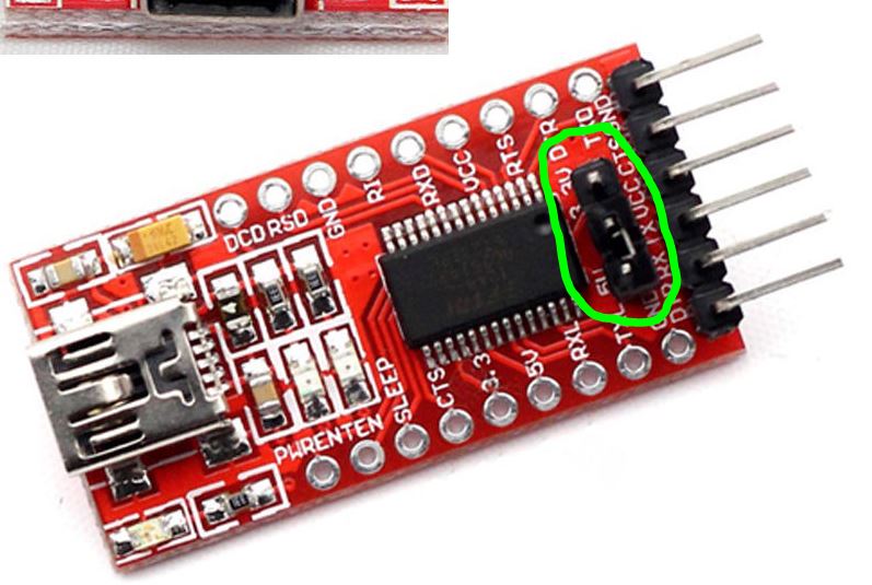
                        Your question is also answered in the second post above, because it showing exact the platinum V2.1 FTDI

                        1 Reply Last reply
                        0
                        • O Offline
                          O Offline
                          Omemanti
                          wrote on last edited by
                          #13

                          This should do the trick. 20150829_192142_resized.jpg

                          1 Reply Last reply
                          0
                          • K Offline
                            K Offline
                            kalle
                            wrote on last edited by
                            #14

                            haha, yes indeed :smile:

                            1 Reply Last reply
                            0
                            • NeverDieN Offline
                              NeverDieN Offline
                              NeverDie
                              Hero Member
                              wrote on last edited by
                              #15

                              I notice Wemos sells one which they claim can supply up to 300ma at 3.3v: https://www.aliexpress.com/store/product/WEMOS-CH340G-Breakout-5V-3-3V-USB-to-serial-module/1331105_32664922086.html?spm=2114.8147860.0.0.lHm5wW

                              So far it's the only one I've found that can supply decent current at 3.3v. A lot of the alternatives can barely supply 50ma at 3.3v. 50ma is adequate for signalling, but often not enough for also powering a project.

                              1 Reply Last reply
                              0
                              Reply
                              • Reply as topic
                              Log in to reply
                              • Oldest to Newest
                              • Newest to Oldest
                              • Most Votes


                              19

                              Online

                              11.7k

                              Users

                              11.2k

                              Topics

                              113.1k

                              Posts


                              Copyright 2025 TBD   |   Forum Guidelines   |   Privacy Policy   |   Terms of Service
                              • Login

                              • Don't have an account? Register

                              • Login or register to search.
                              • First post
                                Last post
                              0
                              • MySensors
                              • OpenHardware.io
                              • Categories
                              • Recent
                              • Tags
                              • Popular