Sensebender Micro


  • Hero Member

    @mvader yes, it is rounding the temperature difference to the nearest degree so the difference is almost always more then the 0.5.


  • Admin

    Just a hint, itead studio is starting a sale with 10% off on all imall items.. So maybe it's time to buy some Christmas presents for the inner geek 🙂


  • Oh no! Lousy timing, I just bought some...
    ... in fact, they arrived today.

    Speaking of which, whilst I got them to run the default sketch, do I actually need a programmer to do anything different, or can this be done OTA (from a Mac) ?


  • Admin

    @akbooer

    The default sketch doesn't support OTA, as it wasn't available in the stable branch at the time of launch


  • @tbowmo Good sales but did not see the Sensebender too bad .


  • Admin


  • Hero Member

    @hek I've soldered a second unit to compare, same error, I flashed back the sensebender version from the examples and on both I am stuck here: "Sensebender Micro FW 1.2radio init fail"

    Gateway is 1.5 BTW, one radio is from itead the other not.


  • Hero Member

    @Sparkman said:

    @epierre Can you confirm the settings you used in the IDE to program it?

    1.6.5 version

    Are you sure there are no solder bridges where you soldered the radio or socket for the radio?

    same behavior on two units

    Have you tried powering it with a couple of AA batteries after you uploaded the sketch?

    not yet but why should that change anything ?


  • This post is deleted!


  • Just tried out my first Sensebender...
    soldered pins and battery power...
    turn on...
    led flashes once...
    start inclusion...
    3 devices...
    Vera restarts (actually, it's openLuup running on an Arduino Yún)...
    there they are...
    and updating every minute!

    Thanks so much to all who made this level of sophistication so easy!! (Z-wave was never this simple!)

    Whilst I need a couple of temp/humidity sensors, I also need to reflash one as a 4-switch sensor. Can I do this with an Arduino Uno configured with the ArduinoISP sketch as described here ?
    https://www.arduino.cc/en/Tutorial/ArduinoISP

    Any advice or useful pointers? Thanks.


  • Admin

    @epierre

    What do you use as supply voltage for the thing? What is the output from testmode?

    Did you add a capacitor on the radio module? How did you mount them together? (picture?)


  • Admin

    @akbooer

    Should be doable with an arduino as isp. Another option is to use the serial upload.


  • I am a noob in coding so I need some advice for tuning the sensebender.ino
    current observed problems:

    1. sensor values transmitted every minutes
    2. battery level info seems wrong

    I am running the default senseblender.ino.

    on 1) What I understood in this forum, it should transmit the temp. values only every 30min (or direct when change is >.05). However, I see them arriving in my controller (Domoticz) every minute. What should I change to have it send every 30min?

    on 2) I observe in Domoticz that the battery levels reported (in the Devices section) are inaccurate. For example: one sensebender with 3.2v measured power reports 80, where I would expect round 100 (this one has new batteries). Other sensebenders with still 2.63v report 53. How to calibrate the battery measurement?

    I have been searching this forum, but was unable to find the answer.
    Alternatively, a pointer to a wiki on sensebender.ino that has this explained would work as well.


  • Admin

    @jovo

    The firmware that the sensebender is shipped with is pretty old, compared to the one that's available in the current master branch of mysensors library. A lot have been done to do better transmit control (like, limiting number of transmits etc.)

    About the battery voltage, the sensebender is measuring against an internal vref, which isn't that accurate. I can't remember the specifics at the moment, but it's hidden somewhere in the datasheet. The measurement method has a lot of inaccuracy, but on the other hand it saves external components and power.

    I didn't focus on it, but one could perhaps make some kind of calibration routine, use a known supply voltage and do some internal calculations and store an offset in eeprom.


  • @jovo for battery mesurement it's correct 100% is for 3.3V and 0% for 1.9 V (BOD fuse setting). so for 2.63 you have 52,14 %


  • Plugin Developer

    @jovo As @Fabien wrote, the default code puts 3.3 V as 100%. Look for the percentage calculation. You will see that it's basically (vcc - 1900)/14. This makes sense if using a step-up converter where you get 3.3 V. But if connecting directly to two AAs, 100% should be around 3 V. So just replace 14 with 11 in the calculation.


  • Thanks for the comments and suggestion.
    Now I have installed the master branch code from the mys. library.
    Unfortunately no change. Still very frequent updates (under the same circumstances).
    I sense it has something to do with :
    bool tx = force;
    but I am not quite sure where to change it in.
    I will continue my search.....


  • Admin

    @jovo

    There is a small error in the sketch, that falsely converts floats to ints. Look at line 243, it's dividing by 100:

    float diffTemp = abs(lastTemperature - (isMetric ? data.celsiusHundredths : data.fahrenheitHundredths)/100);
    float diffHum = abs(lastHumidity - raHum.getAverage());
    

    This should be changed to 100.0 instead. This way the calculation is returning as a float.

    float diffTemp = abs(lastTemperature - (isMetric ? data.celsiusHundredths : data.fahrenheitHundredths)/100.0);
    float diffHum = abs(lastHumidity - raHum.getAverage());


  • @fabian how is the box working out were there any mods and are the stl files ready yet?


  • ok, it seems the aggregated upload is solved with the change from Thomas.
    Now I modify the "14" in "11" as suggested by martin. I have 105% now, but that could be right because I measure 3.1V from my 2 fresh AA's

    The only 'new issue' I discovered is that one sensor actually stops being received updates from due low power. The measured voltage on the batteries is still 2.1V and the battery indicator was at 23%.
    Could it be that I have bad fake radios that don't operate lower then 2.1V? (since there is no other external components added to my setup, I suspect only the radios).


  • @5546dug said:

    @fabian how is the box working out were there any mods and are the stl files ready yet?

    Sorry, my 3D printer is out of service, I'm waiting for chinese parts ... I will post correct STL files in 1 or 2 weeks.


  • I'm having trouble with the transmission times.

    // How many milli seconds between each measurement 900000 is 15 minutes
    #define MEASURE_INTERVAL 900000
    
    // How many milli seconds should we wait for OTA? 3000 is 3 seconds
    #define OTA_WAIT_PERIOD 3000
    
    // FORCE_TRANSMIT_INTERVAL, this number of times of wakeup, the sensor is forced to report all values to the controller
    #define FORCE_TRANSMIT_INTERVAL 30 
    
    // When MEASURE_INTERVAL is 60000 and FORCE_TRANSMIT_INTERVAL is 30, we force a transmission every 30 minutes.
    // Between the forced transmissions a tranmission will only occur if the measured value differs from the previous measurement
    

    I would expect a wake up and measure every 15 minutes. transmit if greater than .5 and go back to sleep
    also i would expect a forced transmission every 30 minutes.
    but that doesn't seem to be happening.
    here are my last few transmit times
    4:07pm
    5:59pm
    6:15pm
    6:47pm
    7:50pm
    8:34pm
    9:10pm

    I don't see a static 30 minute transmit.
    (from 4pm to 6pm?) i'm sure the temp and/or hum changed in 2 hours

    any suggestions on what may be wrong?
    default sketch (1.3 from git) but changed the measure intervals
    sensor lib 1.5
    thanks


  • @mvader If your interval between readings is 15 minutes and the force transmit interval is 30, your actual interval is 15minutes * 30 = 7.5hours. Also, see this thread for sleep time accuracy. 15 minutes of sleep can last 16-17 minutes...


  • @Dwalt said:

    @mvader If your interval between readings is 15 minutes and the force transmit interval is 30, your actual interval is 15minutes * 30 = 7.5hours. Also, see this thread for sleep time accuracy. 15 minutes of sleep can last 16-17 minutes...

    really.. hmm
    so if you look at the default comment
    when MEASURE_INTERVAL is 60000 and FORCE_TRANSMIT_INTERVAL is 30, we force a transmission every 30 minutes.
    That says measure for temp/hum every 1 minute - send if greater than .5 (defined later in the sketch)
    regardless of what goes on send stats every 30 minutes

    can you help me understand why those 2 number would be multiplied together? one shouldn't have anything to do with the other.
    i read that as they are definitions for 2 different process.
    but i may be totally misunderstanding.

    I do buy the sleep accuracy part of it though 🙂


  • @mvader No, it is not 30 minutes, the FORCE_TRANSMIT_INTERVAL counts the number of 'wakeup and take a reading' events, which in the original sketch is every 60 seconds. After 30 wakeup-and-read without a transmit, force a transmit. If you change your FORCE_TRANSMIT_INTERVAL to 2, it will transmit every 30 minutes if the readings do not change more than 0.5.

    The MEASURE_INTERVAL is based upon time (millis) and the FORCE_TRANSMIT_INTERVAL is based upon counting events (wakeup cycles).


  • @Dwalt said:

    @mvader No, it is not 30 minutes, the FORCE_TRANSMIT_INTERVAL counts the number of 'wakeup and take a reading' events, which in the original sketch is every 60 seconds. After 30 wakeup-and-read without a transmit, force a transmit. If you change your FORCE_TRANSMIT_INTERVAL to 2, it will transmit every 30 minutes if the readings do not change more than 0.5.

    thanks for the clarification! 👍


  • @hek said:

    @gbfromhb

    D3 is available on the side-pins. D2 is routed to the radio but can be used with some hacking.

    I need 2 interrupts and would prefer using the external interrupts even though it might work with pin change interrupts. When looking through the forum I saw this answer from @hek but have not found any further reference to how this should be done in order not to disturb any radio functions. Anyone knows?


  • Admin

    I don't know if the radio actually drives the interrupt "output" pin on it's pinheader as default, or if you have to set it up when initializing the radio (@hek might have some input on this part :))

    If it drives the interrupt pin by default, then you need to either cut a trace on the sensebender, or cut / remove the pin in the pinheader on the radio module.


  • Admin

    @tbowmo said:

    I don't know if the radio actually drives the interrupt "output" pin on it's pinheader as default,

    I think it does actually.


  • @hek Is it needed for the radio to work or can I just cut it (seems odd to attach the radio to D2 if it is not really needed for anything).


  • Admin

    No, it isn't currently used by the MySensors library. It could be used to wake up the board when detecting radio transmissions...
    But keeping MCU sleeping and the radio listening still uses up batteries far too quickly so I guess it's still not an option.


  • @hek @tbowmo Thanks! Cut the radio IRQ pin and soldered a connection to D2. Tested to attach both interrupts and it works using a modified SenseBenderMicro sketch. "The Thing" will when ready be placed in my mailbox (which has mail-in and mail-out doors) and as a bonus report the outside temp, humidity and battery status. Does not solve any of this worlds biggest problems but it is fun 🙂


  • Hello,

    one simple quick question, does this board can be used to create door sensors ? I do not need the temp/hum sensors, but I'm interested with the small footprint and the battery optimized board to make smallest door sensors (and some buttons).

    regards,


  • Admin

    @petoulachi

    Yes, it could be made into a door / window sensor.. (I'm planning on doing that myself).

    However, you need to build your own, if you don't want the temperature/humidity sensor on it.


  • @tbowmo
    Well can't I use this board without using the temp/hum sensor ?

    This board is quite small and allows to stack the radio module with minimum place. Also it works at 1Mhz, I guess it's a bit better than an Arduino Pro @ 3.3V ?


  • Admin

    Yes, you can use it without using the temp/hum sensor....

    I just assumed, that as you wouldn't make use of it, you would like to have it removed from the board as well..


  • Well I do, but I think that using a Arduino Pro 3.3V will be less effecient, but maybe I'm wrong ?

    I'm currently using temp/hum/motion sensors with Arduino Pro 5V, but they are not battery powered. Now I need to make very small sensor with battery, and I thought that maybe this sensebender board is my solution ?


  • Contest Winner

    @petoulachi to make the pro mini as efficient as the SenseBender, you need to cut some traces on the board. There are forum topics for battery optimizing a pro mini. The SenseBender has these optimizations built in.


  • That's why I think i'm going to go with this senseboard.
    But I want to be sure that some connectors (D3 ?) support interrupts ? The goal is to have the sensor always in sleep mode, and wake up on interrupts only.

    Regards,


  • @petoulachi D3 can be used for interrupt, just tested it and it works.


  • I vote for one cheap Sensebender version without the temp/hum sensor on it. It will be the perfect door/window sensor.


  • Admin

    @nikos1671

    It has been up before, but back then it was decided that we don't save that much (2-3 $ or something like that). It might also be lower production quantities, which also keeps the price up..


  • @tbowmo just curious do you guys know how many of these you've sold?
    I've bought about 15+ 🙂


  • Admin

    @mvader
    Then you've bought almost 2% of them 🙂

    We're deeply grateful for yours and others support of the MySensors project.


  • Ordered 6 board too ! I'm glad to support MySensors project !


  • I've got 3 coming, can't wait to figure out what I'm going to use them for 🙂


  • @timropp said:

    I've got 3 coming, can't wait to figure out what I'm going to use them for 🙂

    I'm deploying mine all over the house.
    in my attics, garage, shed. bedrooms. etc
    I've attached motion and lux sensors to several of them already.
    I tested / proof of concept adding IR transmitters. but these will likely need to be 5v nano's or something as battery power probably won't work with the IR and staying away waiting for messages from the controller.


  • Got 3 up just using the built in temp/humidity, making sure all looks ok. Will slowly add motion.

    Any suggested motion sensor for these guys?


  • @NotYetRated said:

    Got 3 up just using the built in temp/humidity, making sure all looks ok. Will slowly add motion.

    Any suggested motion sensor for these guys?

    I'm using that HC501 PIR
    you can connect to the side pin and use 3v instead of the 5v


  • Hardware Contributor

    @mvader Can you elaborate how you use 3V on the HC501 ? Which side pin ? Can you post an image ?


  • @GertSanders
    if you look at this image
    on the left side where it says "H" by the 3 pins with the jumper.
    i take off the jumper and connect 3v to the H pin
    works great.
    http://www.bdspeedytek.com/wp-content/uploads/1.1.jpg


  • Hardware Contributor

    @mvader Thanks !


  • Admin

    My Sensebender node started June 10 is still going strong.

    Screen Shot 2015-11-12 at 20.04.18.png


  • Contest Winner

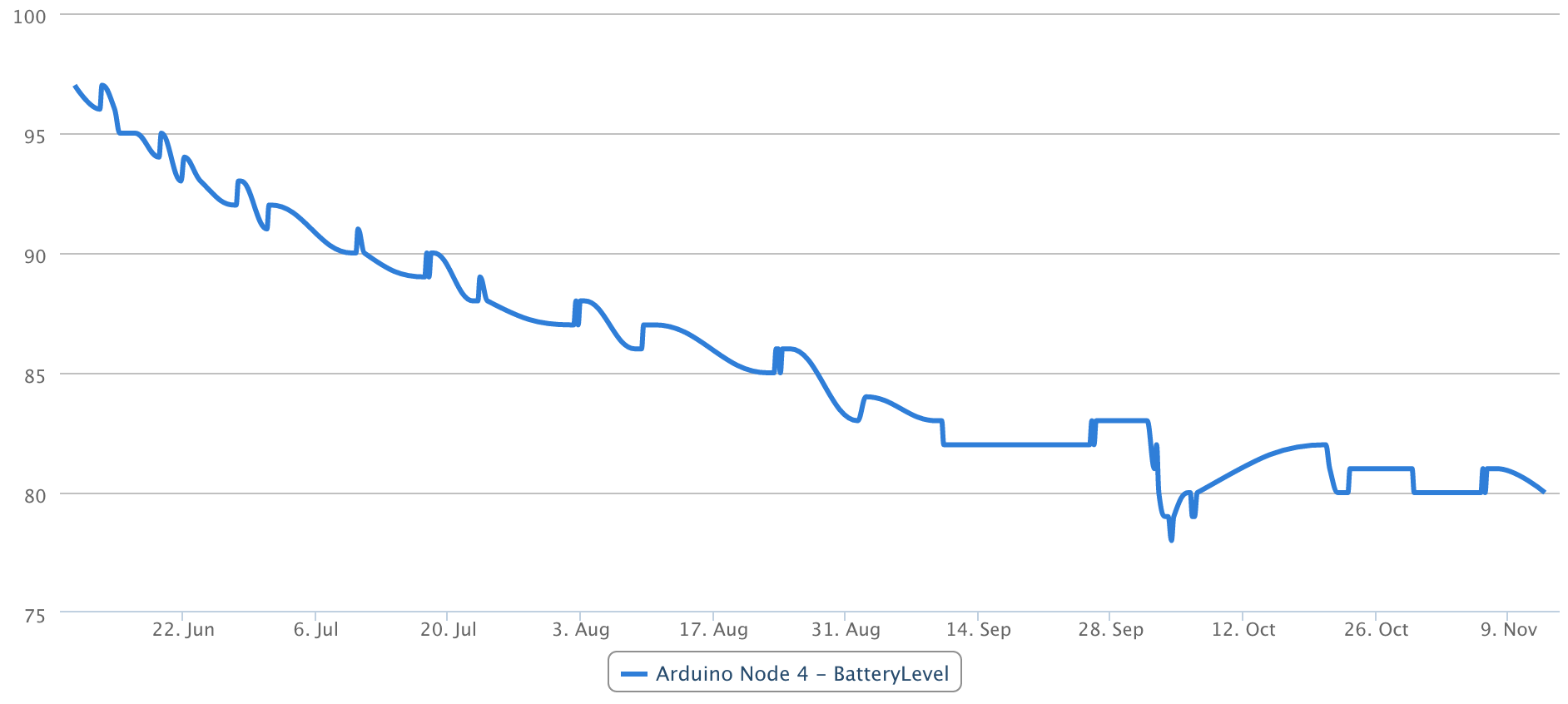
    @hek nice, what tool do you use for logging/graphing? Or is it exported and post-processed?


  • Admin

    @Anticimex

    Datamine for Vera. The actual data is stored to my NAS (mounted from vera).


  • Contest Winner

    @hek cool. Can Vera do that now? Vera lite as well? Though the data miner plugin only could use USB mounts.


  • Admin

    @Anticimex said:

    Can Vera do that now? Vera lite as well? Though the data miner plugin only could use USB mounts.

    Na, a little hack
    http://forum.micasaverde.com/index.php/topic,14910.0.html


  • Hello,
    I've just received my sensebender boards and start playing with it.

    My first goal is to make a door sensor running on battery. I will not use the integrated temp/hum sensor for battery purpose, and use interrupt to have the sensor on sleep the majority of time.

    Looking at the sketch given with temp/hum, I have one question;

    on the loop function, we have

    if ((measureCount == 5) && highfreq) 
      {
        clock_prescale_set(clock_div_8); // Switch to 1Mhz for the reminder of the sketch, save power.
        highfreq = false;
      } 
    

    But I don't really understand this ; highfreq is initialized to true in the declaration, and never again. So, does this clock_prescale_set is call only once, meangin that the sensor will run at 1Mhz all the time ?
    It is the 5 first mesure that are running at normal speed, and then the sensor goes into a "battery efficient" mode ?
    Why waiting for 5 mesure to do so, and not doing it at startup ?

    Thanks for your explanation !


  • Admin

    @petoulachi said:

    But I don't really understand this ; highfreq is initialized to true in the declaration, and never again. So, does this clock_prescale_set is call only once, meangin that the sensor will run at 1Mhz all the time ?
    It is the 5 first mesure that are running at normal speed, and then the sensor goes into a "battery efficient" mode ?
    Why waiting for 5 mesure to do so, and not doing it at startup ?

    Thanks for your explanation !

    It's waiting with switching to lower frequency, because it is dumping debug information to the serial port. And when you switch to 1Mhz, the baudrate is "screwed".

    When that's said, my opinion is that there is not much power to save, with switching to 1Mhz. This is because the MCU is sleeping most of the time, with the RC oscillator switched off. I am thinking that the freq. scaling should be removed in the comming releases


  • Oooh so I guess that also explain why I have strange output on the serial using the default sketch ?

    Well, I'll start without touching frequency and see how it behave in the next month. This is the sketch I use (not tested yet !). Sleeping all the time, awake but interrupt. When awake, send the Battery % if different from last mesure.

    /**
     * The MySensors Arduino library handles the wireless radio link and protocol
     * between your home built sensors/actuators and HA controller of choice.
     * The sensors forms a self healing radio network with optional repeaters. Each
     * repeater and gateway builds a routing tables in EEPROM which keeps track of the
     * network topology allowing messages to be routed to nodes.
     *
     * Created by Henrik Ekblad <henrik.ekblad@mysensors.org>
     * Copyright (C) 2013-2015 Sensnology AB
     * Full contributor list: https://github.com/mysensors/Arduino/graphs/contributors
     *
     * Documentation: http://www.mysensors.org
     * Support Forum: http://forum.mysensors.org
     *
     * This program is free software; you can redistribute it and/or
     * modify it under the terms of the GNU General Public License
     * version 2 as published by the Free Software Foundation.
     *
     *******************************
     *
     * REVISION HISTORY
     * Version 1.0 - Henrik Ekblad
     * 
     * DESCRIPTION
     * Default sensor sketch for Sensebender Micro module
     * Act as a temperature / humidity sensor by default.
     *
     * If A0 is held low while powering on, it will enter testmode, which verifies all on-board peripherals
     *  
     * Battery voltage is as battery percentage (Internal message), and optionally as a sensor value (See defines below)
     *
     */
    
    
    #include <MySensor.h>
    #include <Wire.h>
    #include <SPI.h>
    #include "utility/SPIFlash.h"
    #include <EEPROM.h>  
    #include <avr/power.h>
    
    
    #define RELEASE "1.0"
    
    // Child sensor ID's
    
    #define DIGITAL_INPUT_SENSOR 3   // The digital input you attached your motion sensor.  (Only 2 and 3 generates interrupt!)
    #define INTERRUPT DIGITAL_INPUT_SENSOR-2 // Usually the interrupt = pin -2 (on uno/nano anyway)
    #define CHILD_ID_DOOR 1   // Id of the sensor child
    
    
    MySensor gw;
    
    // Sensor messages
    MyMessage msgDoor(CHILD_ID_DOOR, V_TRIPPED);
    
    // Global settings
    int measureCount = 0;
    int sendBattery = 0;
    boolean highfreq = true;
    
    // Storage of old measurements
    long lastBattery = -100;
    boolean oldDoorValue;
    
    /****************************************************
     *
     * Setup code 
     *
     ****************************************************/
    void setup() {
      Serial.begin(115200);
      Serial.print(F("Sensebender Micro FW "));
      Serial.print(RELEASE);
      Serial.flush();
      
      gw.begin();
    
      Serial.flush();
      Serial.println(F(" - Online!"));
      gw.sendSketchInfo("Battery Door", RELEASE);
    
      // sets the motion sensor digital pin as input
      pinMode(DIGITAL_INPUT_SENSOR, INPUT);     
      // Activate internal pull-ups
      digitalWrite(DIGITAL_INPUT_SENSOR, HIGH);
      
       // Register all sensors to gw (they will be created as child devices)
      gw.present(CHILD_ID_DOOR, S_DOOR);
    }
    
    
    /***********************************************
     *
     *  Main loop function
     *
     ***********************************************/
    void loop() {
      gw.process();
    
      sendBattLevel(false); 
      door(false);
      
      gw.sleep(INTERRUPT, CHANGE, 0);
    }
    
    //  Check if digital input has changed and send in new value
    void door(bool force) 
    {
      // Short delay to allow buttons to properly settle
      sensor_node.sleep(5);
      
      bool tx = force;
      
      boolean tripped = digitalRead(DIGITAL_INPUT_SENSOR) == HIGH; 
      
      if (tripped != oldDoorValue) 
      {
        tx = true;
        oldDoorValue = tripped;
      }
      if (tx)
      {
         // Send in the new value
         gw.send(msgDoor.set(tripped ?  1 : 0));  // Send tripped value to gw 
      }
    } 


    /********************************************
     *
     * Sends battery information (battery percentage)
     *
     * Parameters
     * - force : Forces transmission of a value
     *
     *******************************************/
    void sendBattLevel(bool force)
    {
      if (force) lastBattery = -1;
      
      long vcc = readVcc();
      
      if (vcc != lastBattery) 
      {
        lastBattery = vcc;
    
        // Calculate percentage
        vcc = vcc - 1900; // subtract 1.9V from vcc, as this is the lowest voltage we will operate at
        long percent = vcc / 14.0;
        gw.sendBatteryLevel(percent);
      }
    }
    
    /*******************************************
     *
     * Internal battery ADC measuring 
     *
     *******************************************/
    long readVcc() {
      // Read 1.1V reference against AVcc
      // set the reference to Vcc and the measurement to the internal 1.1V reference
      #if defined(__AVR_ATmega32U4__) || defined(__AVR_ATmega1280__) || defined(__AVR_ATmega2560__)
        ADMUX = _BV(REFS0) | _BV(MUX4) | _BV(MUX3) | _BV(MUX2) | _BV(MUX1);
      #elif defined (__AVR_ATtiny24__) || defined(__AVR_ATtiny44__) || defined(__AVR_ATtiny84__)
        ADMUX = _BV(MUX5) | _BV(MUX0);
      #elif defined (__AVR_ATtiny25__) || defined(__AVR_ATtiny45__) || defined(__AVR_ATtiny85__)
        ADcdMUX = _BV(MUX3) | _BV(MUX2);
      #else
        ADMUX = _BV(REFS0) | _BV(MUX3) | _BV(MUX2) | _BV(MUX1);
      #endif  
     
      delay(2); // Wait for Vref to settle
      ADCSRA |= _BV(ADSC); // Start conversion
      while (bit_is_set(ADCSRA,ADSC)); // measuring
     
      uint8_t low  = ADCL; // must read ADCL first - it then locks ADCH  
      uint8_t high = ADCH; // unlocks both
     
      long result = (high<<8) | low;
     
      result = 1125300L / result; // Calculate Vcc (in mV); 1125300 = 1.1*1023*1000
      return result; // Vcc in millivolts
    }


    BTW, what is the F() function ? instead of Serial.print("Sensebender Micro FW "); why using Serial.print(F("Sensebender Micro FW ")); ?

    Thanks !


  • Started to solder my 6 sensebender. I've noticed that if I set it to 1Mhz directly, the sensor cannot register itself on the gateway (but unfortunately I dont know why because there's no serial). Putting it at 8Mhz, being detected by the GW with an ID, and I can set it back to 1mhz. Weird.


  • Oh and BTW, which boxes are you using with your Sensebender ? I guess it's maybe the most difficult part of the entire project, finding the perfect box 😄


  • No, finding a box is the easiest part. This is the "box" for my outdoor temperature. 😆
    sensebender.jpg


  • Admin

    Wonder how well the hum-sensors work in that enclosure 🙂


  • Hmm, would Gore-Tex work? I will try find a Gore-Tex bag for the next version 🙂


  • @Fabien said:

    @5546dug said:

    @fabian how is the box working out were there any mods and are the stl files ready yet?

    Sorry, my 3D printer is out of service, I'm waiting for chinese parts ... I will post correct STL files in 1 or 2 weeks.

    @Fabien @5546dug
    Hi, any news on this please? I would be good to get a box by Christmas.


  • Admin

    @petoulachi

    The sketch have improved a lot since we released the sensebender, mostly on determining when to power up the radio and transmit. This should save more power. I've got one running with latest development, without hiccups for the last couple of months (it also have Ota fw upgrade enabled by default now).

    So if you are "adventurous" I would recommend to put that into your sensebenders


  • I am adventurous !

    Were can I find the beta version of the sketch ?


  • Hero Member


  • Thanks !

    I took a look at the sketch, I didn't know there was a presentation() method to implement to present the different sensor's ID; is this new ? when is it called? I guess after setup() ?


  • Admin

    @petoulachi

    That's a part of the development. Things are re-arranged in the sketches, to make things more configurable (from within the sketch itself).

    It will be part of the next release (I don't know when that is happening)


  • Ok, related to MySensors 1.6 tehen, that explain why I never seen this !


  • HI, I'm about to experiment with a modded version of the sensebender and I while looking at the schematics of the original sensebender, I see that the crystal does not have any pf capasitors and not connected to GND. Why is that?

    All other schematics of atmega or any microprocessor I've seen has dual 22pf caps over the crystal and connected to ground.


  • Admin

    @Magnus-Pernemark

    The sensebender was designed to use a 32Khz oscillator for lowpower operation. According to the datasheet (page 33) it is not necessary to have external load capacitors if the crystals datasheet specifies cL below 6pF.

    However, we decided early on that an external crystal is not necessary in our application. So that is why it is not mounted, but the pads are still there, in case someone would use it.


  • @tbowmo Thanks! Yes. I read that it was not needed, but since it said "if you want higher precision" I though that, higher is good, and it would not hurt to place one there. But the crystals I have are 12.5pf so I guess I can't use them, but on the other hand I don't need to buy any other


  • Did someone "test" the humidity precision of the Si7021on the sensbender? Of corse the datasheet says max 3% off but how reliable is that?

    I have other sensors here and they differ by about 10%. So I did a "Salt-Calibration-Test" and there my two sensbenders or better Si7021 are 6% over the reference value. They report 81% and it should be 75%.

    Note: It's my first time that I performed this test and I'm not 100% sure that the (water-salt-ratio) is correct - thats why I'm interested if someone else tested the values?


  • Admin

    @nivoc

    Salt and electronics isn't a good combination, it will cause corrosion of the copper tracks..

    Just to warn you a little bit 🙂


  • @tbowmo Thanks. No worries the electronic won't touch the salt or water. The salt/water is just within the same closed container to bring the enclosed air to exactly 75.3% rel hum (at 25C).

    I followed this howto: But there are many other similar ones.
    http://www.kingofthehouse.com/hygrometer/


  • @nivoc I setup several sensebenders on battery last summer and noticed they were a few % below two dht22 I had been running for months. I did the saturated salt test on three sensebenders with one dht22 and one mechanical hygrometer and the sensebenders all read 74-75% while the DHT and hygrometer read 78-80%. Not a perfect test and i dont know which devices were correct but one thing I noticed was the sensebenders consistently provided the same result across different devices. Relative humidity is relative.


  • @Dwalt
    Thanks for the info. I'm currently opening the box every several hours to test the salt soup. My room has something between 50 and 60 rel. (so below 75). And every time I open the box this (see pic). It drops and goes back up to 82 or 83. Than it stabilizes there over the next couple hours. There are two sensbenders in the box - thats what the two line are. And yes they are remarkable equal. But it always goes to 82 - i would hope for 75. But I will repeat this procedure until it starts to stabilizes after every opening a little bit below the value that was there before the opening. Because if that happens i am below the dry point and than I will test in a room with humidity higher than 80 and test if soup can do the same into the other direction and holds it stable for many openings. THAN i know that the salt is performing is job correctly and know that the test is good and the senbender is wrong 🙂 or hopefully I learn the opposite.

    upload-555b12a4-6bc0-4e07-acf7-976c4122e6d6


  • Yes it looks like that the sensors are 8% off. I tested the other way around >opening at ~100rel and closing and same + exactly back to 82/83 and it should be 75% :-).

    upload-e6c04b83-54d0-4e1e-aef3-a36b72c760d5


  • In the new year I will test with "Magnesium chloride". It brings the rel humitity to exactly 32% - I will report how that goes 🙂


  • Admin

    If the Si7021 is exposed to high humidity for a prolonged period, the RH% measurement will shift upwards, according to the datasheet, page 15, section 4.3

    Extract from Datasheet:

    4.3. Prolonged Exposure to High Humidity
    Prolonged exposure to high humidity will result in a gradual upward drift of the RH reading. The shift in sensor
    reading resulting from this drift will generally disappear slowly under normal ambient conditions. The amount of
    shift is proportional to the magnitude of relative humidity and the length of exposure. In the case of lengthy
    exposure to high humidity, some of the resulting shift may persist indefinitely under typical conditions. It is generally
    possible to substantially reverse this affect by baking the device (see Section “4.6. Bake/Hydrate Procedure” ).


  • Hero Member

    @petoulachi said:

    BTW, what is the F() function ? instead of Serial.print("Sensebender Micro FW "); why using Serial.print(F("Sensebender Micro FW ")); ?

    It's a way to save some RAM. A simple string constant like "Hello" takes up 6 bytes of RAM and also 6 bytes of Flash (program) memory (6 bytes includes a single "hidden" byte of binary zero as an end-of-text marker). At startup and before your code executes, that bit of program memory is copied to RAM. The F() thing is a "macro" which causes the compiler save only the 6 bytes of Flash (no Ram used). The print function can (through C++ typing) fetch those 6 bytes from Flash at runtime for printing. If you have long or many text constants in your program, this can add up to some useful savings,when you only have 2K of RAM.

    See the "F() Macro" on this page: https://www.arduino.cc/en/Reference/PROGMEM


  • @tbowmo Good hint. But it is happening to all three sensbeners for at least one month now. (different orders). I now got 4 more so I will test again soon.

    Over xmas I tested also with magnesium chloride hexahydrate. magnesium chloride hexahydrate produces exactly 33%rel.

    All 3 sensbenders report exactly 39% or 40%. So they are also here 7% off. But almost the same value and very reproducible - so thats great!

    upload-6b1782fc-cf3e-45b8-ad15-890b7eef84a0


  • @tbowmo I'm now almost sure that my test-setup has no faults very reproducable and read many articles - I plan to verify my findings with someone who has a professional calibrated device.

    I saw in a museum nearby that they have professional calibrated devices 🙂
    upload-4464b273-5525-48b2-a940-10826e61f030

    So I will test against those 🙂


  • Admin

    @nivoc

    Have you tried to "bake" your sensebenders, in case they have been exposed to high humidity for a longer time?

    They are, as far as I know, produced in a part of China, which are known to have very high humidity. (been traveling there a lot some years ago)


  • Hero Member

    @nivoc
    I can confirm your results: I am running two different sensors in the same room next to each other. The sensebender is always above the dht-22. Right now it is
    52% to 47.8% rel. humidity, while the temperature is 17.8 to 17.9 (which is nearly equal).


  • @tbowmo No I haven't baked yet. I will try that but not in the next two weeks. But I will report back.


  • But I tested tonight with distilled water - so should be exactly 100%. And again (I didn't know that thats possible) I got 104 and 107% so slightly above (still increasing). Thats great b/c that means all values are about 7-8% too high.
    At 33% the reading was about 40%
    At 75% the reading was about 83%
    At 100% the reading was about 106%

    So reading minus 8% gives a pretty accurate result. In the next few days i will test 3 more sensbender.

    Distilled Water (100% expected):
    upload-c0364fcd-876d-4701-a3ec-b0c55efc04a6


  • Read the spec for the humidity sensor used in the sensebender (Si7021 integrated humidity / temperature sensor.)
    Precision Relative Humidity Sensor: ± 3% RH (max), 0–80% RH
    To my reading this is actually 6% wrong reading to one of the sides - so when you are measuring yours to be 8% off, is caused that you are using the device outside of humidity range 100% and max is 80%

    Link to spec:
    https://www.silabs.com/Support Documents/TechnicalDocs/Si7021-A20.pdf

    What I want you to know, if your device is reading within 6 % of the value - it's still reading correct. and when you compare ex DHT22 that device also have some reading variation error. Do not expect to get 100% perfect value for 2 devices...


  • @bjacobse Yes and no 🙂

    Yes 100% is outside of the spec.

    And no. 33% with Magnesium Chloride Hexahydrate is inside the spec and I get 40% instead of 33-34%.

    Max off should be 3% above or? Means 37% - but fair enough. Should be ok for household use.


  • @nivoc said:

    @bjacobse Yes and no 🙂

    Yes 100% is outside of the spec.

    And no. 33% with Magnesium Chloride Hexahydrate is inside the spec and I get 40% instead of 33-34%.

    Max off should be 3% above or? Means 37% - but fair enough. Should be ok for household use.

    I hope the Temp measurements are not off by that much.
    i don't need .00001 accuracy or anything. but i feel a big difference between 70 and 72 in my house.


  • @mvader
    Spec is: High Accuracy Temperature Sensor ±0.4 °C (max), –10 to 85 °C
    So the temp accuracy is quite good


  • @nivoc
    Yes you are right, +-3 from your humidity solution on 33%, then the reading could be in the interval 33-3=30% or up to 33+3=36% and should not show 40%

    did you get same false readings from other sensebender humidity sensors?


  • @bjacobse Yes I have 3 sensbener running from 2 different orders. All 3 are very near by each other. So at 33% they all read something near to 40%.

    I have 4 more sensbenders to build. However I continue to test tonight with a Boveda-Pack that claims to bring the hum in a containter to exactly 69%. I did 4 test's so far and also used different technics. So i get more and more confident.

    But the very good thing is - it looks every reproducible. So the value may be off but reproducable accurate off by about 8%. When I completed my test it will be very easy to correct it within the software.


  • @mvader I haven't made any very accurate temp testings. But the readings are exactly the same than other non-sensbender devices in my home. I started researching the humidity b/c I had different readings between different devices.

    Temp looks fine to me.


  • What is the current consumption of the Sensebender during sleep and active modes?

    Thanks,
    Tony


  • Admin

    @tcontrada

    there are some measurements in the old design thread here http://forum.mysensors.org/topic/510/minimal-design-thoughts


  • Hi. What case you all using for the sensebender ?Any good idea.


Log in to reply
 

Suggested Topics

  • 3
  • 109
  • 110
  • 5
  • 2
  • 2

1
Online

11.2k
Users

11.1k
Topics

112.5k
Posts