Gateway unable to assign ID to Temperature Sensor example
-
Hi,
I'm trying to connect a temperature sensor to a server. However the automatic assignment of the ID seems to be failing.
The temperature sensor is build according to the default sample: http://www.mysensors.org/build/temp. (controller = Mini Arduino Pro 8MHz, 3V3)
The gateway is a serial gateway with the LEDs as added bonus according to: http://www.mysensors.org/build/serial_gateway and http://www.mysensors.org/build/advanced_gateway. (controller - Arduino Uno, 16MHz, 5V)
To wrap-up the hardware site I didn't install the capacitors for the NRF24L01+ transceiver but the communication itself seems to be OK.
As a server I'm using a Raspberry Pi B2.On the software site I have the following:
The Temperature sensor is running the sample found on http://www.mysensors.org/build/temp.
The gateway is running the sample found on http://www.mysensors.org/build/serial_gateway.
And on my PI I'm using the NodeJsController from https://github.com/mysensors/Arduino/tree/master/NodeJsController with Node 12.0 and MongoDB (as per sample).Now I do the following: The gateway is connected. Start the NodeJsController (with "node NodeJsController.js"), (re)start the Temperature sensor.
The output from the console is below:Connected to database at mongodb://127.0.0.1:27017/MySensorsDb connected to serial gateway at /dev/ttyACM0 connected to serial gateway at /dev/ttyACM0 <- 0;0;3;0;14;Gateway startup complete. <- 0;0;3;0;9;read: 255-255-0 s=255,c=3,t=3,pt=0,l=0: <- 255;255;3;0;3; -> 255;255;3;0;4;1 <- 0;0;3;0;9;read: 255-255-0 s=255,c=3,t=3,pt=0,l=0: <- 255;255;3;0;3; -> 255;255;3;0;4;1 <- 0;0;3;0;9;read: 255-255-0 s=255,c=3,t=3,pt=0,l=0: <- 255;255;3;0;3; -> 255;255;3;0;4;1 <- 0;0;3;0;9;read: 255-255-0 s=255,c=3,t=3,pt=0,l=0: <- 255;255;3;0;3; -> 255;255;3;0;4;1 <- 0;0;3;0;9;read: 255-255-0 s=255,c=3,t=3,pt=0,l=0: <- 255;255;3;0;3; -> 255;255;3;0;4;1 <- 0;0;3;0;9;read: 255-255-0 s=255,c=3,t=3,pt=0,l=0: <- 255;255;3;0;3; -> 255;255;3;0;4;1 <- 0;0;3;0;9;read: 255-255-0 s=255,c=3,t=3,pt=0,l=0: <- 255;255;3;0;3; -> 255;255;3;0;4;1 <- 0;0;3;0;9;read: 255-255-255 s=255,c=3,t=7,pt=0,l=0: <- 0;0;3;0;9;send: 0-0-255-255 s=255,c=3,t=8,pt=1,l=1,st=fail:0If I now edit line 26 in the temperature controller sample to:
gw.begin(NULL, 1, false);The output is the following:
Connected to database at mongodb://127.0.0.1:27017/MySensorsDb
connected to serial gateway at /dev/ttyACM0
connected to serial gateway at /dev/ttyACM0
<- 0;0;3;0;14;Gateway startup complete.
<- 0;0;3;0;9;read: 1-1-0 s=255,c=0,t=17,pt=0,l=3:1.4
<- 1;255;0;0;17;1.4
<- 0;0;3;0;9;read: 1-1-0 s=255,c=3,t=6,pt=1,l=1:0
<- 1;255;3;0;6;0
-> 1;255;3;0;6;M

<- 0;0;3;0;9;read: 1-1-0 s=255,c=3,t=11,pt=0,l=18:Temperature Sensor
<- 1;255;3;0;11;Temperature Sensor
<- 0;0;3;0;9;read: 1-1-0 s=255,c=3,t=12,pt=0,l=3:1.0
<- 1;255;3;0;12;1.0
<- 0;0;3;0;9;read: 1-1-0 s=0,c=0,t=6,pt=0,l=3:1.4
<- 1;0;0;0;6;1.4
<- 0;0;3;0;9;read: 1-1-0 s=0,c=1,t=0,pt=7,l=5:20.7
<- 1;0;1;0;0;20.7
Working!!!
So there seems to be a problem with the automatic assignment of the IDs.
I already tryed the to erase the eeprom on the temperature controller but this din't work as well (sketch: https://codebender.cc/sketch:108438)Hope you can help.
-
Update:
I just edited the temperature sample to include the #define DEBUG statement at the beginning of the temperature transmitter sample, also I added a 10uF capacitor on the supply lines of the NRF24L01+ transceiver on the side of the temperature transmitter.
The debug output is below:
sensor started, id 255
req node id
send: 255-255-0-0 s=255,c=3,t=3,pt=0,l=0,st=ok:
<repeated x times>
<I also have lines containing:>
send: 255-255-0-0 s=255,c=3,t=3,pt=0,l=0,st=fail:
Hope this helps
Edit:
I'm wondering: is there a way to do some "ping-pong" between the gateway and my sensor so I can test the range and/or look for problems in the communication (and maybe even start complaining about the NRF24L01+ transceiver with my supplier is that is the case..) -
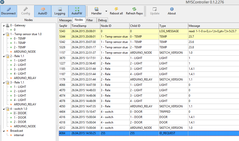
I reccomend you to install myscontroller.
http://www.mysensors.org/controller/myscontroller
You are able to send test messages with acknowledgement.
The program is excellent for checking all the sensors!
-
Ok, So I got myscontroller running on windows. (Looks good) So now for the rest.
If I use automatic ID assignment I'm still not getting the ID assigned although myscontroller is trying to set the ID.
So since I expected that the NRF24L01+ transceiver could be wrong I just tried swapping the transceivers from the gateway and the sensor. However the ID still can't be assigned by myscontroller.
Any other suggestions on what I can check if the comms is working.
I now also tried the following sketch with the sensor in repeater mode so I'm "forcing" the comms to be alive (at least, I hope) but this also won't work.
https://codebender.cc/sketch:108647So now I have 3 questions:
How do I send a message from myscontroller so that I can test the communication (what message would be good for this)?
Is there a special sketch so I can test the communication between 2 units (gateway and sensor)? ping-pong?
Is there a "advanced debug" option? -
Ok, So I got myscontroller running on windows. (Looks good) So now for the rest.
If I use automatic ID assignment I'm still not getting the ID assigned although myscontroller is trying to set the ID.
So since I expected that the NRF24L01+ transceiver could be wrong I just tried swapping the transceivers from the gateway and the sensor. However the ID still can't be assigned by myscontroller.
Any other suggestions on what I can check if the comms is working.
I now also tried the following sketch with the sensor in repeater mode so I'm "forcing" the comms to be alive (at least, I hope) but this also won't work.
https://codebender.cc/sketch:108647So now I have 3 questions:
How do I send a message from myscontroller so that I can test the communication (what message would be good for this)?
Is there a special sketch so I can test the communication between 2 units (gateway and sensor)? ping-pong?
Is there a "advanced debug" option?@the_programmer said:
Is there a special sketch so I can test the communication between 2 units (gateway and sensor)? ping-pong?
There's a ping-pong sketch here: http://forum.mysensors.org/topic/728/radio-setup-give-check-wires/44
Cheers
Al -
@Sparkman @emurr Thanks for the help so far.
Although I didn't mentioned in my start post I made a nice shield containing the NRF24L01+ transceiver and LED's. The base for my shield is a arduino proto shield and it looks like some of the internal shield wiring messes with my serial port and/or my SPI bus :angry:.
If I just connect the pins I need for the NRF24L01+ transceiver the shield works fine.
I have some hardware debugging to do but thanks for your help.
-
Well I found the error:

The thing is that the solder bridge was hidden under the plastic header. -
Ok, So I got myscontroller running on windows. (Looks good) So now for the rest.
If I use automatic ID assignment I'm still not getting the ID assigned although myscontroller is trying to set the ID.
So since I expected that the NRF24L01+ transceiver could be wrong I just tried swapping the transceivers from the gateway and the sensor. However the ID still can't be assigned by myscontroller.
Any other suggestions on what I can check if the comms is working.
I now also tried the following sketch with the sensor in repeater mode so I'm "forcing" the comms to be alive (at least, I hope) but this also won't work.
https://codebender.cc/sketch:108647So now I have 3 questions:
How do I send a message from myscontroller so that I can test the communication (what message would be good for this)?
Is there a special sketch so I can test the communication between 2 units (gateway and sensor)? ping-pong?
Is there a "advanced debug" option?Hi @the_programmer is Fay from codebender.cc Thank you for using codebender! I just wanted to let you know that one of the sketches you are using in this comment has been deleted and so it is not available for users to view it. Let me know if you have any question. :)
Hello! It looks like you're interested in this conversation, but you don't have an account yet.
Getting fed up of having to scroll through the same posts each visit? When you register for an account, you'll always come back to exactly where you were before, and choose to be notified of new replies (either via email, or push notification). You'll also be able to save bookmarks and upvote posts to show your appreciation to other community members.
With your input, this post could be even better 💗
Register Login