Windows GUI/Controller for MySensors
-
Its turned on in MySensors.h and reuploaded
-
Bootloader on the sensors is the one from your firmware directory. on the GW its the standard arduino one... do I need yours on the GW?
@p0lar No, GW should have normal (i.e. Arduino) bootloader. However, without DEBUG output it's gonna be hard to diagnose what's wrong - can you double-check your settings and re-upload the GW sketch just to be on the safe side.
Also, I'd like to see the log during a manual reset (not remote reboot) of your node. -
Hi @tekka,
tried now some evenings to change node-id / clear the eeprom. No luck. FW update works always. After reading the bootloader code I expected myscontroller to send a invalid fwrequestresponse packet with special crc for the bootloader commands. Never showed up in the log.
Myscontroller .282 on Win xp and msbootloader 1.1 on nano. 47uF on nrf. No transmission errors.Any ideas where to look next ? Maybe .278 will do the trick ?
Thanks for your efforts ,
stebra -
MySensors_20160110-115615_stebra.log
hi tekka,
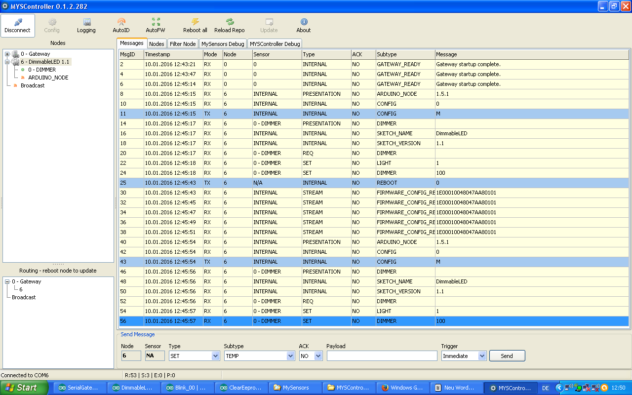
here is the log. Contains:
[2016-01-10 12:02:26.390 Info] INFO *** Logging START *** // stebra : succesful reboot of node 6 via myscontroller
[2016-01-10 12:02:59.000 Info] INFO *** Logging START *** // stebra : succesful FW update of node 6 via myscontroller
[2016-01-10 12:05:35.109 Info] INFO *** Logging START *** // stebra : ID reassign attempt of node 6 to node 12 via myscontroller
[2016-01-10 12:05:48.328 Info] INFO Send FW info to node 6: type=1E, version=1, blocks=0x0448, CRC=0xA87A // here the behaviour is unexpected for me[2016-01-10 12:06:37.437 Info] INFO *** Logging START *** // stebra: Clear eeprom attempt on node 6
[2016-01-10 12:06:44.812 Info] INFO Send FW info to node 6: type=1E, version=1, blocks=0x0448, CRC=0xA87A // here the behaviour is unexpected for methank you for having a look..
-
Maybe I should open a new topic for this, but I cannot flash bootloader, I always get
Arduino: 1.6.7 (Windows 10), Board: "ATmega328 internal 8Mhz with MYSBootloader"
***failed;
avrdude: verification error, first mismatch at byte 0x0000
0x3f != 0xff
avrdude: verification error; content mismatch
Error while burning bootloader.Here is the verbose message
C:\Program Files (x86)\Arduino\hardware\tools\avr/bin/avrdude -CC:\Program Files (x86)\Arduino\hardware\tools\avr/etc/avrdude.conf -v -patmega328p -cstk500v1 -PCOM4 -b19200 -Uflash:w:C:\Program Files (x86)\Arduino\hardware\arduino\avr/bootloaders/MySensors/MYSBootloader.hex:i -Ulock:w:0xFF:m
Reading | ################################################## | 100% 0.01s

avrdude: verifying ...
avrdude: 1 bytes of lock verified
avrdude: reading input file "0x06"
avrdude: writing efuse (1 bytes):

Writing | ################################################## | 100% 0.01s

avrdude: 1 bytes of efuse written
avrdude: verifying efuse memory against 0x06:
avrdude: load data efuse data from input file 0x06:
avrdude: input file 0x06 contains 1 bytes
avrdude: reading on-chip efuse data:

Reading | ################################################## | 100% 0.01s

avrdude: verifying ...
avrdude: 1 bytes of efuse verified
avrdude: reading input file "0xDA"
avrdude: writing hfuse (1 bytes):

Writing | ################################################## | 100% 0.01s

avrdude: 1 bytes of hfuse written
avrdude: verifying hfuse memory against 0xDA:
avrdude: load data hfuse data from input file 0xDA:
avrdude: input file 0xDA contains 1 bytes
avrdude: reading on-chip hfuse data:

Reading | ################################################## | 100% 0.01s

avrdude: verifying ...
avrdude: 1 bytes of hfuse verified
avrdude: reading input file "0xE2"
avrdude: writing lfuse (1 bytes):

Writing | ################################################## | 100% 0.01s

avrdude: 1 bytes of lfuse written
avrdude: verifying lfuse memory against 0xE2:
avrdude: load data lfuse data from input file 0xE2:
avrdude: input file 0xE2 contains 1 bytes
avrdude: reading on-chip lfuse data:

Reading | ################################################## | 100% 0.01s

avrdude: verifying ..
avrdude: 1 bytes of lfuse verified

avrdude done.  Thank you.


avrdude: Version 6.0.1, compiled on Apr 15 2015 at 19:59:58
         Copyright (c) 2000-2005 Brian Dean, http://www.bdmicro.com/
         Copyright (c) 2007-2009 Joerg Wunsch

         System wide configuration file is "C:\Program Files (x86)\Arduino\hardware\tools\avr/etc/avrdude.conf"

         Using Port                    : COM4
         Using Programmer              : stk500v1
         Overriding Baud Rate          : 19200
         AVR Part                      : ATmega328P
         Chip Erase delay              : 9000 us
         PAGEL                         : PD7
         BS2                           : PC2
         RESET disposition             : dedicated
         RETRY pulse                   : SCK
         serial program mode           : yes
         parallel program mode         : yes
         Timeout                       : 200
         StabDelay                     : 100
         CmdexeDelay                   : 25
         SyncLoops                     : 32
         ByteDelay                     : 0
         PollIndex                     : 3
         PollValue                     : 0x53
         Memory Detail                 :

                                  Block Poll               Page                       Polled
           Memory Type Mode Delay Size  Indx Paged  Size   Size #Pages MinW  MaxW   ReadBack
           ----------- ---- ----- ----- ---- ------ ------ ---- ------ ----- ----- ---------
           eeprom        65    20     4    0 no       1024    4      0  3600  3600 0xff 0xff
           flash         65     6   128    0 yes     32768  128    256  4500  4500 0xff 0xff
           lfuse          0     0     0    0 no          1    0      0  4500  4500 0x00 0x00
           hfuse          0     0     0    0 no          1    0      0  4500  4500 0x00 0x00
           efuse          0     0     0    0 no          1    0      0  4500  4500 0x00 0x00
           lock           0     0     0    0 no          1    0      0  4500  4500 0x00 0x00
           calibration    0     0     0    0 no          1    0      0     0     0 0x00 0x00
           signature      0     0     0    0 no          3    0      0     0     0 0x00 0x00

         Programmer Type : STK500
         Description     : Atmel STK500 Version 1.x firmware
         Hardware Version: 2
         Firmware Version: 1.18
         Topcard         : Unknown
         Vtarget         : 0.0 V
         Varef           : 0.0 V
         Oscillator      : Off
         SCK period      : 0.1 us
avrdude: AVR device initialized and ready to accept instructions

Reading | ################################################## | 100% 0.02s

avrdude: Device signature = 0x1e950f
avrdude: NOTE: "flash" memory has been specified, an erase cycle will be performed
         To disable this feature, specify the -D option.
avrdude: erasing chip
avrdude: reading input file "C:\Program Files (x86)\Arduino\hardware\arduino\avr/bootloaders/MySensors/MYSBootloader.hex"
avrdude: writing flash (32722 bytes):

Writing | ################################################## | 100% 0.00s

avrdude: 32722 bytes of flash written
avrdude: verifying flash memory against C:\Program Files (x86)\Arduino\hardware\arduino\avr/bootloaders/MySensors/MYSBootloader.hex:
avrdude: load data flash data from input file C:\Program Files (x86)\Arduino\hardware\arduino\avr/bootloaders/MySensors/MYSBootloader.hex:
avrdude: input file C:\Program Files (x86)\Arduino\hardware\arduino\avr/bootloaders/MySensors/MYSBootloader.hex contains 32722 bytes
avrdude: reading on-chip flash data:

Reading | ################################################## | 100% -0.00s

avrdude: verifying ...
avrdude: 32722 bytes of flash verified
avrdude: reading input file "0xFF"
avrdude: writing lock (1 bytes):

Error while burning bootloader.
Writing |  ***failed;
################################################## | 100% 0.07s

avrdude: 1 bytes of lock written
avrdude: verifying lock memory against 0xFF:
avrdude: load data lock data from input file 0xFF:
avrdude: input file 0xFF contains 1 bytes
avrdude: reading on-chip lock data:

Reading | ################################################## | 100% 0.01s

avrdude: verifying ...
avrdude: verification error, first mismatch at byte 0x0000
         0x3f != 0xff
avrdude: verification error; content mismatch

avrdude done.  Thank you.
I get same message with both 3.3v and 5v pro mini that is linked in the store.
I am using Funduino uno as a ips, and I can flash blink f.eks. using uno as isp, but I cannot flash bootloader. This is the step 6 from the instructions that is failing. Any ideas how to fix this? I would really like OTA as my network is slowly growing.
Thanks for any tips! -
I think I have flashed MYSBootloader finaly, after ~6hours of trying and reading (persistent guy :) )
The instructions are for the older version I guess, right board should be copied from MYSController/bootloader/boards.txt, not from this topic post#75. Now I am trying to figure how to flash the sketch, but I guess that is explained somewhere on the topic -
Just one more question, I didn't find it answered on the topic (maybe too tired), but:
I have existing network with ethernet gateway and some nodes, and all is working fine. To make it OTA update-able, I need to- i upload ethernet gateway to the Arduino Nano, then flash MYSBootloader on it,
- upload some sketch (which?) on Arduino Mini nodes, and then flash MYSBootloader on it, and then I can program it OTA?
- Or something else?
Or did I miss the point completely? :(
-
so from what I know.
you DONT need the MYSBootloader on the gateway. just normal arduino bootloader. you DO need the MYSBootloader on ALL the sensors you with to connect to your gateway.
Do the MYSBootloader first then use this tool to upload the firmware to your sensors OTA -
I think I have flashed MYSBootloader finaly, after ~6hours of trying and reading (persistent guy :) )
The instructions are for the older version I guess, right board should be copied from MYSController/bootloader/boards.txt, not from this topic post#75. Now I am trying to figure how to flash the sketch, but I guess that is explained somewhere on the topic@dakipro I use the settings mentioned in #75 in Atmel studio, however, AVRDUDE does not support the upper two bits of the lock fuse (therefore the error message 0xFF!=0x3F). Changing the lock bits to 0x3F should do the job.
And yes, as @p0lar pointed out, only the nodes and not the gateway should have MYSBootloader.
-
Aha, I get it now. Then I just flash MYSBootloader on the sensor, and attach the radio and it will automatically connect to the gateway (it has some sort of sketch/communication with MySensors built in)? And then I use the MYSController to upload my sketch as described?
Or how do I upload a initial sketch if I cannot use arduino anymore?
Btw, I love MYSController, i use it all the time in development as it shows all that is going on with the sensors, thank you very much for developing it!
-
correct. you build the .hex file in arduino studio or whatever and copy it to the MY gui firmware folder and edit the csv file and then reload.
http://forum.mysensors.org/topic/1066/bootloader/8
This should help
-
I thinking I am build a DEBUG version of the GW code. but I dont think the logging is working in the app with my eth GW. am I mising something?
So. when I build a DEBUG version of the GW code I get this in the serial console hex size=29k so its bigger.
0;0;3;0;9;gateway started, id=0, parent=0, distance=0
0;0;3;0;9;read: 1-1-0 s=1,c=1,t=0,pt=7,l=5,sg=0:71.6
1;1;1;0;0;71.6
0;0;3;0;9;read: 2-2-0 s=1,c=1,t=16,pt=0,l=1,sg=0:0
2;1;1;0;16;0the NON DEBUG I get this. hex size = 26k
1;1;1;0;0;69.8
1;0;1;0;1;35.0
1;1;1;0;0;71.6
1;0;1;0;1;36.0
1;1;1;0;0;73.4
1;0;1;0;1;37.0
2;1;1;0;16;0 -
I thinking I am build a DEBUG version of the GW code. but I dont think the logging is working in the app with my eth GW. am I mising something?
So. when I build a DEBUG version of the GW code I get this in the serial console hex size=29k so its bigger.
0;0;3;0;9;gateway started, id=0, parent=0, distance=0
0;0;3;0;9;read: 1-1-0 s=1,c=1,t=0,pt=7,l=5,sg=0:71.6
1;1;1;0;0;71.6
0;0;3;0;9;read: 2-2-0 s=1,c=1,t=16,pt=0,l=1,sg=0:0
2;1;1;0;16;0the NON DEBUG I get this. hex size = 26k
1;1;1;0;0;69.8
1;0;1;0;1;35.0
1;1;1;0;0;71.6
1;0;1;0;1;36.0
1;1;1;0;0;73.4
1;0;1;0;1;37.0
2;1;1;0;16;0@p0lar said:
So. when I build a DEBUG version of the GW code I get this in the serial console hex size=29k so its bigger.
0;0;3;0;9;gateway started, id=0, parent=0, distance=0
0;0;3;0;9;read: 1-1-0 s=1,c=1,t=0,pt=7,l=5,sg=0:71.6
1;1;1;0;0;71.6
0;0;3;0;9;read: 2-2-0 s=1,c=1,t=16,pt=0,l=1,sg=0:0
2;1;1;0;16;0that looks good :)
Hello! It looks like you're interested in this conversation, but you don't have an account yet.
Getting fed up of having to scroll through the same posts each visit? When you register for an account, you'll always come back to exactly where you were before, and choose to be notified of new replies (either via email, or push notification). You'll also be able to save bookmarks and upvote posts to show your appreciation to other community members.
With your input, this post could be even better 💗
Register Login