💬 Various bootloader files based on Optiboot 6.2
-
@GertSanders Unfortunately, I was able to upload the bootloader, but was not able to upload any sketches on the breadboard:
avrdude: stk500_getsync() attempt 1 of 10: not in sync: resp=0x78
avrdude: stk500_getsync() attempt 2 of 10: not in sync: resp=0xc0
avrdude: stk500_getsync() attempt 3 of 10: not in sync: resp=0x78
Not sure why - I can upload a sketch via the programmer though. Will upload Nick Gammon sketch to test the bootloader.
UPDATE1: Nick Gammon's sketch cannot detect the bootloader (tried 1MHz internal). Once again, I uploaded the bootloader (1Mhz internal) and the sketch via the programmer and it works, but....the serial monitor works only on 74880, despite for "1Mhz internal" boards.txt clearly says "9600":
BlueBoard.menu.mhz.1Mi= 1Mhz - internal - 9K6 upload speed
BlueBoard.menu.mhz.1Mi.bootloader.low_fuses=0xE2
BlueBoard.menu.mhz.1Mi.bootloader.high_fuses=0xDE
BlueBoard.menu.mhz.1Mi.build.f_cpu=1000000L
BlueBoard.menu.mhz.1Mi.upload.speed=9600
BlueBoard.menu.mhz.1Mi.bootloader.file=myoptiboot/optiboot_atmega328_01M_009600_B0.hex
Additionally, I loaded the ASCIITable example sketch and it states " Serial.begin(9600);"
I do not understand why it works only on 74880...I will do some testing tonight, I have not used the 1MHz bootloader yet.
The instruction Serial.begin(9600) is independant of the upload.speed mentioned in the boards file. But I would expect that at 1MHz the higher serial comms speeds also give errors.
A possible reason for the problem, is that the fuse E2 actually means that you run the processor at 8Mhz internally, but without any clock division, while the bootloader was compiled for 1MHz. Without clock division by 8 the processor actually runs at 8Mhz (the speed of the internal oscillator), while all timing code is set for a cpu working frequency of 1Mhz. This would also explain why you can communicate at 74880 (which is close to 76800, which in turn is 8 times 9600).
I think the fuse should be set to both internal 8MHz oscillator AND clock division by 8. I do not know that correct value by hart, need to check that with a fuse calculator.
UPDATE: I think the lower fuse should be set to 0x62 instead of 0xE2.
-
OK, I have come to the following fuse settings for 1Mhz internal:
BlueBoard.menu.mhz.1Mi.bootloader.low_fuses=0x62
BlueBoard.menu.mhz.1Mi.bootloader.high_fuses=0xDE
For Optiboot, the high fuse is always 0xDE.
Now, a standard example sketch runs at 9600 - I have not checked if atmega328p is running at 1Mhz.Still have a problem uploading a sketch on the breadboard via FTDI
I will do some tests later tonight.
-
OK, I have come to the following fuse settings for 1Mhz internal:
BlueBoard.menu.mhz.1Mi.bootloader.low_fuses=0x62
BlueBoard.menu.mhz.1Mi.bootloader.high_fuses=0xDE
For Optiboot, the high fuse is always 0xDE.
Now, a standard example sketch runs at 9600 - I have not checked if atmega328p is running at 1Mhz.Still have a problem uploading a sketch on the breadboard via FTDI
I just loaded a blink sketch at 4800 baud using FTDI and that works with the following combination:
Boot loader:
0_1457554985438_optiboot_atmega328_08M1_004800_B0.hexFuses:
BlueBoard.menu.mhz.1Mi48= 1Mhz - internal 8MHz DIV 8 - 4K8 upload speed
BlueBoard.menu.mhz.1Mi48.bootloader.low_fuses=0x62
BlueBoard.menu.mhz.1Mi48.bootloader.high_fuses=0xDE
BlueBoard.menu.mhz.1Mi48.build.f_cpu=1000000L
BlueBoard.menu.mhz.1Mi48.upload.speed=4800
BlueBoard.menu.mhz.1Mi48.bootloader.file=myoptiboot/optiboot_atmega328_08M1_004800_B0.hexYou will have to strip the "0_1457554985438_" part from the uploaded filename.
Loading the sketch is VERY slow, but it works perfectly. The Blink sketch blinks the led at 500ms on and 500ms off, and that is checked on the breadboard.
Whether the processor actually runs at 1MHz I do not know for sure, since I have no frequency meter (still missing from my toolbox).
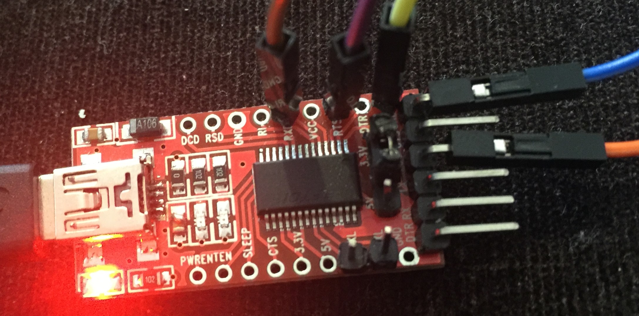
I used an arduino as ISP to load the boot loader, and then used an FTDI interface (from Adafruit) to load the sketch while the atmega328 was plugged in a breadboard (Gammon style).
Next I will try with the 9600 baud version at 1Mhz.
-
I just loaded a blink sketch at 4800 baud using FTDI and that works with the following combination:
Boot loader:
0_1457554985438_optiboot_atmega328_08M1_004800_B0.hexFuses:
BlueBoard.menu.mhz.1Mi48= 1Mhz - internal 8MHz DIV 8 - 4K8 upload speed
BlueBoard.menu.mhz.1Mi48.bootloader.low_fuses=0x62
BlueBoard.menu.mhz.1Mi48.bootloader.high_fuses=0xDE
BlueBoard.menu.mhz.1Mi48.build.f_cpu=1000000L
BlueBoard.menu.mhz.1Mi48.upload.speed=4800
BlueBoard.menu.mhz.1Mi48.bootloader.file=myoptiboot/optiboot_atmega328_08M1_004800_B0.hexYou will have to strip the "0_1457554985438_" part from the uploaded filename.
Loading the sketch is VERY slow, but it works perfectly. The Blink sketch blinks the led at 500ms on and 500ms off, and that is checked on the breadboard.
Whether the processor actually runs at 1MHz I do not know for sure, since I have no frequency meter (still missing from my toolbox).
I used an arduino as ISP to load the boot loader, and then used an FTDI interface (from Adafruit) to load the sketch while the atmega328 was plugged in a breadboard (Gammon style).
Next I will try with the 9600 baud version at 1Mhz.
@GertSanders said:
Next I will try with the 9600 baud version at 1Mhz.
THanks
I'm looking forward to this - 4800 is way too slow.
I think the way to check the frequency is to time delay(1000); in the blink sketch... -
@GertSanders said:
Next I will try with the 9600 baud version at 1Mhz.
THanks
I'm looking forward to this - 4800 is way too slow.
I think the way to check the frequency is to time delay(1000); in the blink sketch...I just tested with the 9600 baud version at 1MHz, and the blink sketch at 250ms, 500ms and 1000ms per on/off cycle. All rock solid and as expected.
Here is the setup I tested the transfer with FTDI:
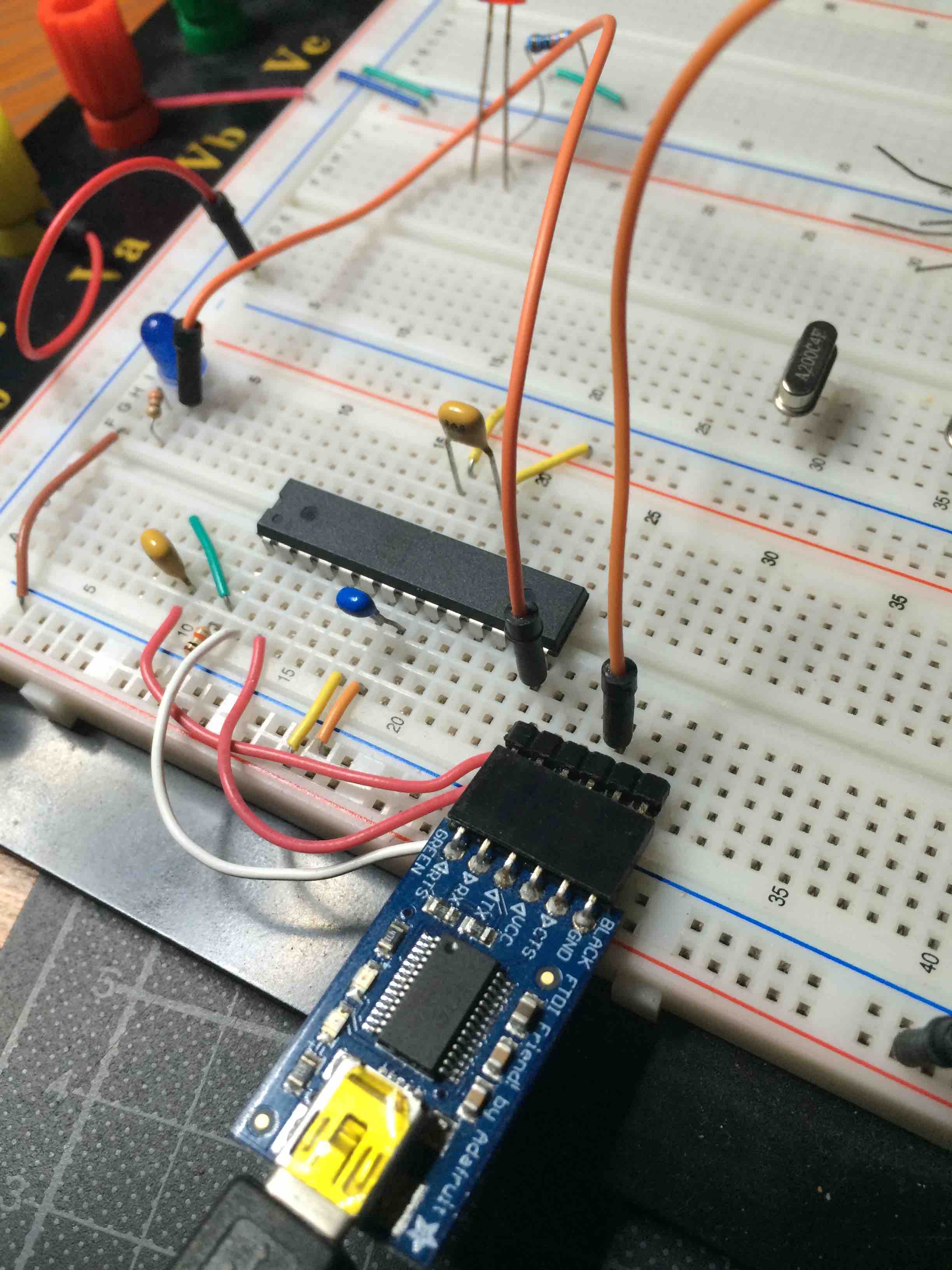
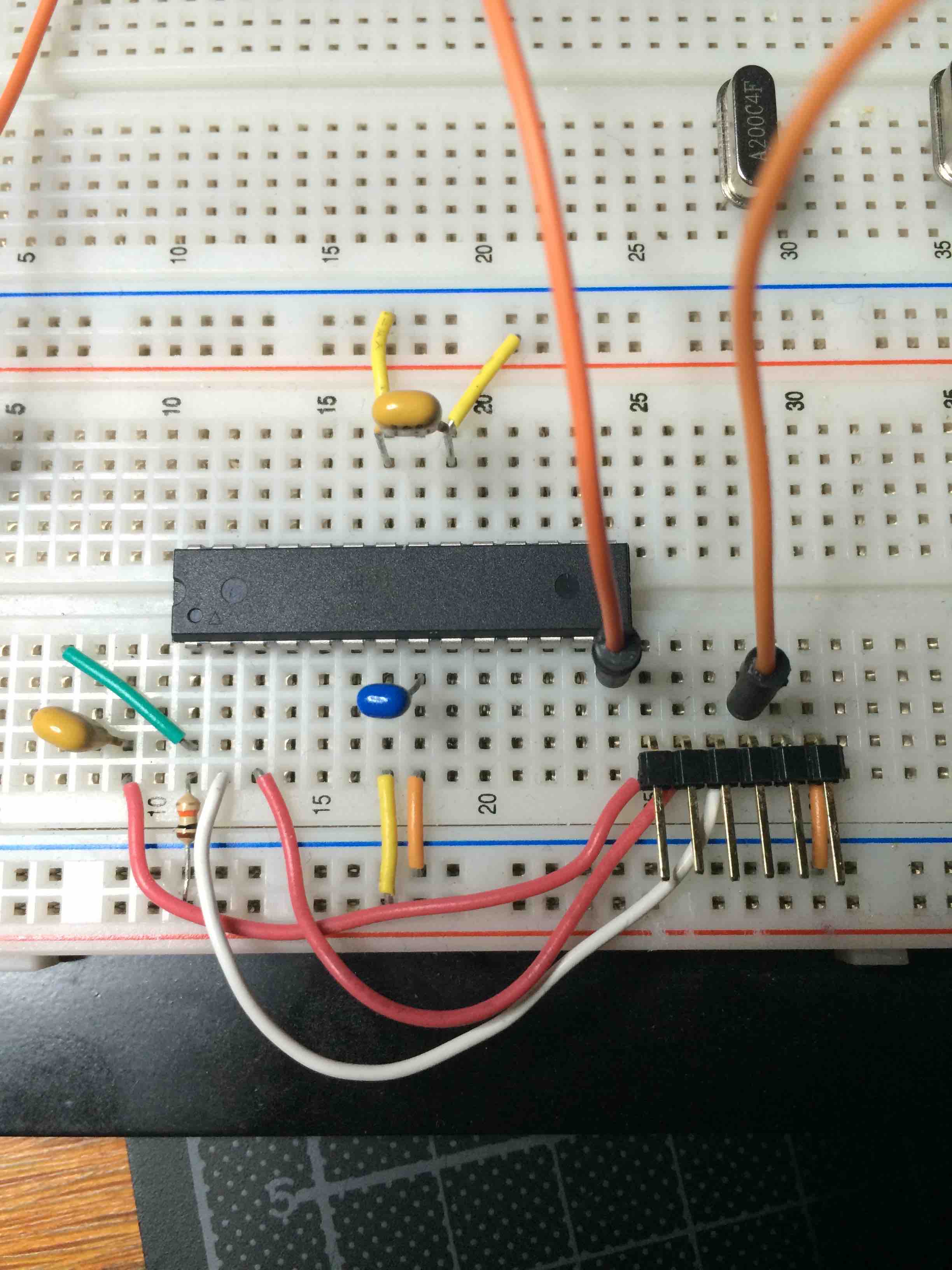
I used the following combination:
Boot loader:
0_1457556618255_optiboot_atmega328_01M_009600_B0.hex
Fuses:
BlueBoard.menu.mhz.1Mi= 1Mhz - internal 8MHz DIV 8 - 9K6 upload speed
BlueBoard.menu.mhz.1Mi.bootloader.low_fuses=0x62
BlueBoard.menu.mhz.1Mi.bootloader.high_fuses=0xDE
BlueBoard.menu.mhz.1Mi.build.f_cpu=1000000L
BlueBoard.menu.mhz.1Mi.upload.speed=9600
BlueBoard.menu.mhz.1Mi.bootloader.file=myoptiboot/optiboot_atmega328_01M_009600_B0.hexAlso here the "0_1457556618255_" is added by uploading on this forum, strip when downloaded.
Uploads were at twice the speed then before. Still slow, but acceptable.
-
@GertSanders I have the same breadboard setup, but can only read serial and cannot upload a sketch (out of sync). My settings are the same as yours as per my post earlier on today so I reckon it must be something wrong with the wiring on the breadboard since "Uploading using Programmer" works fine. Not sure what it is as I checked it a few times today.
@alexsh1
Maybe make a picture of your setup?
Upload using programmer means you use another Arduino to load the sketch on the atmega328, which at the same time deletes any bootloader.
I load bootloaders with an Arduino and the sketch ArduinoISP loaded on that one. Then I issue a "burn bootloader" command.
To load sketches I switch to my FTDI interface and upload sketches with the same processor setting. But as said with a different interface. And I do not use "upload using programmer", but the upload button next to the compile button.Maybe I should try to make a video like Mr Pete.
-
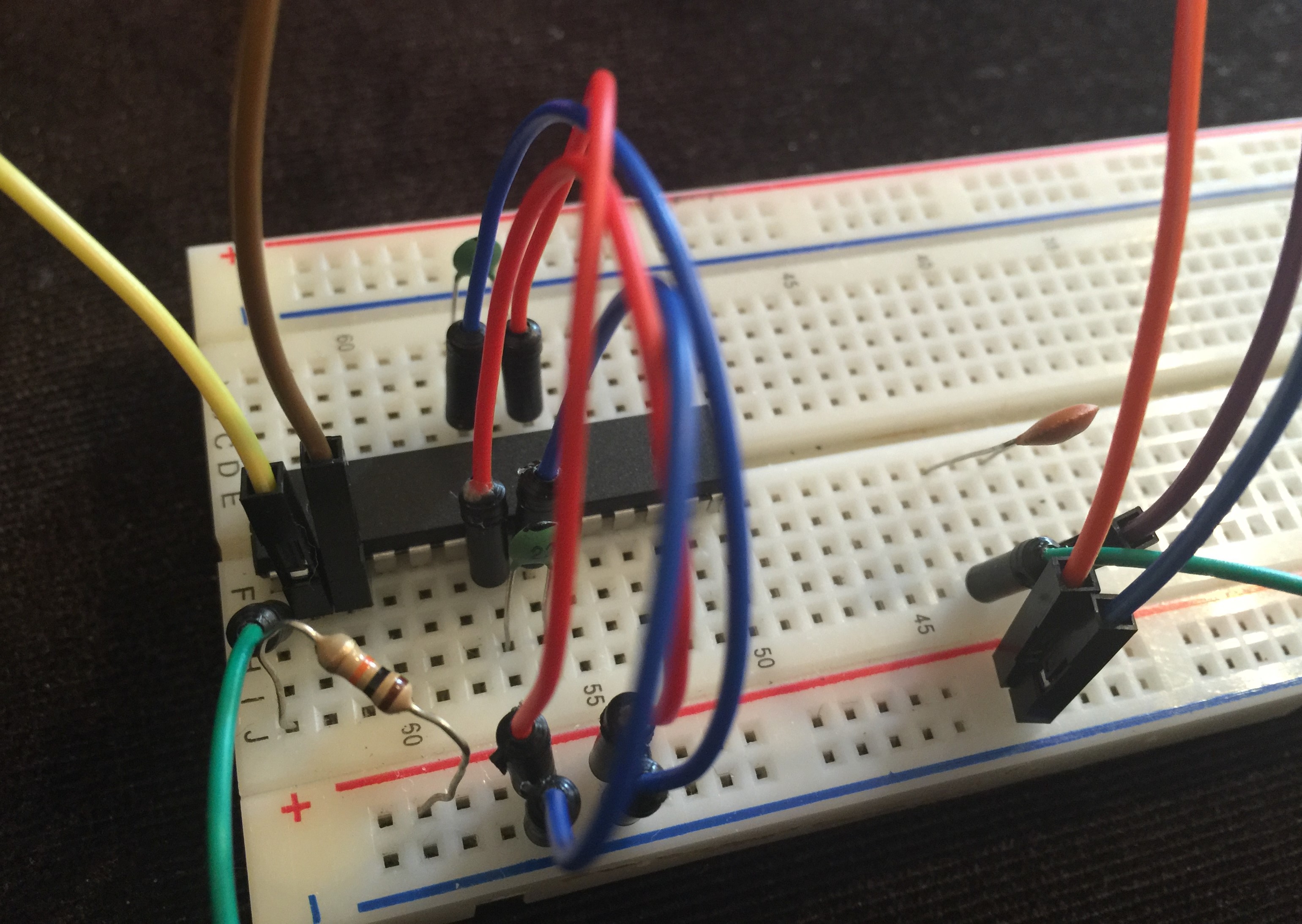
@GertSanders Yes, this is normally the way I do (burn bootloader and then upload a sketch via FTDI on the breadboard). Will post photos shortly.
Are you sure "Upload using programmer" deleting the bootloader?
Are you sure "Upload using programmer" deleting the bootloader?
Yes, looks like you are right - it kills the bootloader. So what's happening? I do not have any bootloader when I use this method to load up sketches?
-
Are you sure "Upload using programmer" deleting the bootloader?
Yes, looks like you are right - it kills the bootloader. So what's happening? I do not have any bootloader when I use this method to load up sketches?
If you load a sketch with "Upload using programmer" you replace anything in flash with the sketch. Just the sketch will run on the mcu.
In the very narrow node, there is no FTDI connector, so for those nodes it does not make sense to have a boot loader in flash (it does not hurt either). You couldvjust as well just load the sketch and skip the boot loader altogether.
If you need the extra 512 that optiboot occupies, then "Upload using programmer" allows you to recuperate that space.
So this shoudl explain why you can reed data from the Node via Serial (because the sketch is running and taking care of the serial connection), but why uploading a sketch fails, because for that you need a boot loader in flash.
-
I did a short video how I upload optiboot
Finally, success!
I think I had to reassemble the breadboard set-up three times before finally being able to upload the sketch. I think the problem was no connection at RTS, but I am not sure. I need to assemble a more permanent board to upload sketches via FTDI. -
@GertSanders if I load a sketch via Upload using programmer - how do I control the frequency? (1Mhz or 8Mhz internal or external crystal)
-
@GertSanders if I load a sketch via Upload using programmer - how do I control the frequency? (1Mhz or 8Mhz internal or external crystal)
@alexsh1 - You would do this by setting the correct fuses. Can you just confirm my information @GertSanders :)
I would also like to state that Atmel does not support or even recommend using FTDI with the internal crystal, my current board just will not upload via FTDI and no external crystal however yet a arduino pro mini does and that uses an external crystal with no other circuitry compared to my board apart from the physical reset switch.
MySensors 2.1.1
Controller - OpenHAB (Virtual Machine)
Gateway - Arduino Mega MQTT Gateway W5100 -
@alexsh1 - You would do this by setting the correct fuses. Can you just confirm my information @GertSanders :)
I would also like to state that Atmel does not support or even recommend using FTDI with the internal crystal, my current board just will not upload via FTDI and no external crystal however yet a arduino pro mini does and that uses an external crystal with no other circuitry compared to my board apart from the physical reset switch.
@samuel235 said:
@alexsh1 - You would do this by setting the correct fuses. Can you just confirm my information @GertSanders :)
I think you have a point, but if I do not change anything, just use "Upload using programmer", what are the default frequency and fuses?
-
@samuel235 said:
@alexsh1 - You would do this by setting the correct fuses. Can you just confirm my information @GertSanders :)
I think you have a point, but if I do not change anything, just use "Upload using programmer", what are the default frequency and fuses?
@alexsh1 If you haven't touched the ATmega328p then it should be sitting with fuses of; L:0x62 H:0xD9 E:0xFF, which would run the uC at 1MHz
-
@samuel235 said:
@alexsh1 - You would do this by setting the correct fuses. Can you just confirm my information @GertSanders :)
I think you have a point, but if I do not change anything, just use "Upload using programmer", what are the default frequency and fuses?
@*alexsh1
*
Which fuses are set when loading a boot loader is defined by wich menu element in tools you have selected. Every processor or board you choose will correspond with values in a board.txt file.You can have several board.txt files: 1 file per "family" of boards.
When uploading sketches, the fusesettings are ignored, only the uploadspeed counts then. Both when uploading with Arduino as ISP as with FTDI interface.
The internal oscillator of 8 Mhz is not as accurate as a crystal, so at higher uploadspeeds the errorrate can increase or decrease depending on the mcu temperature.
Some uploadspeeds are closer to optimal then others in relation to the frequency at which the mcu works. The baudcalculator shows the errorrates. Most are non optimal. avrdude can handle an errorrate of 2% or less. So using a specific baudrate in combination with the internal 8Mhz oscillator depends on the worst case combination of transmission errorrate plus clock deviation error.
For most mcu's the rate of 9600 baud will be acceptable because at that slow rate a clockerror will be relative small. At higher speeds the small clockerror becomes more important. Then it is best to choose an upload speed close to the optimum.
The fusesettings are only burnt when loading a boot loader (within the Arduino IDE, in AVRStudio you can set fuses seperatly from loading anything).
The frequency of 8 Mhz can be obtained via a 8mhz crystal or the internal 8mhz oscillator. The low fuse value 0xE2 sets this internal oscillator. By using value 0x62 you also set the clock division bit in combination with the 8mhz internal oscillator, so your mcu will run at 8mhz / 8 = 1mhz
There are other division values possible. Calculate the low byte value using an avr fuse calculator.
You can also use an external 8 mhz crystal, and combine this with clock division by 8 to get 1mhz operation.
And you can choose an external 1mhz crystal.
All this from choose the right fuse bits.
Same for Brown out Detection which is set via the three least significant bits of the extended fuse.
-
@alexsh1 If you haven't touched the ATmega328p then it should be sitting with fuses of; L:0x62 H:0xD9 E:0xFF, which would run the uC at 1MHz
@samuel235 This is strange. The serial monitor was working only on 74880 - I do not think the AVR was running @ 1Mhz
Hello! It looks like you're interested in this conversation, but you don't have an account yet.
Getting fed up of having to scroll through the same posts each visit? When you register for an account, you'll always come back to exactly where you were before, and choose to be notified of new replies (either via email, or push notification). You'll also be able to save bookmarks and upvote posts to show your appreciation to other community members.
With your input, this post could be even better 💗
Register Login