Skip to content
  • MySensors
  • OpenHardware.io
  • Categories
  • Recent
  • Tags
  • Popular
Skins
  • Light
  • Brite
  • Cerulean
  • Cosmo
  • Flatly
  • Journal
  • Litera
  • Lumen
  • Lux
  • Materia
  • Minty
  • Morph
  • Pulse
  • Sandstone
  • Simplex
  • Sketchy
  • Spacelab
  • United
  • Yeti
  • Zephyr
  • Dark
  • Cyborg
  • Darkly
  • Quartz
  • Slate
  • Solar
  • Superhero
  • Vapor

  • Default (No Skin)
  • No Skin
Collapse
Brand Logo
  1. Home
  2. KiCad
  3. NRF24L01+ smd schematics

NRF24L01+ smd schematics

Scheduled Pinned Locked Moved KiCad
18 Posts 5 Posters 10.8k Views 4 Watching
  • Oldest to Newest
  • Newest to Oldest
  • Most Votes
Reply
  • Reply as topic
Log in to reply
This topic has been deleted. Only users with topic management privileges can see it.
  • alexsh1A Offline
    alexsh1A Offline
    alexsh1
    wrote on last edited by alexsh1
    #7

    @GertSanders you can change the status of your node as "tested". It works just fine - one important thing to remember is to solder the 3.3v solderpad. A couple of observations:

    1. I can no longer fit a single AAA battery holders, but a double one only (AA or AAA)

    2. the holes for J1 are two small and I had to drill them out.

    I have not tested ATSHA204A as I do not have all components yet.

    GertSandersG 1 Reply Last reply
    0
    • alexsh1A alexsh1

      @GertSanders you can change the status of your node as "tested". It works just fine - one important thing to remember is to solder the 3.3v solderpad. A couple of observations:

      1. I can no longer fit a single AAA battery holders, but a double one only (AA or AAA)

      2. the holes for J1 are two small and I had to drill them out.

      I have not tested ATSHA204A as I do not have all components yet.

      GertSandersG Offline
      GertSandersG Offline
      GertSanders
      Hardware Contributor
      wrote on last edited by GertSanders
      #8

      @alexsh1

      So you received the boards before I did :-)

      I'm still waiting on them. They are "in the mail" or at least in the hands of my local mail service (any day now...).

      Which type of header/connector did you use to mount in the J1 location ? If the holes are too narrow for the breakable two row male headers, I will adapt this (that is why it is still UNTESTED for me).

      Indeed, one or two single AAA holders are not possible on this board. I found that the double battery holders actually are cheaper, and it allows avoiding two extra holes where the radio now sits.

      Update: I checked the drill size of the part used in v3 to place the header, indeed this is 0,8mm (31 mil) instead of 1,016mm (40 mil).
      In my v4 version I already switched to a wider header, and this one does have 40 mil drill diameter. It's good I did not do a panel with the v3 version.

      alexsh1A 1 Reply Last reply
      0
      • GertSandersG GertSanders

        @alexsh1

        So you received the boards before I did :-)

        I'm still waiting on them. They are "in the mail" or at least in the hands of my local mail service (any day now...).

        Which type of header/connector did you use to mount in the J1 location ? If the holes are too narrow for the breakable two row male headers, I will adapt this (that is why it is still UNTESTED for me).

        Indeed, one or two single AAA holders are not possible on this board. I found that the double battery holders actually are cheaper, and it allows avoiding two extra holes where the radio now sits.

        Update: I checked the drill size of the part used in v3 to place the header, indeed this is 0,8mm (31 mil) instead of 1,016mm (40 mil).
        In my v4 version I already switched to a wider header, and this one does have 40 mil drill diameter. It's good I did not do a panel with the v3 version.

        alexsh1A Offline
        alexsh1A Offline
        alexsh1
        wrote on last edited by
        #9

        @GertSanders

        So you received the boards before I did :-)

        Yes, I have got the boards in 3-4 days. Very quick

        Which type of header/connector did you use to mount in the J1 location ? If the holes are too narrow for the breakable two row male headers, I will adapt this (that is why it is still UNTESTED for me).

        I have used a single row header like this
        http://www.protostack.com/connectors/headers/40-pin-2.54mm-snappable-single-row-header

        GertSandersG 1 Reply Last reply
        0
        • alexsh1A alexsh1

          @GertSanders

          So you received the boards before I did :-)

          Yes, I have got the boards in 3-4 days. Very quick

          Which type of header/connector did you use to mount in the J1 location ? If the holes are too narrow for the breakable two row male headers, I will adapt this (that is why it is still UNTESTED for me).

          I have used a single row header like this
          http://www.protostack.com/connectors/headers/40-pin-2.54mm-snappable-single-row-header

          GertSandersG Offline
          GertSandersG Offline
          GertSanders
          Hardware Contributor
          wrote on last edited by
          #10

          @alexsh1
          Ordered from OSHPark ?

          alexsh1A 1 Reply Last reply
          0
          • GertSandersG GertSanders

            @alexsh1
            Ordered from OSHPark ?

            alexsh1A Offline
            alexsh1A Offline
            alexsh1
            wrote on last edited by
            #11

            @GertSanders said:

            @alexsh1
            Ordered from OSHPark ?

            Yes - these guys are good

            1 Reply Last reply
            0
            • E Offline
              E Offline
              emc2
              Hardware Contributor
              wrote on last edited by
              #12

              Did anyone successfully used kicad footprint for these guys?
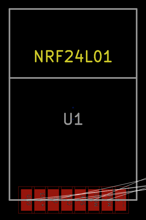
              I received today my first PCB designed for the SMD version, did not work and overheated quite badly. After trying to troubleshoot it, frying a few things on the way, it seems to me that VCC / GND pad are switched between schematics and footprint:

              "Datasheet" from one of many aliexpress / ebay seller (all seems to be the same)
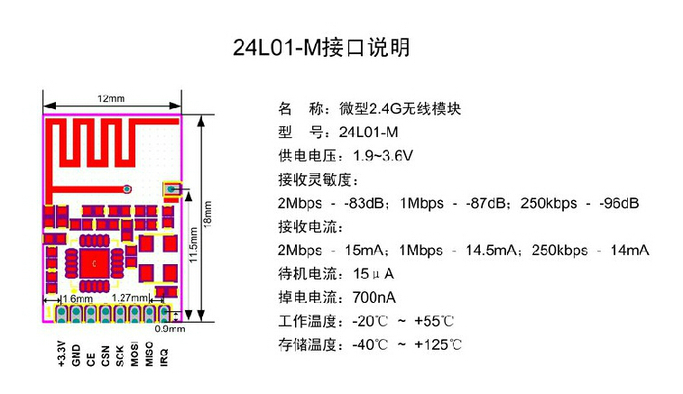
              0_1464483528132_data-smdnrf.jpg

              KiCad PCB view
              0_1464483533073_kicad-smdnrf.png

              I changed it on a local lib to reorder a new PCB and try, but if others can have a look at it, especially @tbowmo to update the official github repo if needed.

              alexsh1A 1 Reply Last reply
              0
              • E emc2

                Did anyone successfully used kicad footprint for these guys?
                I received today my first PCB designed for the SMD version, did not work and overheated quite badly. After trying to troubleshoot it, frying a few things on the way, it seems to me that VCC / GND pad are switched between schematics and footprint:

                "Datasheet" from one of many aliexpress / ebay seller (all seems to be the same)
                0_1464483528132_data-smdnrf.jpg

                KiCad PCB view
                0_1464483533073_kicad-smdnrf.png

                I changed it on a local lib to reorder a new PCB and try, but if others can have a look at it, especially @tbowmo to update the official github repo if needed.

                alexsh1A Offline
                alexsh1A Offline
                alexsh1
                wrote on last edited by alexsh1
                #13

                @emc2 You have to be careful with these. As I discovered myself recently there are ones with PIN1 and PIN2 as VCC and GND and others with PIN1 and PIN8 as VCC and GND.
                This is not well documented!

                E 1 Reply Last reply
                0
                • alexsh1A alexsh1

                  @emc2 You have to be careful with these. As I discovered myself recently there are ones with PIN1 and PIN2 as VCC and GND and others with PIN1 and PIN8 as VCC and GND.
                  This is not well documented!

                  E Offline
                  E Offline
                  emc2
                  Hardware Contributor
                  wrote on last edited by
                  #14

                  @alexsh1 Damnit...
                  Never encountered a PIN1/PIN8 module yet. Are those with blob? I saw a few modules with black blob, often a big cristal and very cheap but I never ordered them.

                  I have a few of this exact module, it has a datasheet on the website and wiring it as described work on a breadboard.
                  Did you encounter any PIN1 - GND, PIN2 - VCC so far?

                  Problem may be somewhere else, probability that I screwed up my PCB design is high. I will see with the next PCB, with pin switched, if it's working.

                  alexsh1A 1 Reply Last reply
                  0
                  • E emc2

                    @alexsh1 Damnit...
                    Never encountered a PIN1/PIN8 module yet. Are those with blob? I saw a few modules with black blob, often a big cristal and very cheap but I never ordered them.

                    I have a few of this exact module, it has a datasheet on the website and wiring it as described work on a breadboard.
                    Did you encounter any PIN1 - GND, PIN2 - VCC so far?

                    Problem may be somewhere else, probability that I screwed up my PCB design is high. I will see with the next PCB, with pin switched, if it's working.

                    alexsh1A Offline
                    alexsh1A Offline
                    alexsh1
                    wrote on last edited by
                    #15

                    @emc2 Yes, all of my nrf24l01+ smd modules have PIN1 - VCC and PIN2 - GND
                    No idea why chinese are switching pins

                    1 Reply Last reply
                    0
                    • tbowmoT Offline
                      tbowmoT Offline
                      tbowmo
                      Admin
                      wrote on last edited by
                      #16

                      @emc2

                      Sorry about that, it was made in a jiffy one dark night, and I never got around to verify the footprint myself :(

                      I'll update the footprint later today (or you can make a PR on github and change it your self).

                      E 1 Reply Last reply
                      0
                      • tbowmoT tbowmo

                        @emc2

                        Sorry about that, it was made in a jiffy one dark night, and I never got around to verify the footprint myself :(

                        I'll update the footprint later today (or you can make a PR on github and change it your self).

                        E Offline
                        E Offline
                        emc2
                        Hardware Contributor
                        wrote on last edited by
                        #17

                        @tbowmo
                        Hey no worries, it's still a great ressource and so far I used it without any problem.

                        I'm always confused by github when it came to PR etc but it should work. I just switched the coordinates of pad 1 and 2 it should do the trick.

                        Thanks!

                        1 Reply Last reply
                        0
                        • tbowmoT Offline
                          tbowmoT Offline
                          tbowmo
                          Admin
                          wrote on last edited by
                          #18

                          @emc2

                          I updated the footprint on github (and yes, I also chose the easy route, and swapped pins 1 and 2 on the footprint) :)

                          1 Reply Last reply
                          0
                          Reply
                          • Reply as topic
                          Log in to reply
                          • Oldest to Newest
                          • Newest to Oldest
                          • Most Votes


                          6

                          Online

                          11.7k

                          Users

                          11.2k

                          Topics

                          113.1k

                          Posts


                          Copyright 2025 TBD   |   Forum Guidelines   |   Privacy Policy   |   Terms of Service
                          • Login

                          • Don't have an account? Register

                          • Login or register to search.
                          • First post
                            Last post
                          0
                          • MySensors
                          • OpenHardware.io
                          • Categories
                          • Recent
                          • Tags
                          • Popular