Skip to content
  • MySensors
  • OpenHardware.io
  • Categories
  • Recent
  • Tags
  • Popular
Skins
  • Light
  • Brite
  • Cerulean
  • Cosmo
  • Flatly
  • Journal
  • Litera
  • Lumen
  • Lux
  • Materia
  • Minty
  • Morph
  • Pulse
  • Sandstone
  • Simplex
  • Sketchy
  • Spacelab
  • United
  • Yeti
  • Zephyr
  • Dark
  • Cyborg
  • Darkly
  • Quartz
  • Slate
  • Solar
  • Superhero
  • Vapor

  • Default (No Skin)
  • No Skin
Collapse
Brand Logo
  1. Home
  2. Hardware
  3. 12V distribution box - mysensorized!

12V distribution box - mysensorized!

Scheduled Pinned Locked Moved Hardware
22 Posts 4 Posters 4.7k Views 4 Watching
  • Oldest to Newest
  • Newest to Oldest
  • Most Votes
Reply
  • Reply as topic
Log in to reply
This topic has been deleted. Only users with topic management privileges can see it.
  • A Offline
    A Offline
    activemind
    wrote on last edited by
    #1

    Kicked off a thread here about a 12V distribution box. Basically takes input from a 12V power supply and provides 4-5 12V output with a VA display.

    Just got done sending off my first PCB to Itead. Its a RGB LED driver using 12V supply. Once again, a shout out to @Samuel235 for his constant feedback and support during that project! :+1:

    I think it would be cool if we can make this 12V distribution box smarter(MySensor aware). I am thinking of doing a PCB for this so that we can report the current draw on each of the ports and maybe control (on/off) each of the ports remotely too.

    Project in investigation phase currently but I need to keep busy till my other PCB shows up from Itead :-)

    -AM

    1 Reply Last reply
    1
    • A Offline
      A Offline
      activemind
      wrote on last edited by
      #2

      Looking some more into it I am thinking of using ACS713 current sensor for this board.

      But it has just 1 channel and I am going to need multiple of these if I want to do like 4-5 outputs.

      Does anyone know of such chip that is similar but does multiple channels?

      -AM

      1 Reply Last reply
      0
      • A Offline
        A Offline
        activemind
        wrote on last edited by activemind
        #3

        Or maybe ACS712.

        But both of these need Vcc=5V. I was hoping to use a 12V powered IC so that I can reduce some circuitry.

        Nevermind, I would need 5/3.3V for the arduino/NRF anyways so this should not be an issue.

        I still need to findout if there is a multichannel version.

        -AM

        1 Reply Last reply
        0
        • A Offline
          A Offline
          activemind
          wrote on last edited by
          #4

          Thinking out loud here but would it be better if I put connectors for current measurement on the PCB for connecting something like this or should I put the ACS chip on the PCB?

          The advantage of using a module is that populating it can be made optional, so you can jumper it if you dont want it on one of the channels. So it would be possible to have like 4 channel out of 5 that report and 1 that does not.

          Plus the cost of the module and bare chip is the same, so I dont think there is any difference from that point of view.

          -AM

          1 Reply Last reply
          0
          • A Offline
            A Offline
            activemind
            wrote on last edited by
            #5

            Or maybe do 1 for the entire board and forget about per channel. Maybe thats the right approach!

            -AM

            1 Reply Last reply
            0
            • A Offline
              A Offline
              activemind
              wrote on last edited by
              #6

              I need some help from one of the hw guys.

              I have arduino pin driving the gate of a FET like so many other examples.

              I have another signal called Fault which is active low.

              Now I want to and the two signals such that when fault becomes active (becomes 0), the FET is forced off.

              Whats the circuit for that?

              Thanks
              -AM

              A 1 Reply Last reply
              0
              • A activemind

                I need some help from one of the hw guys.

                I have arduino pin driving the gate of a FET like so many other examples.

                I have another signal called Fault which is active low.

                Now I want to and the two signals such that when fault becomes active (becomes 0), the FET is forced off.

                Whats the circuit for that?

                Thanks
                -AM

                A Offline
                A Offline
                activemind
                wrote on last edited by
                #7

                @activemind said:

                I need some help from one of the hw guys.

                I have arduino PWM pin driving the gate of a FET like so many other examples.

                I have another signal called Fault which is active low.

                Now I want to and the two signals such that when fault becomes active (becomes 0), the FET is forced off.

                Whats the circuit for that?

                Thanks
                -AM

                1 Reply Last reply
                0
                • A Offline
                  A Offline
                  activemind
                  wrote on last edited by
                  #8

                  Nevermind, found the answer. Just put another FET in there with fault signal driving the gate.

                  -AM

                  1 Reply Last reply
                  0
                  • A Offline
                    A Offline
                    activemind
                    wrote on last edited by activemind
                    #9

                    So I managed to finish the schematic and and posting it for people to look over.
                    Features:

                    1. 1 input and 6 output - 12V
                    2. Easy hook ups for Voltmeter/Ammeter display.
                    3. Voltage and current draw fed back to arduino as input.
                    4. Hardware based overcurrent protection with latch feature.
                    5. Fault status can be reported back to Controller.
                    6. Switch to turn supply off.
                    7. LED indicators for power on and fault.
                    8. All easy solder through components.
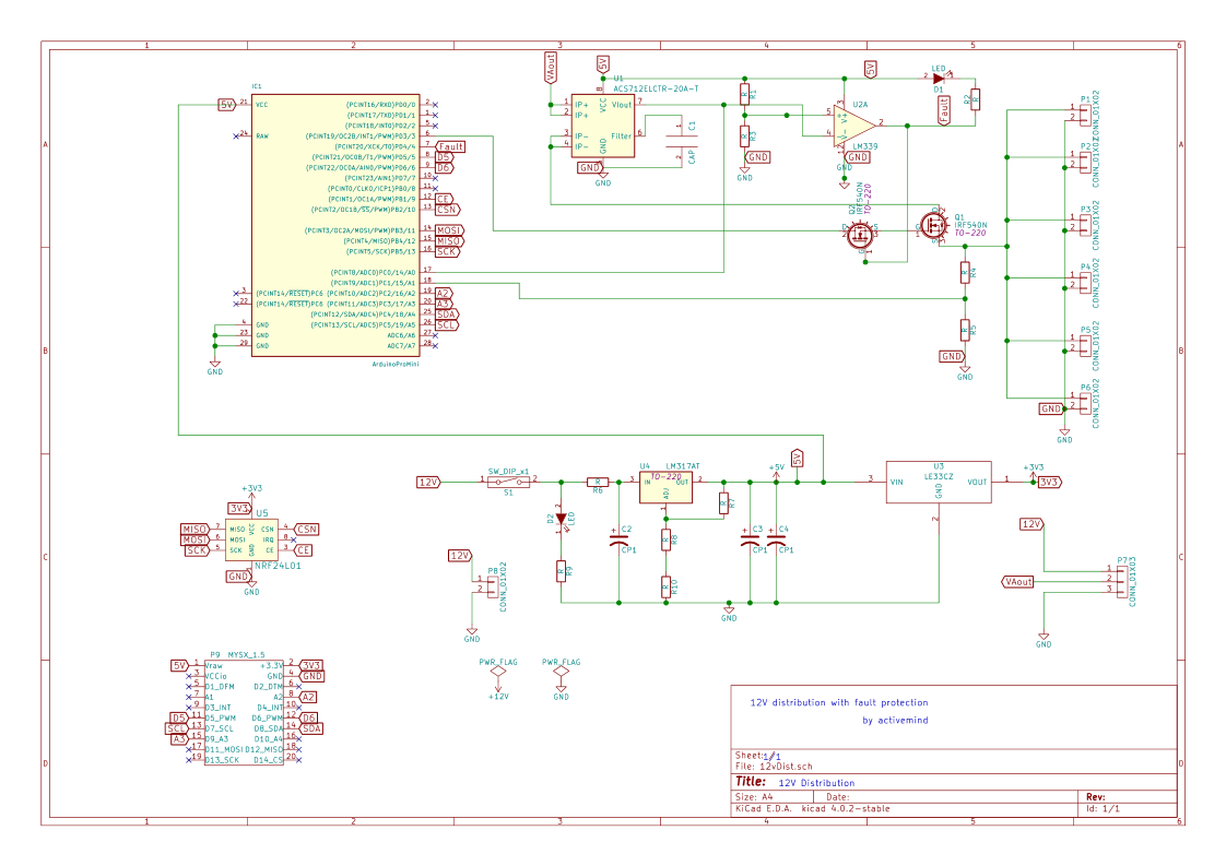
                    0_1466718453270_12vDist.png

                    Comments?

                    -AM

                    1 Reply Last reply
                    0
                    • A Offline
                      A Offline
                      activemind
                      wrote on last edited by
                      #10

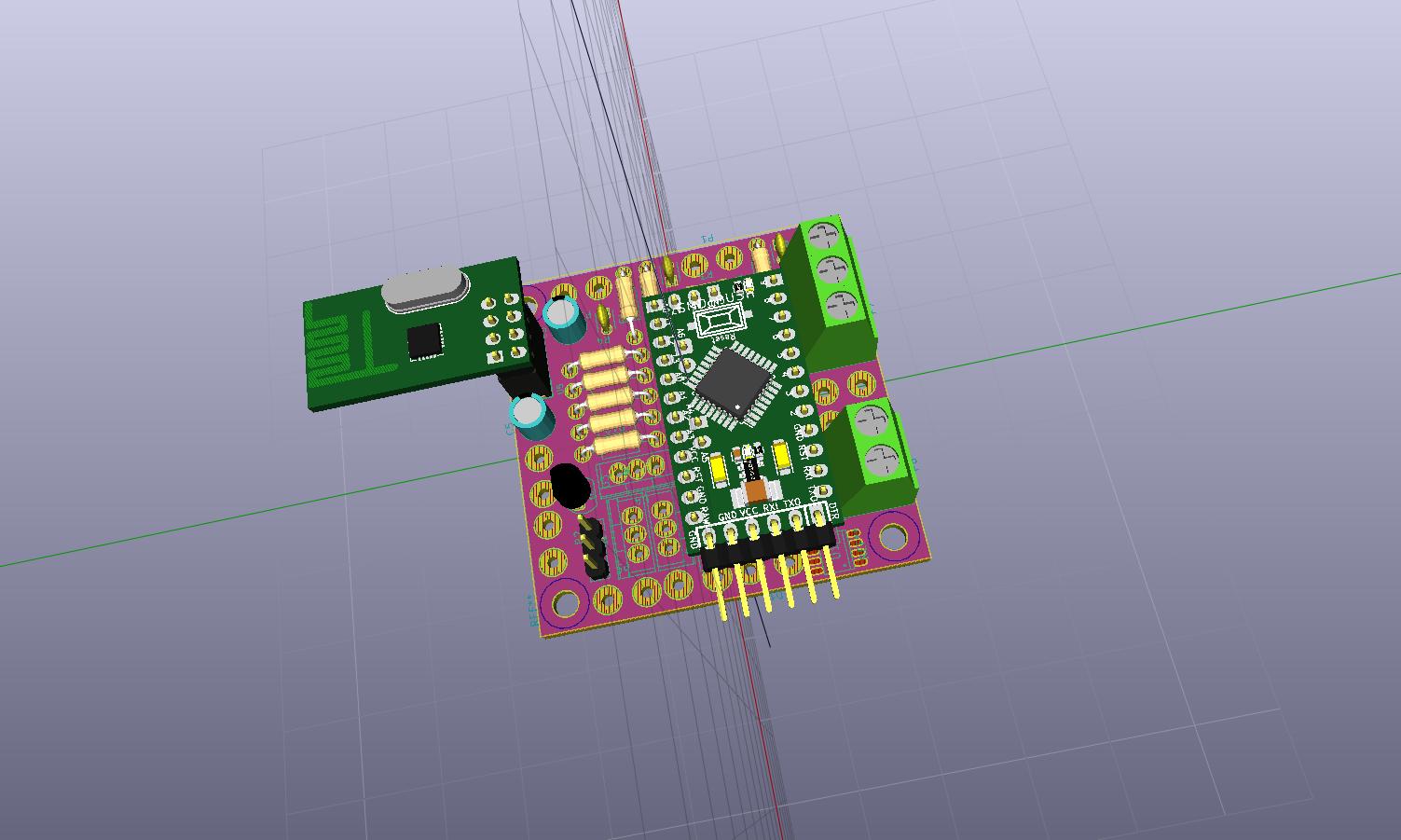
                      Initial placement is done and this is what it looks like....very crowded board. Had to place the comparator underneath the pro mini, is that going to be an issue?0_1466743436714_12vDist.jpg

                      1 Reply Last reply
                      0
                      • A Offline
                        A Offline
                        activemind
                        wrote on last edited by
                        #11

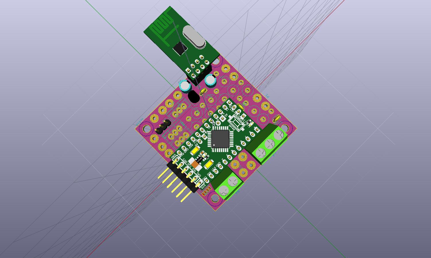
                        Also, thinking ahead about routing this board. Is it okay to do a GND pour on one side and 12V on the other?

                        -AM

                        1 Reply Last reply
                        0
                        • A Offline
                          A Offline
                          activemind
                          wrote on last edited by
                          #12

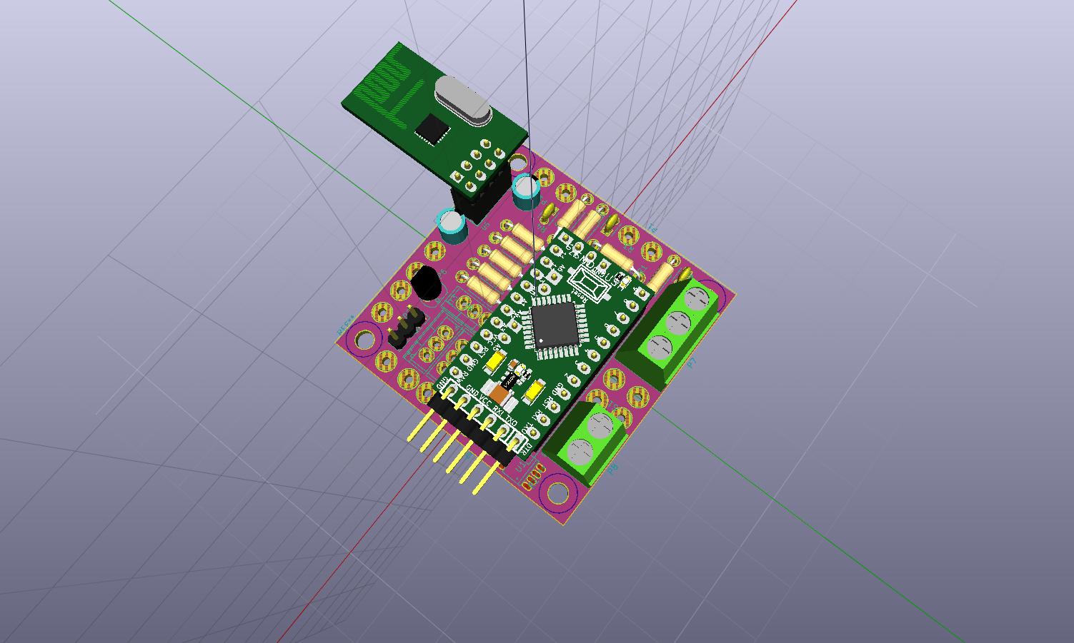
                          redid some of the placement and changed the resistors to horizontal mount from vertical.

                          looking better...I guess :-)

                          -AM

                          0_1466779995233_12vDist.jpg
                          0_1466780031719_12vDist1.jpg
                          0_1466780040696_12vDist2.jpg

                          1 Reply Last reply
                          0
                          • A Offline
                            A Offline
                            activemind
                            wrote on last edited by
                            #13

                            Debating about changing the size to 5x9 size so that it can fit inside a 5x10 box like this

                            -AM

                            1 Reply Last reply
                            0
                            • dbemowskD Offline
                              dbemowskD Offline
                              dbemowsk
                              wrote on last edited by
                              #14

                              A little off topic, but what PCB software are you using to do your illustrations and layout? It looks like nice software. Is it for windows only or is there a linux version?

                              Vera Plus running UI7 with MySensors, Sonoffs and 1-Wire devices
                              Visit my website for more Bits, Bytes and Ramblings from me: http://dan.bemowski.info/

                              A 1 Reply Last reply
                              0
                              • mfalkviddM Offline
                                mfalkviddM Offline
                                mfalkvidd
                                Mod
                                wrote on last edited by
                                #15

                                @activemind those boxes are 56x95mm on the inside (I have lots of them). They have mounting points in the corners, about 1.5mm from the inner wall. The outer diameter of the mounting points is 5.5mm and the inner diameter is approximately 2mm.

                                A 1 Reply Last reply
                                0
                                • dbemowskD dbemowsk

                                  A little off topic, but what PCB software are you using to do your illustrations and layout? It looks like nice software. Is it for windows only or is there a linux version?

                                  A Offline
                                  A Offline
                                  activemind
                                  wrote on last edited by
                                  #16

                                  @dbemowsk said:

                                  A little off topic, but what PCB software are you using to do your illustrations and layout? It looks like nice software. Is it for windows only or is there a linux version?

                                  I am a KiCad beginner. I started like a couple of days ago and this is my second PCB. Waiting for the first one to come back from fab house :-)

                                  -AM

                                  1 Reply Last reply
                                  0
                                  • mfalkviddM mfalkvidd

                                    @activemind those boxes are 56x95mm on the inside (I have lots of them). They have mounting points in the corners, about 1.5mm from the inner wall. The outer diameter of the mounting points is 5.5mm and the inner diameter is approximately 2mm.

                                    A Offline
                                    A Offline
                                    activemind
                                    wrote on last edited by
                                    #17

                                    @mfalkvidd said:

                                    @activemind those boxes are 56x95mm on the inside (I have lots of them). They have mounting points in the corners, about 1.5mm from the inner wall. The outer diameter of the mounting points is 5.5mm and the inner diameter is approximately 2mm.

                                    Thanks for the measurements @mfalkvidd . I am still debating about increasing the PCB size though because I looked at one of my existing boxes with the DC connector I am planning to use, and I realized that I need little more space because the connector extend out.

                                    Still playing with the placement on the PCB but looks like I have everything in place for now. Lets see what happens when I try to route it!

                                    The only thing I am concerned about is will placing the comparator IC underneath the pro mini cause any issues?

                                    -AM

                                    mfalkviddM 1 Reply Last reply
                                    0
                                    • A activemind

                                      @mfalkvidd said:

                                      @activemind those boxes are 56x95mm on the inside (I have lots of them). They have mounting points in the corners, about 1.5mm from the inner wall. The outer diameter of the mounting points is 5.5mm and the inner diameter is approximately 2mm.

                                      Thanks for the measurements @mfalkvidd . I am still debating about increasing the PCB size though because I looked at one of my existing boxes with the DC connector I am planning to use, and I realized that I need little more space because the connector extend out.

                                      Still playing with the placement on the PCB but looks like I have everything in place for now. Lets see what happens when I try to route it!

                                      The only thing I am concerned about is will placing the comparator IC underneath the pro mini cause any issues?

                                      -AM

                                      mfalkviddM Offline
                                      mfalkviddM Offline
                                      mfalkvidd
                                      Mod
                                      wrote on last edited by
                                      #18

                                      The only thing I am concerned about is will placing the comparator IC underneath the pro mini cause any issues?

                                      As long as the Pro Mini is placed high enouch to not touch the IC it won't cause any issues. The jmodule uses the same idea: https://www.openhardware.io/view/20/jModule

                                      1 Reply Last reply
                                      0
                                      • A Offline
                                        A Offline
                                        activemind
                                        wrote on last edited by
                                        #19

                                        Thanks @mfalkvidd for the link. I feel more confident that this might work.

                                        Didnt get a chance to work on this for past couple of days. Maybe soon...

                                        -AM

                                        1 Reply Last reply
                                        1
                                        • A Offline
                                          A Offline
                                          activemind
                                          wrote on last edited by
                                          #20

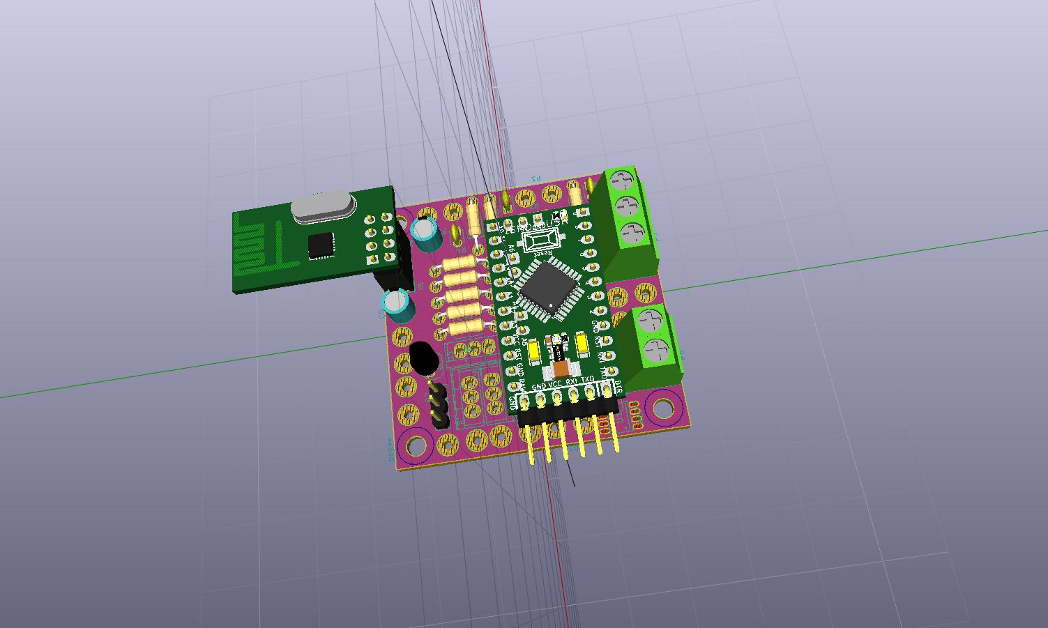
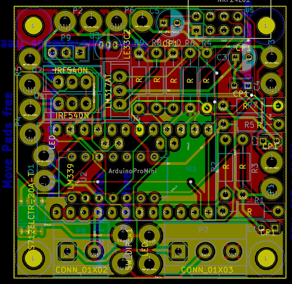
                                          Ok, so the board is routed. This was fun....very crowded board...at least by my noob standards :-)

                                          Done all DRC and connectivity checks...looks good.

                                          -AM

                                          0_1467210454056_12vDist-PCB.jpg

                                          1 Reply Last reply
                                          1
                                          Reply
                                          • Reply as topic
                                          Log in to reply
                                          • Oldest to Newest
                                          • Newest to Oldest
                                          • Most Votes


                                          27

                                          Online

                                          11.7k

                                          Users

                                          11.2k

                                          Topics

                                          113.1k

                                          Posts


                                          Copyright 2025 TBD   |   Forum Guidelines   |   Privacy Policy   |   Terms of Service
                                          • Login

                                          • Don't have an account? Register

                                          • Login or register to search.
                                          • First post
                                            Last post
                                          0
                                          • MySensors
                                          • OpenHardware.io
                                          • Categories
                                          • Recent
                                          • Tags
                                          • Popular