💬 vESPrino - The IOT Dongle
-
-
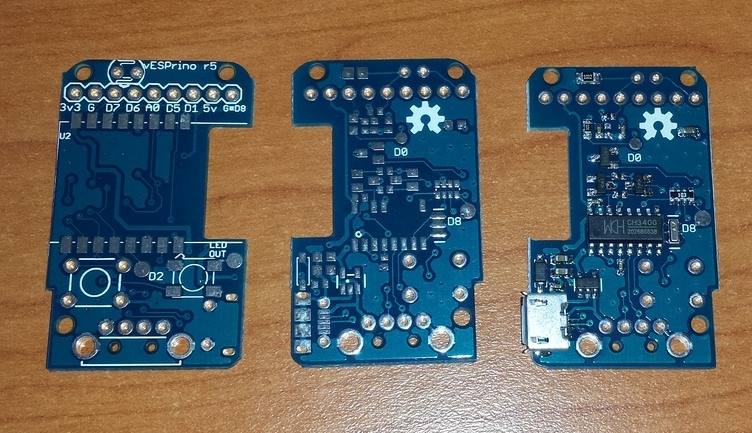
The final version of the boards contains few notable improvements
- Removed the PCB under the ESP8266 antenna. The previous design had PCB + Ground Plane, which resulted in VERY low reception. It worked just few meters away from the router.
- Removed the Temperature Probe - On the one hand - it does not really measure real temperature, on the other hand it populates the Single Analog port, and makes it unavailable for other usages
- Added place for an optional LDR (in case the Analog port is not used - one could add an LDR for added value)
- The connection between GPIO 16 and RST (Deep Sleep) is not bridged via a 0603 0ohm resistor (jumper). Depending on application it may be enabled or not
- Added a Power 5V line. That is - controlled via a SOT232 mosfet and one GPIO. This way you can connect power hungry modules and then turn them on or off. There are small mosfets rated ~ 2-3 amps for couple of cents.
- The big 12mhz crystal for the CH340G was replaced by a small patch ceramic oscillator to save space
- Added an additional mounting hole
- Added additional test pads for the unused GPIOs
- Added one Diode in series with the power to the WS2812B LED. It turned out, when powered directly via a USB Battery bank, the voltage can be 5.30-5.40v. And apparently WS2812B, does not light if VIN is > 5.15V. So putting a generic small Diode would drop 0.3-0.4V
Here is how the latest design looks like
Hello! It looks like you're interested in this conversation, but you don't have an account yet.
Getting fed up of having to scroll through the same posts each visit? When you register for an account, you'll always come back to exactly where you were before, and choose to be notified of new replies (either via email, or push notification). You'll also be able to save bookmarks and upvote posts to show your appreciation to other community members.
With your input, this post could be even better 💗
Register Login