[SOLVED] ESP8266 - RFM69W - Are they talking??
-
Hi,
I'm working on a project for an ESP8266 RFM69W Gateway and Sensor.
I currently have the gateway and sensor set up and about 1M away from each other.The gateway seems to start fine and gives the following output on serial monitor
Gateway
0;255;3;0;9;Starting gateway (RRNGE-, 2.0.0)
0;255;3;0;9;TSM:INIT
0;255;3;0;9;TSM:RADIO:OK
0;255;3;0;9;TSM:GW MODE
0;255;3;0;9;TSM:READY
scandone
f 0, ....scandone
state: 0 -> 2 (b0)
state: 2 -> 3 (0)
state: 3 -> 5 (10)
add 0
aid 5
cntconnected with SKYD7336, channel 11
dhcp client start...
.ip:192.168.0.10,mask:255.255.255.0,gw:192.168.0.1
.IP: 192.168.0.10
0;255;3;0;9;No registration required
0;255;3;0;9;Init complete, id=0, parent=0, distance=0, registration=1
pm open,type:2 0
0;255;3;0;9;TSP:SANCHK:OKHowever when i start up the motionsensor node it doesn't seem to connect
Starting sensor (RRNNE-, 2.0.0)
TSM:INIT
TSM:RADIO:OK
TSP:ASSIGNID:OK (ID=254)
TSM:FPAR
TSP:MSG:SEND 254-254-255-255 s=255,cTSM:FPAR
scandone
state: 0 -> 2 (b0)
TSP:MSG:SEND 254-254-255-255 s=255,c=3,t=7,pt=0,l=0,sg=0,ft=0,st=bc:
state: 2 -> 3 (0)
state: 3 -> 5 (10)
add 0
aid 7
cntconnected with SKYD7336, channel 11
dhcp client start...
ip:192.168.0.24,mask:255.255.255.0,gw:192.168.0.1
TSM:FPAR
TSP:MSG:SEND 254-254-255-255 s=255,c=3,t=7,pt=0,l=0,sg=0,ft=0,st=bc:
TSM:FPAR
TSP:MSG:SEND 254-254-255-255 s=255,c=3,t=7,pt=0,l=0,sg=0,ft=0,st=bc:
!TSM:FPAR:FAIL
!TSM:FAILURE
TSM:PDT
pm open,type:2 0
TSM:INIT
TSM:RADIO:OK
TSP:ASSIGNID:OK (ID=254)
TSM:FPAR
TSP:MSG:SEND 254-254-255-255 s=255,c=3,t=7,pt=0,l=0,sg=0,ft=0,st=bc:
TSM:FPAR
TSP:MSG:SEND 254-254-255-255 s=255,c=3,t=7,pt=0,l=0,sg=0,ft=0,st=bc:
TSM:FPAR
TSP:MSG:SEND 254-254-255-255 s=255,c=3,t=7,pt=0,l=0,sg=0,ft=0,st=bc:
TSM:FPAR
TSP:MSG:SEND 254-254-255-255 s=255,c=3,t=7,pt=0,l=0,sg=0,ft=0,st=bc:
!TSM:FPAR:FAIL
!TSM:FAILURE
TSM:PDTThe motion sensor output is especially confusing because the motion sensor in theory doesnt know my SSID, however it says its connected to my wifi router etc.
As I say I'm pretty new to this so any help would be appreciated??
finally, is there a reference to allow me to make sense of the output messages or do i have to hack into the code?
@Dinnoc There's a reference to the meaning if the debug somewhere on the forum. @tekka might now where it is.
As far as I read other threads on the forum, your node is continuously looking for a gateway which it can't find. What happens if you put them farther away of each other?
Or both radio's on the same frequency?
-
Hi,
I'm working on a project for an ESP8266 RFM69W Gateway and Sensor.
I currently have the gateway and sensor set up and about 1M away from each other.The gateway seems to start fine and gives the following output on serial monitor
Gateway
0;255;3;0;9;Starting gateway (RRNGE-, 2.0.0)
0;255;3;0;9;TSM:INIT
0;255;3;0;9;TSM:RADIO:OK
0;255;3;0;9;TSM:GW MODE
0;255;3;0;9;TSM:READY
scandone
f 0, ....scandone
state: 0 -> 2 (b0)
state: 2 -> 3 (0)
state: 3 -> 5 (10)
add 0
aid 5
cntconnected with SKYD7336, channel 11
dhcp client start...
.ip:192.168.0.10,mask:255.255.255.0,gw:192.168.0.1
.IP: 192.168.0.10
0;255;3;0;9;No registration required
0;255;3;0;9;Init complete, id=0, parent=0, distance=0, registration=1
pm open,type:2 0
0;255;3;0;9;TSP:SANCHK:OKHowever when i start up the motionsensor node it doesn't seem to connect
Starting sensor (RRNNE-, 2.0.0)
TSM:INIT
TSM:RADIO:OK
TSP:ASSIGNID:OK (ID=254)
TSM:FPAR
TSP:MSG:SEND 254-254-255-255 s=255,cTSM:FPAR
scandone
state: 0 -> 2 (b0)
TSP:MSG:SEND 254-254-255-255 s=255,c=3,t=7,pt=0,l=0,sg=0,ft=0,st=bc:
state: 2 -> 3 (0)
state: 3 -> 5 (10)
add 0
aid 7
cntconnected with SKYD7336, channel 11
dhcp client start...
ip:192.168.0.24,mask:255.255.255.0,gw:192.168.0.1
TSM:FPAR
TSP:MSG:SEND 254-254-255-255 s=255,c=3,t=7,pt=0,l=0,sg=0,ft=0,st=bc:
TSM:FPAR
TSP:MSG:SEND 254-254-255-255 s=255,c=3,t=7,pt=0,l=0,sg=0,ft=0,st=bc:
!TSM:FPAR:FAIL
!TSM:FAILURE
TSM:PDT
pm open,type:2 0
TSM:INIT
TSM:RADIO:OK
TSP:ASSIGNID:OK (ID=254)
TSM:FPAR
TSP:MSG:SEND 254-254-255-255 s=255,c=3,t=7,pt=0,l=0,sg=0,ft=0,st=bc:
TSM:FPAR
TSP:MSG:SEND 254-254-255-255 s=255,c=3,t=7,pt=0,l=0,sg=0,ft=0,st=bc:
TSM:FPAR
TSP:MSG:SEND 254-254-255-255 s=255,c=3,t=7,pt=0,l=0,sg=0,ft=0,st=bc:
TSM:FPAR
TSP:MSG:SEND 254-254-255-255 s=255,c=3,t=7,pt=0,l=0,sg=0,ft=0,st=bc:
!TSM:FPAR:FAIL
!TSM:FAILURE
TSM:PDTThe motion sensor output is especially confusing because the motion sensor in theory doesnt know my SSID, however it says its connected to my wifi router etc.
As I say I'm pretty new to this so any help would be appreciated??
finally, is there a reference to allow me to make sense of the output messages or do i have to hack into the code?
-
thanks tekka,
I am running on and eSP8266-12 and using an RFM69W.
A few questions/points
-Can you confirm the pin assignments for ESP8266 - are they configurable?
-for the RFM69W should i add #define MY_IS_RFM69HW in the myconfig file?
-i have added 4.7uf caps on bothpower supplies and dont seem to be getting any reboots or funny SANCHK messages. (ive use esp alot so am used to power fluctuation issues)Code is pretty close to examples with static setting of node id and parent node id
GATEWAY
*
 * Make sure to fill in your ssid and WiFi password below for ssid & pass.
 */

#include <EEPROM.h>
#include <SPI.h>

// Enable debug prints to serial monitor
#define MY_DEBUG

// Use a bit lower baudrate for serial prints on ESP8266 than default in MyConfig.h
#define MY_BAUD_RATE 9600

#define MY_PARENT_NODE_ID 0
#define MY_NODE_ID 100

// Enables and select radio type (if attached)
//#define MY_RADIO_NRF24
#define MY_RADIO_RFM69

#define MY_GATEWAY_ESP8266

#define MY_ESP8266_SSID "888888"
#define MY_ESP8266_PASSWORD "8888888"

// Enable UDP communication
//#define MY_USE_UDP

// Set the hostname for the WiFi Client. This is the hostname
// it will pass to the DHCP server if not static.
 #define MY_ESP8266_HOSTNAME "sensor-gateway"

// Enable MY_IP_ADDRESS here if you want a static ip address (no DHCP)
//#define MY_IP_ADDRESS 192,168,178,87

// If using static ip you need to define Gateway and Subnet address as well
//#define MY_IP_GATEWAY_ADDRESS 192,168,178,1
//#define MY_IP_SUBNET_ADDRESS 255,255,255,0

// The port to keep open on node server mode
#define MY_PORT 5003

// How many clients should be able to connect to this gateway (default 1)
#define MY_GATEWAY_MAX_CLIENTS 2

// Controller ip address. Enables client mode (default is "server" mode).
// Also enable this if MY_USE_UDP is used and you want sensor data sent somewhere.
//#define MY_CONTROLLER_IP_ADDRESS 192, 168, 178, 68

// Enable inclusion mode
#define MY_INCLUSION_MODE_FEATURE

// Enable Inclusion mode button on gateway
// #define MY_INCLUSION_BUTTON_FEATURE
// Set inclusion mode duration (in seconds)
#define MY_INCLUSION_MODE_DURATION 60
// Digital pin used for inclusion mode button
#define MY_INCLUSION_MODE_BUTTON_PIN  3


// Flash leds on rx/tx/err
 #define MY_LEDS_BLINKING_FEATURE
// Set blinking period
 #define MY_DEFAULT_LED_BLINK_PERIOD 300

// Led pins used if blinking feature is enabled above
#define MY_DEFAULT_ERR_LED_PIN 16  // Error led pin
#define MY_DEFAULT_RX_LED_PIN  16  // Receive led pin
#define MY_DEFAULT_TX_LED_PIN  16  // the PCB, on board LED

#if defined(MY_USE_UDP)
  #include <WiFiUDP.h>
#else
  #include <ESP8266WiFi.h>
#endif

#include <MySensors.h>

void setup() {
}

void presentation() {
  // Present locally attached sensors here
}


void loop() {
  // Send locally attached sensors data here
}
MOTION SENSOR
#define MY_BAUD_RATE 9600 // Enable debug prints #define MY_DEBUG // Enable and select radio type attached //#define MY_RADIO_NRF24 #define MY_RADIO_RFM69 #define MY_PARENT_NODE_ID 100 #define MY_NODE_ID 45 #include <SPI.h> #include <MySensors.h> unsigned long SLEEP_TIME = 120000; // Sleep time between reports (in milliseconds) #define DIGITAL_INPUT_SENSOR 3 // The digital input you attached your motion sensor. (Only 2 and 3 generates interrupt!) #define CHILD_ID 1 // Id of the sensor child // Initialize motion message MyMessage msg(CHILD_ID, V_TRIPPED); void setup() { pinMode(DIGITAL_INPUT_SENSOR, INPUT); // sets the motion sensor digital pin as input } void presentation() { // Send the sketch version information to the gateway and Controller sendSketchInfo("Motion Sensor", "1.0"); // Register all sensors to gw (they will be created as child devices) present(CHILD_ID, S_MOTION); } void loop() { // Read digital motion value boolean tripped = digitalRead(DIGITAL_INPUT_SENSOR) == HIGH; Serial.println("in Loop"); Serial.println(tripped); send(msg.set(tripped?"1":"0")); // Send tripped value to gw // Sleep until interrupt comes in on motion sensor. Send update every two minute. sleep(digitalPinToInterrupt(DIGITAL_INPUT_SENSOR), CHANGE, SLEEP_TIME); } -
thanks tekka,
I am running on and eSP8266-12 and using an RFM69W.
A few questions/points
-Can you confirm the pin assignments for ESP8266 - are they configurable?
-for the RFM69W should i add #define MY_IS_RFM69HW in the myconfig file?
-i have added 4.7uf caps on bothpower supplies and dont seem to be getting any reboots or funny SANCHK messages. (ive use esp alot so am used to power fluctuation issues)Code is pretty close to examples with static setting of node id and parent node id
GATEWAY
*
 * Make sure to fill in your ssid and WiFi password below for ssid & pass.
 */

#include <EEPROM.h>
#include <SPI.h>

// Enable debug prints to serial monitor
#define MY_DEBUG

// Use a bit lower baudrate for serial prints on ESP8266 than default in MyConfig.h
#define MY_BAUD_RATE 9600

#define MY_PARENT_NODE_ID 0
#define MY_NODE_ID 100

// Enables and select radio type (if attached)
//#define MY_RADIO_NRF24
#define MY_RADIO_RFM69

#define MY_GATEWAY_ESP8266

#define MY_ESP8266_SSID "888888"
#define MY_ESP8266_PASSWORD "8888888"

// Enable UDP communication
//#define MY_USE_UDP

// Set the hostname for the WiFi Client. This is the hostname
// it will pass to the DHCP server if not static.
 #define MY_ESP8266_HOSTNAME "sensor-gateway"

// Enable MY_IP_ADDRESS here if you want a static ip address (no DHCP)
//#define MY_IP_ADDRESS 192,168,178,87

// If using static ip you need to define Gateway and Subnet address as well
//#define MY_IP_GATEWAY_ADDRESS 192,168,178,1
//#define MY_IP_SUBNET_ADDRESS 255,255,255,0

// The port to keep open on node server mode
#define MY_PORT 5003

// How many clients should be able to connect to this gateway (default 1)
#define MY_GATEWAY_MAX_CLIENTS 2

// Controller ip address. Enables client mode (default is "server" mode).
// Also enable this if MY_USE_UDP is used and you want sensor data sent somewhere.
//#define MY_CONTROLLER_IP_ADDRESS 192, 168, 178, 68

// Enable inclusion mode
#define MY_INCLUSION_MODE_FEATURE

// Enable Inclusion mode button on gateway
// #define MY_INCLUSION_BUTTON_FEATURE
// Set inclusion mode duration (in seconds)
#define MY_INCLUSION_MODE_DURATION 60
// Digital pin used for inclusion mode button
#define MY_INCLUSION_MODE_BUTTON_PIN  3


// Flash leds on rx/tx/err
 #define MY_LEDS_BLINKING_FEATURE
// Set blinking period
 #define MY_DEFAULT_LED_BLINK_PERIOD 300

// Led pins used if blinking feature is enabled above
#define MY_DEFAULT_ERR_LED_PIN 16  // Error led pin
#define MY_DEFAULT_RX_LED_PIN  16  // Receive led pin
#define MY_DEFAULT_TX_LED_PIN  16  // the PCB, on board LED

#if defined(MY_USE_UDP)
  #include <WiFiUDP.h>
#else
  #include <ESP8266WiFi.h>
#endif

#include <MySensors.h>

void setup() {
}

void presentation() {
  // Present locally attached sensors here
}


void loop() {
  // Send locally attached sensors data here
}
MOTION SENSOR
#define MY_BAUD_RATE 9600 // Enable debug prints #define MY_DEBUG // Enable and select radio type attached //#define MY_RADIO_NRF24 #define MY_RADIO_RFM69 #define MY_PARENT_NODE_ID 100 #define MY_NODE_ID 45 #include <SPI.h> #include <MySensors.h> unsigned long SLEEP_TIME = 120000; // Sleep time between reports (in milliseconds) #define DIGITAL_INPUT_SENSOR 3 // The digital input you attached your motion sensor. (Only 2 and 3 generates interrupt!) #define CHILD_ID 1 // Id of the sensor child // Initialize motion message MyMessage msg(CHILD_ID, V_TRIPPED); void setup() { pinMode(DIGITAL_INPUT_SENSOR, INPUT); // sets the motion sensor digital pin as input } void presentation() { // Send the sketch version information to the gateway and Controller sendSketchInfo("Motion Sensor", "1.0"); // Register all sensors to gw (they will be created as child devices) present(CHILD_ID, S_MOTION); } void loop() { // Read digital motion value boolean tripped = digitalRead(DIGITAL_INPUT_SENSOR) == HIGH; Serial.println("in Loop"); Serial.println(tripped); send(msg.set(tripped?"1":"0")); // Send tripped value to gw // Sleep until interrupt comes in on motion sensor. Send update every two minute. sleep(digitalPinToInterrupt(DIGITAL_INPUT_SENSOR), CHANGE, SLEEP_TIME); }@Dinnoc said:
I am running on and eSP8266-12 and using an RFM69W.
A few questions/points
-Can you confirm the pin assignments for ESP8266 - are they configurable?The SPI bus signals (MISO + MOSI + SCK) seems to be hardwired to GPIO 12, 13 and 14
The interrupt pin and chip select are configurable - for my gateway I use#define MY_RF69_IRQ_PIN 15
#define MY_RF69_SPI_CS 16Remember that GPIO 16 doesn't support interrupts on the ESP8266 so it can't be used for interrupts. I avoid using GPIO 4+5 since these are default pins for I2C and I have several ideas on using I2C on the gateway (status display or locally attached sensors)
GPIO 0 + 2 are usable for LED's
-for the RFM69W should i add #define MY_IS_RFM69HW in the myconfig file?
No, W and CW have lower output and should not have MY_IS_RFM69HW defined - it's only for HW and HCW version
Also, did you configure MY_RFM69_FREQUENCY to match your frequency band?
-i have added 4.7uf caps on bothpower supplies and dont seem to be getting any reboots or funny SANCHK messages. (ive use esp alot so am used to power fluctuation issues)
I have seen a lot of issues with ESP8266 + RFM69 stability. Somehow it seems to help to touch the antenne of the RFM69! Several other people I have talked has seen this issue as well. I have solved it in two ways
- Connecting a dipole antenna or a quarterwave antenna on a ground plane, to the RFM69 instead of a quarterwave (piece of wire)
- Laying out a proper 2-layer PCB with a good groundplane
My current gateway is using a proper PCB and is very reliable
The RFM69 library from lowpowerlabs comes with two simple sketches (gateway and node) which are quite handy for verifying the RF setup. You need to comment out a few things to compile on the ESP8266, but it's pretty straight forward
- Jan
-
Thanks Chrille,
A few follow up questions
I have
MISO --> 12
MOSI --> 13
SCK --> 14
NSS (assume this is IRQ) --> 15 (which is also pulled down to earth with a resistor)I dont have anything going to 16 , which pin on the RF69 is chip select?
Frequency band is 868 and is configured correctly
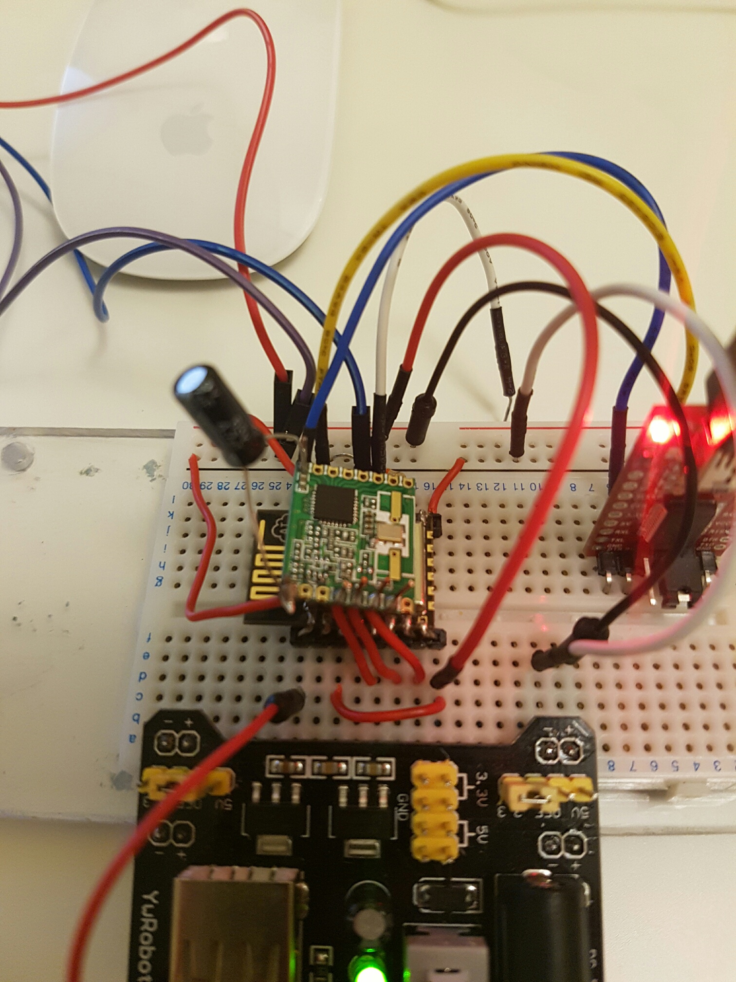
And finally i dont have an antenna. my devices are about 0.5m away from each other. Do i need an antenna? If so does it need to be a speicific length? and what socket of the RF69 do it attach it to (ANA??)
I attach an image of my set up, its not pretty, but it might help.
-
Thanks Chrille,
A few follow up questions
I have
MISO --> 12
MOSI --> 13
SCK --> 14
NSS (assume this is IRQ) --> 15 (which is also pulled down to earth with a resistor)I dont have anything going to 16 , which pin on the RF69 is chip select?
Frequency band is 868 and is configured correctly
And finally i dont have an antenna. my devices are about 0.5m away from each other. Do i need an antenna? If so does it need to be a speicific length? and what socket of the RF69 do it attach it to (ANA??)
I attach an image of my set up, its not pretty, but it might help.
@Dinnoc said:
I have
MISO --> 12
MOSI --> 13
SCK --> 14That's correct
NSS (assume this is IRQ) --> 15 (which is also pulled down to earth with a resistor)
No, NSS is chip select (MY_RF69_SPI_CS)
IRQ needs to go to DIO0 (MY_RF69_IRQ_PIN)(No need to configure MY_RF69_IRQ_NUM on ESP8266 was pin and IRQ number always is the same on ESP8266)
So you need 5 connections (MISO, MOSI, SCK, NSS and IRQ) to the ESP8266 + VCC/GND
And finally i dont have an antenna. my devices are about 0.5m away from each other. Do i need an antenna? If so does it need to be a speicific length? and what socket of the RF69 do it attach it to (ANA??)
A quarterwave at 868 MHz is approx 9 cm, so go with a piece of wire at that length, connected to ANA
It would probably work without an antenna, but to product the PA of the module you should connect just a simple antennnaLooking at your picture it looks very much like a HW module, and not a H module, so I suggest you configure isRFM69HW
- Jan
-
All working now, thanks Chrille!!
For anyone else trying to get RFM69W working with ESP8266
I have
MISO -> GPIO12
MOSI -> GPIO13
SCK -> GPIO14
NSS - > GPIO16
DIO0 ->GPIO15 (Which is also pulled down with a 10k resistor)
ANA -> antenna (to be honest i eyeballed 9cm but haven't measured it (was going to trim afterwards))
VCC -> 3.3V
GND -> GNDI also soldered a 4.7uf cap over the power and ground of the RFM69W directly on the RFM69W PCB
For the power supply i have a 5V USB supply (old phone charger) with a 1000uf cap over the +ve and -ve. then and LD1117 to feed 3.3V to the ESP and the RFM69. Should probably also have 47uf cap somewhere on the 3.3V side as well.
I saw people talking about them being too close as well. I tested most of mine about 50cm apart with no major issues.
I made the following mods to get either the gateway or node sketch working
#define MY_RF69_IRQ_PIN 15
#define MY_RF69_SPI_CS 16
All makes for a pretty cheap gateway. I was planning on using the ESP for nodes as well but is seems its power consumption is far greater than the arduino mini pro, so i ordered a few of them for nothing and will build my nodes based on those.
Hello! It looks like you're interested in this conversation, but you don't have an account yet.
Getting fed up of having to scroll through the same posts each visit? When you register for an account, you'll always come back to exactly where you were before, and choose to be notified of new replies (either via email, or push notification). You'll also be able to save bookmarks and upvote posts to show your appreciation to other community members.
With your input, this post could be even better 💗
Register Login