Can't get started
-
I am trying to get started with building the Mysensors Ethernet Gateway (Arduino Uno with W5100 shield). Whatever I try I do not get it to work due to zillions of compilation errors (files not found, etc.). Would it be possible to create a very simple step by step "build Ethernet gateway" including EXACT instructions which libraries to use and where to put them i.e. :
STEP 1 : Download this and that file and put them in : "C:\PROGRAM FILES\ARDUINO\LIBRARIES"
STEP 2: Download sketch this and that and put them in folder blablabla.
ETC.Obviously the current instruction video's don't work. It is not that I am completely new to programming but all the contradictions dazzle me a bit.
Thanks in advance!
As @mfalkvidd has said you are starting out with MySensors right in the changeover to V2 so there is understandably a lot of data still to be updated on the site.
luckily for you the w5100 gateway is even easier to do on V2, no more changing settings in the config files etc.
So the first thing you must do is remove the MySensors library you have installed as it does not appear to be in the right place and may conflict with the new install.
Make sure your IDE is the one from arduino.cc and not from arduino.org
You can then install the MySensors v2 library using the library manager with just a couple of mouse clicks. This will put everything in the right place. See instructions in this post.
When the MySensors library is installed it also includes many of the example sketches as well. The w5100 gateway is also included. So you just need to open it from the IDE example menu .
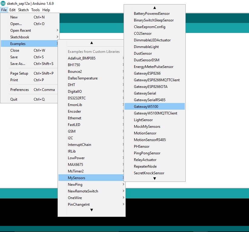
The sketch should work with your shield without much change needed. You will have to change the line that sets the ip address to the address you want.
#define MY_IP_ADDRESS 192,168,178,66 // If this is disabled, DHCP is used to retrieve addressThe wiring for the radio etc will be the same as in the V1.5 w5100 guide
Remember you no longer need to change any MySensors config files either. -
Hi Boots33,
Thanks a lot for all the explanation! It looks very clear. Tonight I will try again. I might have the wrong Arduino compiler.
Thanks again,Lars
-
As @mfalkvidd has said you are starting out with MySensors right in the changeover to V2 so there is understandably a lot of data still to be updated on the site.
luckily for you the w5100 gateway is even easier to do on V2, no more changing settings in the config files etc.
So the first thing you must do is remove the MySensors library you have installed as it does not appear to be in the right place and may conflict with the new install.
Make sure your IDE is the one from arduino.cc and not from arduino.org
You can then install the MySensors v2 library using the library manager with just a couple of mouse clicks. This will put everything in the right place. See instructions in this post.
When the MySensors library is installed it also includes many of the example sketches as well. The w5100 gateway is also included. So you just need to open it from the IDE example menu .
The sketch should work with your shield without much change needed. You will have to change the line that sets the ip address to the address you want.
#define MY_IP_ADDRESS 192,168,178,66 // If this is disabled, DHCP is used to retrieve addressThe wiring for the radio etc will be the same as in the V1.5 w5100 guide
Remember you no longer need to change any MySensors config files either.Hi @Boots33,
I deleted all my Arduino files including the ones in the user\documents\ directory (I hate it when files are automatically installed there), downloaded the Arduino compiler from Arduino.cc compiled and uploaded the W5100 sketch. Everything seems to be working fine now. Also Ping says it is OK. Thanks again for your simple and clear instructions.
The only thing I do not understand is why the Setup and Loop section are empty and I wonder how I can use the gateway itself with a simple sensor. If would like to first test it with my Homey before I start buying all kinds of sensors.
Regards,
Lars -
Hi @Boots33,
I deleted all my Arduino files including the ones in the user\documents\ directory (I hate it when files are automatically installed there), downloaded the Arduino compiler from Arduino.cc compiled and uploaded the W5100 sketch. Everything seems to be working fine now. Also Ping says it is OK. Thanks again for your simple and clear instructions.
The only thing I do not understand is why the Setup and Loop section are empty and I wonder how I can use the gateway itself with a simple sensor. If would like to first test it with my Homey before I start buying all kinds of sensors.
Regards,
Lars@LarsMachiels said:
I deleted all my Arduino files including the ones in the user\documents\ directory (I hate it when files are automatically installed there), downloaded the Arduino compiler from Arduino.cc compiled and uploaded the W5100 sketch. Everything seems to be working fine now. Also Ping says it is OK. Thanks again for your simple and clear instructions.
Great news your MySensors journey has begun !
The only thing I do not understand is why the Setup and Loop section are empty
That is the power of libraries. Once you have defined this as a gateway all the work is then handled by the MySensors library so it only needs us to set up a few parameters. You will use libraries for many of the sensors you build.
and I wonder how I can use the gateway itself with a simple sensor. If would like to first test it with my Homey before I start buying all kinds of sensors.
Yes under V2 sensors can be added to the gateway but i have not done this so am not sure of the correct way. You can try the modified sketch below and see if it works. I have commented the changes I have added. This just adds a dummy sensor to the gateway sketch. You will have to change to your ip as well.
I am sure someone will let us know how it is done if this is not correct and then we will both know . :)
/** * The MySensors Arduino library handles the wireless radio link and protocol * between your home built sensors/actuators and HA controller of choice. * The sensors forms a self healing radio network with optional repeaters. Each * repeater and gateway builds a routing tables in EEPROM which keeps track of the * network topology allowing messages to be routed to nodes. * * Created by Henrik Ekblad <henrik.ekblad@mysensors.org> * Copyright (C) 2013-2015 Sensnology AB * Full contributor list: https://github.com/mysensors/Arduino/graphs/contributors * * Documentation: http://www.mysensors.org * Support Forum: http://forum.mysensors.org * * This program is free software; you can redistribute it and/or * modify it under the terms of the GNU General Public License * version 2 as published by the Free Software Foundation. * ******************************* * * REVISION HISTORY * Version 1.0 - Henrik EKblad * Contribution by a-lurker and Anticimex, * Contribution by Norbert Truchsess <norbert.truchsess@t-online.de> * Contribution by Tomas Hozza <thozza@gmail.com> * * * DESCRIPTION * The EthernetGateway sends data received from sensors to the ethernet link. * The gateway also accepts input on ethernet interface, which is then sent out to the radio network. * * The GW code is designed for Arduino 328p / 16MHz. ATmega168 does not have enough memory to run this program. * * LED purposes: * - To use the feature, uncomment WITH_LEDS_BLINKING in MyConfig.h * - RX (green) - blink fast on radio message recieved. In inclusion mode will blink fast only on presentation recieved * - TX (yellow) - blink fast on radio message transmitted. In inclusion mode will blink slowly * - ERR (red) - fast blink on error during transmission error or recieve crc error * * See http://www.mysensors.org/build/ethernet_gateway for wiring instructions. * */ // Enable debug prints to serial monitor #define MY_DEBUG // Enable and select radio type attached #define MY_RADIO_NRF24 //#define MY_RADIO_RFM69 // Enable gateway ethernet module type #define MY_GATEWAY_W5100 // W5100 Ethernet module SPI enable (optional if using a shield/module that manages SPI_EN signal) //#define MY_W5100_SPI_EN 4 // Enable Soft SPI for NRF radio (note different radio wiring is required) // The W5100 ethernet module seems to have a hard time co-operate with // radio on the same spi bus. #if !defined(MY_W5100_SPI_EN) && !defined(ARDUINO_ARCH_SAMD) #define MY_SOFTSPI #define MY_SOFT_SPI_SCK_PIN 14 #define MY_SOFT_SPI_MISO_PIN 16 #define MY_SOFT_SPI_MOSI_PIN 15 #endif // When W5100 is connected we have to move CE/CSN pins for NRF radio #ifndef MY_RF24_CE_PIN #define MY_RF24_CE_PIN 5 #endif #ifndef MY_RF24_CS_PIN #define MY_RF24_CS_PIN 6 #endif // Enable to UDP //#define MY_USE_UDP #define MY_IP_ADDRESS 192,168,178,66 // If this is disabled, DHCP is used to retrieve address // Renewal period if using DHCP //#define MY_IP_RENEWAL_INTERVAL 60000 // The port to keep open on node server mode / or port to contact in client mode #define MY_PORT 5003 // Controller ip address. Enables client mode (default is "server" mode). // Also enable this if MY_USE_UDP is used and you want sensor data sent somewhere. //#define MY_CONTROLLER_IP_ADDRESS 192, 168, 178, 254 // The MAC address can be anything you want but should be unique on your network. // Newer boards have a MAC address printed on the underside of the PCB, which you can (optionally) use. // Note that most of the Ardunio examples use "DEAD BEEF FEED" for the MAC address. #define MY_MAC_ADDRESS 0xDE, 0xAD, 0xBE, 0xEF, 0xFE, 0xED // Flash leds on rx/tx/err #define MY_LEDS_BLINKING_FEATURE // Set blinking period #define MY_DEFAULT_LED_BLINK_PERIOD 300 // Enable inclusion mode #define MY_INCLUSION_MODE_FEATURE // Enable Inclusion mode button on gateway #define MY_INCLUSION_BUTTON_FEATURE // Set inclusion mode duration (in seconds) #define MY_INCLUSION_MODE_DURATION 60 // Digital pin used for inclusion mode button #define MY_INCLUSION_MODE_BUTTON_PIN 3 // Uncomment to override default HW configurations //#define MY_DEFAULT_ERR_LED_PIN 7 // Error led pin //#define MY_DEFAULT_RX_LED_PIN 8 // Receive led pin //#define MY_DEFAULT_TX_LED_PIN 9 // the PCB, on board LED #include <SPI.h> #if defined(MY_USE_UDP) #include <EthernetUdp.h> #endif #include <Ethernet.h> #include <MySensors.h> /*--------------ADDED BY BOOTS-------------------*/ #define CHILD_ID_LIGHT 0 unsigned long WAIT_TIME = 10000; // time between reads (in milliseconds) MyMessage msg(CHILD_ID_LIGHT, V_LIGHT_LEVEL); /*----------------------------------------------*/ void setup() { } /*--------------ADDED BY BOOTS-------------------*/ void presentation() { // Send the sketch version information to the gateway and Controller sendSketchInfo("gateway sensor", "1.0"); // Register all sensors to gateway (they will be created as child devices) present(CHILD_ID_LIGHT, S_LIGHT_LEVEL); } /*----------------------------------------------*/ void loop() { /*--------------ADDED BY BOOTS-------------------*/ for (int i=0; i<20; i++) { send(msg.set(i)); Serial.println(i); wait(WAIT_TIME); } /*----------------------------------------------*/ } -
Thanks for your sketch. I tried the sketch but unfortunately I could not connect the gateway to my Homey. So maybe it is not the sketch but something else. I ordered some Arduino stuff and will try again with separate sensor node.
-
It could be my sketch, like I said i am not sure of what changes need to be made with sensors on the gateway. @mfalkvidd do you know the correct way to do this?
-
It could be my sketch, like I said i am not sure of what changes need to be made with sensors on the gateway. @mfalkvidd do you know the correct way to do this?
-
It could be my sketch, like I said i am not sure of what changes need to be made with sensors on the gateway. @mfalkvidd do you know the correct way to do this?
Hi @Boots33 ,
Today I got my Arduino stuf in. I took a new Nano V3, uploaded a sensor sketch, connected the radio etc. but still no success. I activated the debugger and it turns out that the radio doesn't initialise (RADIO:FAIL or something like that). I checked all my connections several times but those were all OK. The radio was working fine on the gateway (Uno + W5100 shield) so I tried the sensor sketch on the UNO. Now the radio was OK. Also tried the gateway on my Mega but there I get the same radio problem. So it seems I need another UNO to make it hopefully work. Or maybe there is another way (Burn new bootloader maybe?).
All suggestions are welcome.
Greetings,
Lars -
Hi @Boots33 ,
Today I got my Arduino stuf in. I took a new Nano V3, uploaded a sensor sketch, connected the radio etc. but still no success. I activated the debugger and it turns out that the radio doesn't initialise (RADIO:FAIL or something like that). I checked all my connections several times but those were all OK. The radio was working fine on the gateway (Uno + W5100 shield) so I tried the sensor sketch on the UNO. Now the radio was OK. Also tried the gateway on my Mega but there I get the same radio problem. So it seems I need another UNO to make it hopefully work. Or maybe there is another way (Burn new bootloader maybe?).
All suggestions are welcome.
Greetings,
Lars@LarsMachiels Yes I think RADIO:FAIL is usually some sort of hardware problem like wiring etc. Maybe try using new wires in case one of them is faulty. The Mega uses different pins for spi I think 50,51,52 so you will need to define and use those pins for spi for the radio to work
-
@LarsMachiels Yes I think RADIO:FAIL is usually some sort of hardware problem like wiring etc. Maybe try using new wires in case one of them is faulty. The Mega uses different pins for spi I think 50,51,52 so you will need to define and use those pins for spi for the radio to work
Finally I got at least something to work after a lot of trying and fiddling with Murphy next to my side. I found out that RADIO:OK doesn't necessarily mean the radio is actually working. Unfortunately automatically assigning an ID to the node didn't work, but with #define CHILD_ID 1 it was OK. I can see the node / gateway sending and receiving each others messages. When I comment #define MY_CONTROLLER_IP_ADDRESS the gateway keeps on initialising. I assume I need to use my controllers IP there. Can anybody explain me what this constant is for?
Even though I have been programming for more than 20 years I find it hard to get everything up and running but I will not rest before it is working fine. Next step will be to connect the Gateway to my Homey. So far thanks for all the help.
-
Finally I got at least something to work after a lot of trying and fiddling with Murphy next to my side. I found out that RADIO:OK doesn't necessarily mean the radio is actually working. Unfortunately automatically assigning an ID to the node didn't work, but with #define CHILD_ID 1 it was OK. I can see the node / gateway sending and receiving each others messages. When I comment #define MY_CONTROLLER_IP_ADDRESS the gateway keeps on initialising. I assume I need to use my controllers IP there. Can anybody explain me what this constant is for?
Even though I have been programming for more than 20 years I find it hard to get everything up and running but I will not rest before it is working fine. Next step will be to connect the Gateway to my Homey. So far thanks for all the help.
@LarsMachiels I found this in GatewayESP8266MQTTClient.ino:
// MQTT broker ip address.
#define MY_CONTROLLER_IP_ADDRESS 192, 168, 178, 68
this is in MyConfig.h:
// If MY_CONTROLLER_IP_ADDRESS is left un-defined, gateway acts as server allowing incoming connections.
//#define MY_CONTROLLER_IP_ADDRESS 192, 168, 178, 254
this in GatewayESP8266.ino
// Also enable this if MY_USE_UDP is used and you want sensor data sent somewhere.
//#define MY_CONTROLLER_IP_ADDRESS 192, 168, 178, 68
From GatewayW5100MQTTClient.ino
// MQTT broker ip address or url. Define one or the other.
//#define MY_CONTROLLER_URL_ADDRESS "m20.cloudmqtt.com"
#define MY_CONTROLLER_IP_ADDRESS 192, 168, 178, 68
So it seems to be controlling where the gateway should be sending data. How it will be sending data depends on other parameters, it seems UDP and MQTT are supported at least.
The parameter is also mentioned on https://www.mysensors.org/download/sensor_api_20 but so far without details.
-
Thanks @mfalkvidd. The thing is that I have a Homey controller which unfortunately does not see any sensors even though I have the GW send the data to the IP address of the controller (could be Homey app as well). When I let the gateway act as a server it keeps on restarting. Maybe this is due to the W5100 shield. When I disconnect the ethernet cable it starts normally. I will try another w5100 to see if the restarting problem will be solved. My modem does supply an IP and the GW is pingable in client mode.
@LarsMachiels There was a problem with some versions of the arduino ide that caused the rebooting. You may have to revert to an older version, I am using 1.6.9 and I have compiled the gateway without issue but some have had to go back to 1.6.7 See this post for more details.