RFM69HW temp-humidity node
-
Soldering an atmega328 smt is easy:
https://www.youtube.com/watch?v=UeCZ9AMG3Vo
according to that guy, anyway. Maybe the longer pads makes it so? -
I took a shot at soldering the smaller board with the much tinier atmega328p, but for now I've concluded that hand soldering such a small chip is simply more work than it's worth. Perhaps with a reflow oven....
I'm still waiting for the interstitial board to arrive.
This has a lot of detail about soldering the atmega328 surface mount:
https://www.youtube.com/watch?v=-yc3zEe0RA0
So, though it's obviously doable, I still wouldn't say it's "easy." -
This has a lot of detail about soldering the atmega328 surface mount:
https://www.youtube.com/watch?v=-yc3zEe0RA0
So, though it's obviously doable, I still wouldn't say it's "easy."I finally had success using the Dave Jones tack and reflow method. The hardest part is just ensuring that the chip is properly aligned after the tack. From that point on, iit goes relatively easy.
-
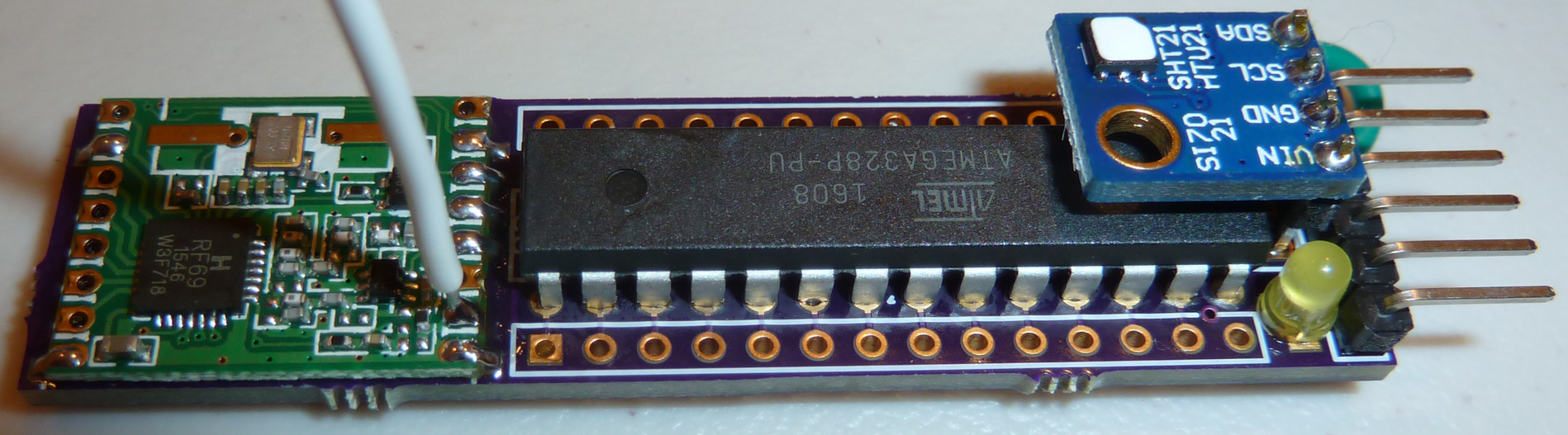
So, LED is blinking like it should, and I can download sketches to it. I plugged in an si7021 board, and that's working too:
Humidity: 44.42 Temperature: 22.22
Humidity: 44.40 Temperature: 22.22
Humidity: 44.43 Temperature: 22.23
Humidity: 44.42 Temperature: 22.22
Humidity: 44.43 Temperature: 22.21
Humidity: 44.43 Temperature: 22.22
Humidity: 44.44 Temperature: 22.22Looks as though a BME280 board, which has the same pinout as the si7021 board, should work also.

I tried the adafruit library on such a BME280, but it says it can't find the sensor. So, I tried the sparkfun library instead, and it is outputing false information:Temperature: 0.00 degrees C
Temperature: 32.00 degrees F
Pressure: 0.00 Pa
Altitude: 45846.20m
Altitude: 150414.04ft
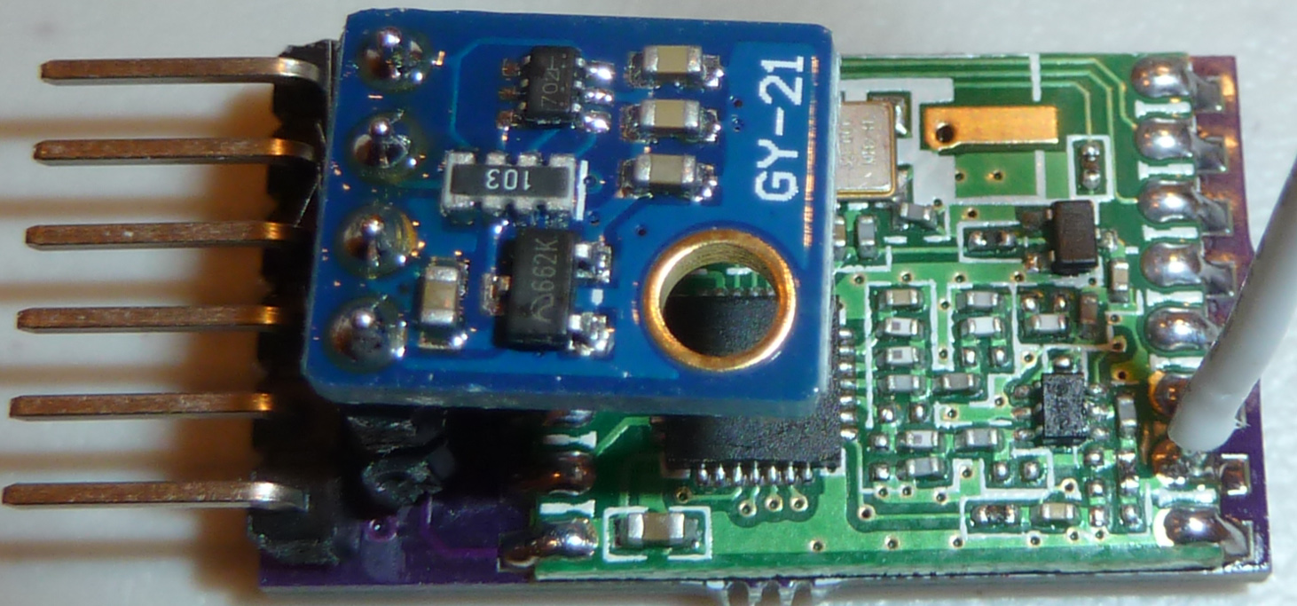
%RH: 0.00 %Looking at the back of the BME280 board , it looks like it may have a voltage regulator and/or level converter on it (?)..

Since I'm feeding it 3.3v, not 5v, then perhaps that's the problem.The part is 662K, and sure enough, it's a voltage regulator:
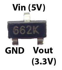
If I remove that and short Vin to the 3v3 lead, maybe it will work....
So, to see if it works at all, I hooked up the BME280 board to an arduino uno at 5v, and... still no joy. Apparently, I received a defective BME280. :disappointed: Murphy's Law strikes again. Therefore, I'll exchange it for another one. Meanwhile, I'll use the si7021.
-
Hello, I had a problem with BME280 too. Both Adafruit and Sparkfun use 0x77 as default address, but I have the same breakout board than you and the i2c address is 0x76.
Voltage regulator is not a problem it's a XC6206 and it's drawing close to nothing when you feed it with low voltage, and for battery voltage (3v down to 2V) the drop out voltage should be around 0.1V.You can pass the address of the sensor in the begin method, it defaults to the one defined in the h file which is 0x77
#define BME280_ADDRESS                (0x77)

 bool  begin(uint8_t addr = BME280_ADDRESS);
(I use the sparkfun library at the moment as it's easier to set the running mode of the sensor to switch it to sleep mode after measurement. Else it's using too much power for battery operation)
-
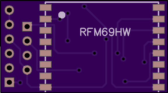
I also just now designed this pro mini interstitial board and sent it off to be fabbed:
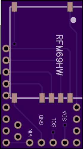
Just attach an RFM69HW and the si7021 to the board, and then plug it into a pro mini. Voila! You now have a temp-RH node. You will have to remove the LED from pin 13 on the pro mini, but that's no big deal. Also, it's obviously intended for a 3.3V pro mini, not a 5V pro mini.I suspect that for most people, this would be the simplest to put together. The board is less than 1 square inch in area.
@NeverDie
Nice. Could you please open your design? -> www.openhardware.io -
Hello, I had a problem with BME280 too. Both Adafruit and Sparkfun use 0x77 as default address, but I have the same breakout board than you and the i2c address is 0x76.
Voltage regulator is not a problem it's a XC6206 and it's drawing close to nothing when you feed it with low voltage, and for battery voltage (3v down to 2V) the drop out voltage should be around 0.1V.You can pass the address of the sensor in the begin method, it defaults to the one defined in the h file which is 0x77
#define BME280_ADDRESS                (0x77)

 bool  begin(uint8_t addr = BME280_ADDRESS);
(I use the sparkfun library at the moment as it's easier to set the running mode of the sensor to switch it to sleep mode after measurement. Else it's using too much power for battery operation)
@Nca78
Thank you! I changed the I2C address to 0x76, and now I get the correct readings (in this case, using Sparkfun library):Temperature: 22.77 degrees C
Temperature: 73.00 degrees F
Pressure: 99002.00 Pa
Altitude: 202.13m
Altitude: 663.15ft
%RH: 47.00 %Fantastic! It works after all. Thank you again.
-
@Nca78
Thank you! I changed the I2C address to 0x76, and now I get the correct readings (in this case, using Sparkfun library):Temperature: 22.77 degrees C
Temperature: 73.00 degrees F
Pressure: 99002.00 Pa
Altitude: 202.13m
Altitude: 663.15ft
%RH: 47.00 %Fantastic! It works after all. Thank you again.
I designed the miniature board in the earlier post for the temp-RH sensor to hover over the atmega328p.
Maybe it doesn't matter all that much, but after assembling one that way, I'm realizing it would be better to have it hover over the radio instead because the radio antenna means that the radio side is more likely to be facing up and the atmega328p is flat enough that it can be sat upon on the bottom with the radio on top without complaint. As it stands, the temp-RH sensor could still be installed on the radio side of the PCB, but it would be facing outward (resulting in a larger footprint) rather than inward, hovering over the radio. Since the point of this node is to be small, the status quo somewhat defeats the purpose. So, I'll likely be revising the PCB layout to make that change. Also, I'll be eliminating those RFM69 pads that don't actually need to be soldered, as that will reduce that soldering/assembly time. -
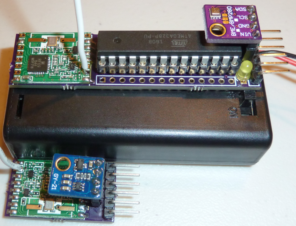
Here's the node from post #1 fully assembled, and with a BME280 instead of an si7021:
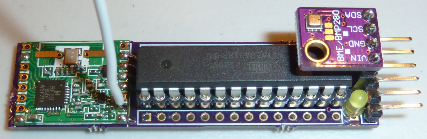
I'm starting to toy with the idea of having the radio also be a detachable module. The BME280 is the most expensive part on the board, and it's detachable. The atmega328p is detachable. If the radio were also detachable, it might speed up the assembly and test process. Also, if the radio were to go bad for some reason, one could just pop in a new one. Modularizing like that might make the whole thing easier to repair and troubleshoot, because you could always swap in "known good" modules to see if it fixes a particular problem. Anyhow, just an idea I'm kicking around. What do you all think? Make it more modular, or keep as is?
-
Here's the node from post #1 fully assembled, and with a BME280 instead of an si7021:
I'm starting to toy with the idea of having the radio also be a detachable module. The BME280 is the most expensive part on the board, and it's detachable. The atmega328p is detachable. If the radio were also detachable, it might speed up the assembly and test process. Also, if the radio were to go bad for some reason, one could just pop in a new one. Modularizing like that might make the whole thing easier to repair and troubleshoot, because you could always swap in "known good" modules to see if it fixes a particular problem. Anyhow, just an idea I'm kicking around. What do you all think? Make it more modular, or keep as is?
And making also the radio a detachable board would save you some board-space, thus reducing the cost again.
-
And making also the radio a detachable board would save you some board-space, thus reducing the cost again.
@GertSanders
Good point. I'd probably want to move the temp-rh sensor to the other side of the board as well so that it would be on the same side as the detachable radio.. In that case, it wouldn't need to sit so high, because it wouldn't need the clearance to get above the atmega328p. So, it would save on thickness that way. Overall thickness might be a wash, and it would be shorter too, so that sounds like a potential win. I think it's worth exploring.Not sure if there are 2mm pitch machine pins (?), but that might help save on thickness, and if so so that might be the best way to mount the RFM69.
I think I'll switch to an SMD LED after all and use the through-hole real estate occupied by the existing through-hole LED for dedicated wires soldered on to connect to batteries. Or perhaps I should consider some other kind of battery connector? It could be powered as is through dupont connectors on the ftdi header, but to me dupont connectors seem a bit loosey-goosey for a permanent battery connection--not sure how corrosion might affect a dupont connection over time.
-
Here's the assembled small Temp-RH node:
I suddenly realized that if I flipped the si7021 "upside down", then I could install it on the other size of the board from what I had originally intended, all while still using the existing pinout. -I'd prefer to have the actual sensor element facing up, but it works.So, as you can see, the entire thing is barely much bigger than the RFM69HW itself. On the opposite side is the SMD atmega328p-au , an SMD LED, an SMD resistor, and an SMD capacitor. That's it. I can reset the board and upload sketches to it using my FTDI adapter board, as I wrote about earlier in this thread.
-
Here's another board, but this time I simply soldered everything directly to the PCB:
As you would expect, it's a bit thinner than the version where modules plug-in, but not by so much that I think it would make any meaningful difference in most instances.FYI, this particular si7021 comes with a protective cover on it. You can get them either with or without the protective cover, but I think it makes more sense to get it with the cover because it helps mitigate against possible contaminants.
-
I just now tested out the RFM69HW radios, and they all appear to be functioning just fine. I even put one inside a closed refrigerator, since that is one of the applications, and I received a strong signal.
So, as far as I'm concerned, proof of concept is now completed for these two different board designs. It will be a good baseline to compare against as I make optimizations going forward.
-
This photo illustrates one of the original objectives, which was to have a node that's appropriately sized to be powered by two AA cells:
I think either one meets that goal. -
Nice work !
For the "big" board, as you're constrained by the size of the 2 AA, I would use a pro mini instead of the bare atmega (more flat), and put the sensor on the side of the radio. It would also leave a bit of space for extra sensor (light for example) and maybe atsha for signing ?For the small one I would make another board of similar size with a coin cell holder and a big (100-220µF) ceramic capacitor, and use pins to bring power to the "IC" board and do the spacing at the same time.
As it's a shame to have such a small board and such a huge power supply ;) -
This photo illustrates one of the original objectives, which was to have a node that's appropriately sized to be powered by two AA cells:
I think either one meets that goal.It seems the collection of small MySensor nodes is growing :-)
Nice work ! -
Nice work !
For the "big" board, as you're constrained by the size of the 2 AA, I would use a pro mini instead of the bare atmega (more flat), and put the sensor on the side of the radio. It would also leave a bit of space for extra sensor (light for example) and maybe atsha for signing ?For the small one I would make another board of similar size with a coin cell holder and a big (100-220µF) ceramic capacitor, and use pins to bring power to the "IC" board and do the spacing at the same time.
As it's a shame to have such a small board and such a huge power supply ;)@Nca78 said:
Nice work !
For the "big" board, as you're constrained by the size of the 2 AA, I would use a pro mini instead of the bare atmega (more flat), and put the sensor on the side of the radio. It would also leave a bit of space for extra sensor (light for example) and maybe atsha for signing ?For the small one I would make another board of similar size with a coin cell holder and a big (100-220µF) ceramic capacitor, and use pins to bring power to the "IC" board and do the spacing at the same time.
As it's a shame to have such a small board and such a huge power supply ;)Actually, they're really just proof-of-concept boards to confirm that the radio would work OK on such boards. Both nodes may have a fatal design flaw, which is that the sensor breakout boards may be running 24/7 even if the atmega328p is sleeping. Anyone know if the boards (not just the sensor chip) can be slept at <1uA current? If that's not possible, then I'll need to run them from a pin (or possibly some kind of load switch chip if their max current draw is ever greater than 20ma). I guess I'll need to measure it unless someone already has. Have you?
-
@Nca78 said:
Nice work !
For the "big" board, as you're constrained by the size of the 2 AA, I would use a pro mini instead of the bare atmega (more flat), and put the sensor on the side of the radio. It would also leave a bit of space for extra sensor (light for example) and maybe atsha for signing ?For the small one I would make another board of similar size with a coin cell holder and a big (100-220µF) ceramic capacitor, and use pins to bring power to the "IC" board and do the spacing at the same time.
As it's a shame to have such a small board and such a huge power supply ;)Actually, they're really just proof-of-concept boards to confirm that the radio would work OK on such boards. Both nodes may have a fatal design flaw, which is that the sensor breakout boards may be running 24/7 even if the atmega328p is sleeping. Anyone know if the boards (not just the sensor chip) can be slept at <1uA current? If that's not possible, then I'll need to run them from a pin (or possibly some kind of load switch chip if their max current draw is ever greater than 20ma). I guess I'll need to measure it unless someone already has. Have you?
@NeverDie I have measured a board based on pro mini with BME280 (put in sleep mode, that's why I use the Sparkfun library) and a BH1750 (also in sleep mode between measurements) and my meter was giving me 17-18µA which is beginning to be too much for a CR battery. But still after running 3 weeks on a chinese CR2032 I see no drop in voltage. BME280 is not so good IMHO for very low power as it's a bit long to make the measurements, and drawing up to a few hundreds of µA while doing so.
I'm also running a board based on pro mini with a SHT21 breakout board (same than yours, with the film as without it will get dirty and lose accuracy quickly). Pro mini + radio alone consume a few µA only (sleep mode of MySensors library) and extra consumption from SHT21 (connected to Vcc) is invisible. I tried to measure with my multimeter the consumption of the SHT21 breakout board alone and it just can't measure anything. Even during measurement my multimeter sees nothing as it's extremely quick.
I did a sketch without sleeps between consecutive sendings (very bad for coin cell), sending every minute (and even if temp/hum don't change it's sending battery voltage), flashing a led after each sending. And with power from 2 cheap chinese LR41 (capacity 25mAh) it's on the way to last 2 months... -
@NeverDie I have measured a board based on pro mini with BME280 (put in sleep mode, that's why I use the Sparkfun library) and a BH1750 (also in sleep mode between measurements) and my meter was giving me 17-18µA which is beginning to be too much for a CR battery. But still after running 3 weeks on a chinese CR2032 I see no drop in voltage. BME280 is not so good IMHO for very low power as it's a bit long to make the measurements, and drawing up to a few hundreds of µA while doing so.
I'm also running a board based on pro mini with a SHT21 breakout board (same than yours, with the film as without it will get dirty and lose accuracy quickly). Pro mini + radio alone consume a few µA only (sleep mode of MySensors library) and extra consumption from SHT21 (connected to Vcc) is invisible. I tried to measure with my multimeter the consumption of the SHT21 breakout board alone and it just can't measure anything. Even during measurement my multimeter sees nothing as it's extremely quick.
I did a sketch without sleeps between consecutive sendings (very bad for coin cell), sending every minute (and even if temp/hum don't change it's sending battery voltage), flashing a led after each sending. And with power from 2 cheap chinese LR41 (capacity 25mAh) it's on the way to last 2 months...@Nca78
I just now measured the si7021 and BME280 breakout boards using the Dave Jones Microcurrent device. I did nothing more than power them from a battery pack (2x AA Alkaline batteries) using Vin and GND, but the si7021 measured 8.4uA, and the BME280uA measured 8.1uA. Not bad at all, assuming that represents quiescent current.I suspect the easiest thing will be to power them from a pin on the atmega328p. That way they can be switched off when not in use. When time permits I'll do that and measure the current with a scope trace just to make sure any inrush current doesn't exceed 20ma (which is the max current an atmega328p pin is rated for).
When both the atmega328p and RFM69HW are sleeping just by themselves, the current draw can be as low as 250na (yes, nanoamps) with the right configuration.
Hello! It looks like you're interested in this conversation, but you don't have an account yet.
Getting fed up of having to scroll through the same posts each visit? When you register for an account, you'll always come back to exactly where you were before, and choose to be notified of new replies (either via email, or push notification). You'll also be able to save bookmarks and upvote posts to show your appreciation to other community members.
With your input, this post could be even better 💗
Register Login