How To - Doorbell Automation Hack
-
Hi guys,
I'm nearly there, but need a little help if anyone can!
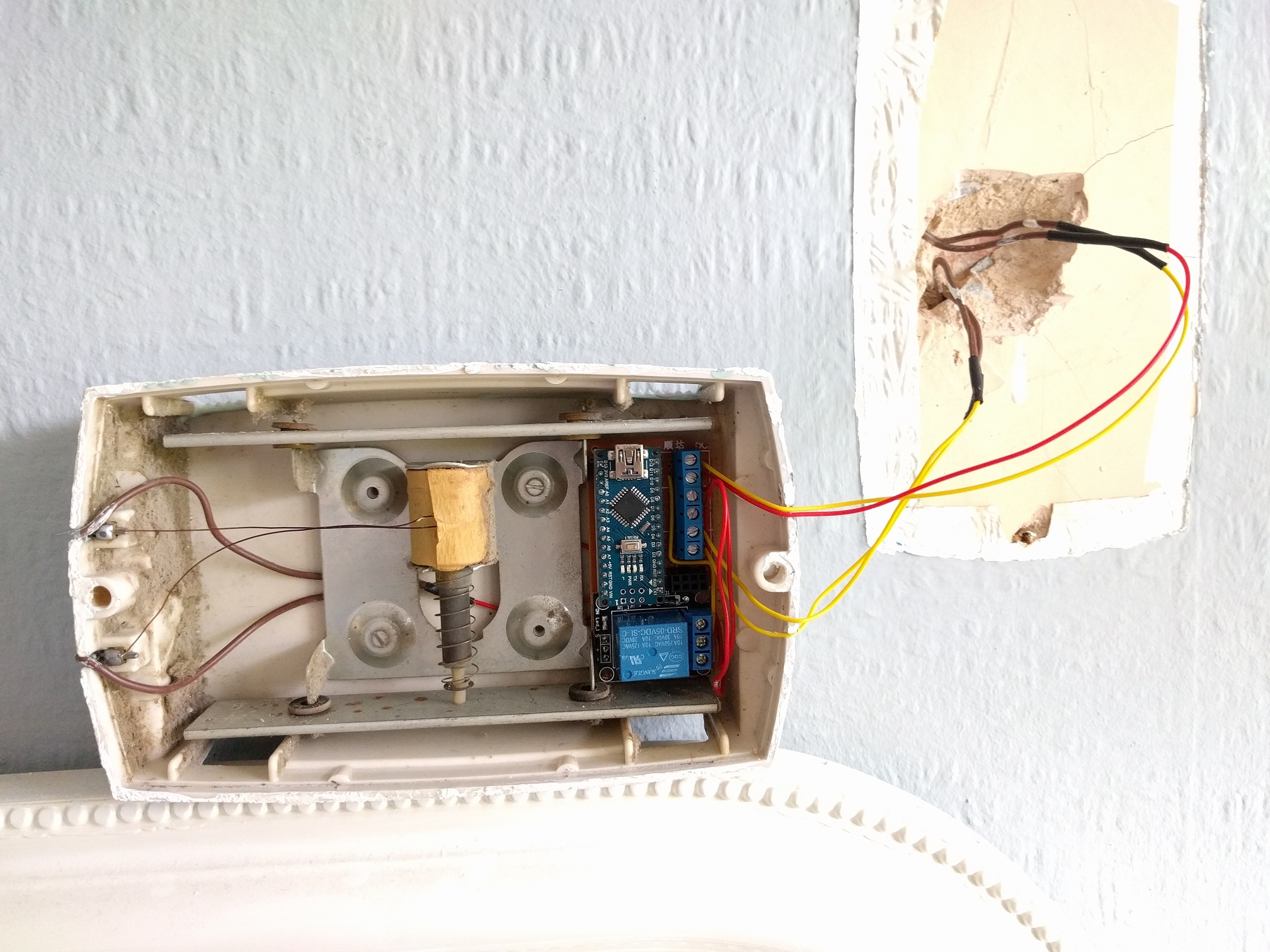
For my setup I've got a diode bridge followed immediately by a buck converter, so the doorbell's 18v AC comes down to 8v DC. My plan was to run the doorbell AND the arduino off this same supply, but I'm guessing now that it may not be possible. The reason for this was down to there only being 2 wires to the doorbell. The doorbell works fine off 8v DC and so does the arduino. The issue however is when i both power the arduino and the doorbell at the same time of the same supply. The relay opens and then the arduino resets. No chime.
What should I do? Wiring layout is exactly the same as above but the 8v DC loops through the relay to the doorbell as well as going to VIN/GND on the Arduino Nano.
I can't have the arduino at the power supply end as I need the doorbell button connections, so I'm hoping someone might have some ideas around splitting out the power supplies at the doorbell end? Or smoothing it or something like that.
Power is red/yellow from the wall. Doorbell button is yellow/yellow from the wall. brown/brown is soldered/heat shrunk to red/red within the housing. NRF is on headers, so it's lifted out in this photo.
Thanks,
Patrick
@pjblink - what are the components you have built in there? I see the Arduino Nano and a relay - are they all attached to a board? Is there a radio in there, too? I clicked on the (old) link above for Mini RBoard, but I get a gateway error when going to the page to purchase...
-
Hi crodgers,
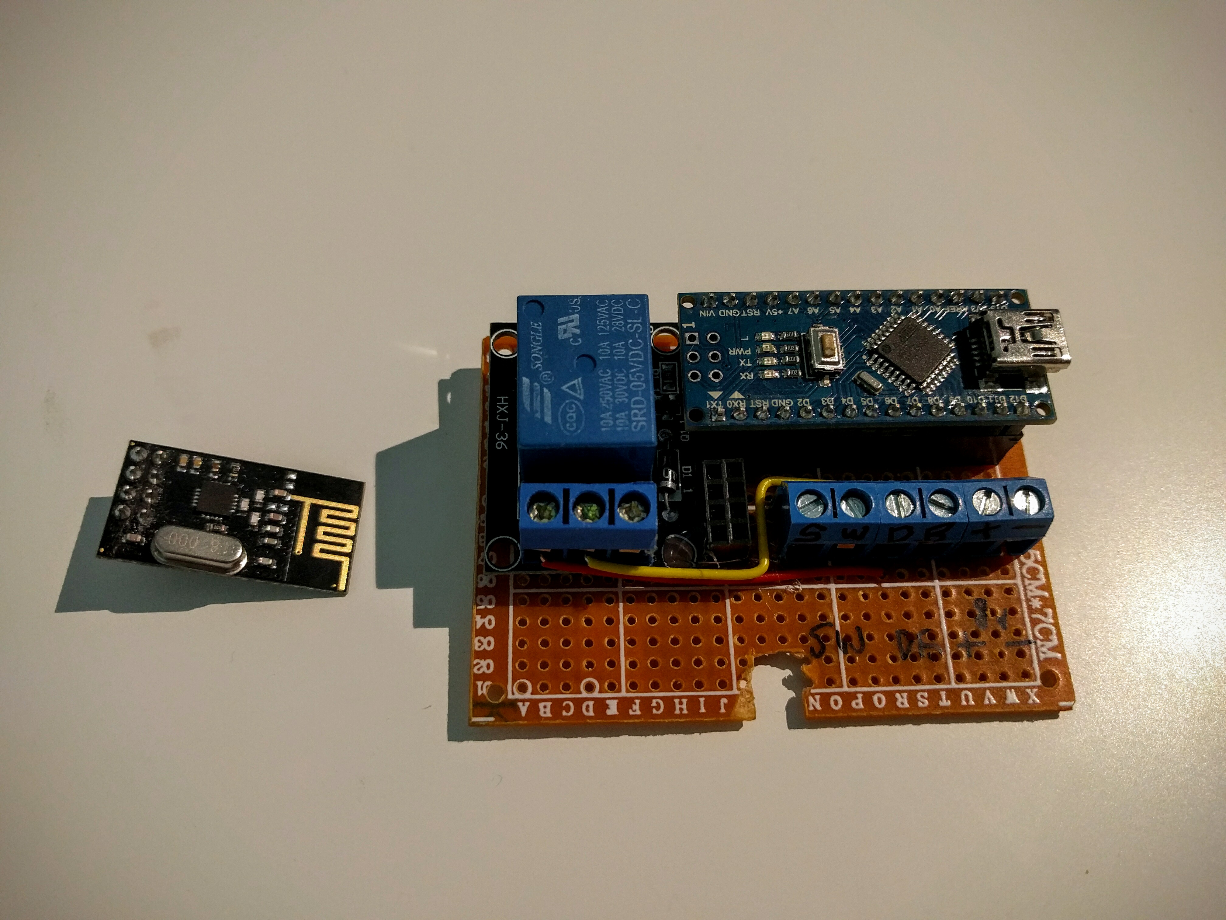
So yeh, there's a nano on headers, relay, nrf on headers and 3 wire terminals - 1 for the doorbell button, 1 for the bell itself and another for the DC IN. Everything is soldered to a prototyping board which has now been trimmed down to fit in the doorbell housing.
Thanks,
Patrick
-
Working without the doorbell load attached:
mysensors enabled doorbell working without loadFailing when I attach the load:
mysensors enabled doorbell failing with load -
I've just tried it with both 1000uF and then a 4700uF cap across VIN/GND on the arduino with only slightly better results. It'll ring, but the relay stays open most of the time and the arduino needs resetting to release it :(
@pjblink - late into the discussion, but have you tried changing to another power supply or another regulator? It might that its to unstable for your node... atleast temporary to rule things out.
Controller: Proxmox VM - Home Assistant
MySensors GW: Arduino Uno - W5100 Ethernet, Gw Shield Nrf24l01+ 2,4Ghz
MySensors GW: Arduino Uno - Gw Shield RFM69, 433mhz
RFLink GW - Arduino Mega + RFLink Shield, 433mhz -
@pjblink - late into the discussion, but have you tried changing to another power supply or another regulator? It might that its to unstable for your node... atleast temporary to rule things out.
@sundberg84 That was definitely on the cards...but it looks like I might have got it working. I did 4 things in one go, which is unlike me, so now I have to break things down to see which one helped (if it wasn't all)...1st thing was a 4700uF cap over the arduino VIN/GND, 2nd was a 1000uF cap over the relay +- 5v,… 3rd was to reflow a few of the GND solders and finally I dropped the voltage regulator from 8v to just under 7v...and hey presto...
-
@sundberg84 That was definitely on the cards...but it looks like I might have got it working. I did 4 things in one go, which is unlike me, so now I have to break things down to see which one helped (if it wasn't all)...1st thing was a 4700uF cap over the arduino VIN/GND, 2nd was a 1000uF cap over the relay +- 5v,… 3rd was to reflow a few of the GND solders and finally I dropped the voltage regulator from 8v to just under 7v...and hey presto...
@pjblink - a bad ground connection has been a pain for me alot of times... good you got it working.
-
So it kept failing after 2 or 3 rings...frustrating! I enabled all the debug and noticed it kept failing just before sending out the "off" message. It didn't reset, just stalled. This was the case even when powered by USB. And then I remembered how sensitive the NRFs are to fluctuations in power and I hadn't got round to putting a cap on there yet!!! I put a spare 1000uF (47uF are on order) and so far it hasnt caused me any further issues! So now I've got 3 huge capacitors on there, and it looks ok...touch wood.
-
Great how-to for a beginner. But now I'm stuck because of my lack of knowledge to rebuild the sketch for MySensors 2.0. Does anyone already rebuild it and willing to share?
-
How are you powering the relay? Are you trying to run it directly from an arduino data line? If so, that could be your problem. I am currently working on a motion sensor light with a PIR, LDR, and a relay. Now the relay I am using is a 12 volt relay, but the concept would be the same for a 5 volt relay. The idea is to use a transistor to trigger the relay from a separate power source. I used an 2N3904 NPN transistor to switch the the negative side of the power to the relay. You simply connect the emitter to your ground, the collector to the negative side of your relay and the base goes to your arduino data pin. You may need to add a pull-down resistor on the transistor base to ground depending on your situation. In my case it worked fine without it. Also, you should still of course put your flyback diode across your relay coil to prevent voltage spikes.
The above assumes that you are using a relay on it's own and not a relay module like the ones you find on ebay. The relay modules already have the transistor and diode already built in, and some even use an optocoupler for added isolation.
-
My test situation is Nano+Radio with double relay module and push button for the bell. Relay is powered by the 5V by Arduino, and i have tested this with the example sketch (+modification for double relay) and everything was working fine. The issue i am having is the original sketch (1 bell + 1 relay) is made for mysensors 1.x, and i am running 2.x and have no idea how te rewrite this.
@Samster here's the link to converting code to 2.0:
https://forum.mysensors.org/topic/4276/converting-a-sketch-from-1-5-x-to-2-0-xI followed this recently (different sketch) and it works just fine as long as you take your time and make sure you do each step properly. Post back on how you get on, if you're still stuck I might be able to give a hand next week but I'm pretty new at this myself.
-
@Samster here's the link to converting code to 2.0:
https://forum.mysensors.org/topic/4276/converting-a-sketch-from-1-5-x-to-2-0-xI followed this recently (different sketch) and it works just fine as long as you take your time and make sure you do each step properly. Post back on how you get on, if you're still stuck I might be able to give a hand next week but I'm pretty new at this myself.
@mrwomble Thank you, that's very helpfull, i will start puzzling around and share the result.
-
Ok, finally worked this again today. Here's the status. I modified the sketch to update it to 2.0, giving me this:
/*
 * The MySensors Arduino library handles the wireless radio link and protocol
 * between your home built sensors/actuators and HA controller of choice.
 * The sensors forms a self healing radio network with optional repeaters. Each
 * repeater and gateway builds a routing tables in EEPROM which keeps track of the
 * network topology allowing messages to be routed to nodes.
 *
 * Created by Henrik Ekblad <henrik.ekblad@mysensors.org>
 * Copyright (C) 2013-2015 Sensnology AB
 * Full contributor list: https://github.com/mysensors/Arduino/graphs/contributors
 *
 * Documentation: http://www.mysensors.org
 * Support Forum: http://forum.mysensors.org
 *
 * This program is free software; you can redistribute it and/or
 * modify it under the terms of the GNU General Public License
 * version 2 as published by the Free Software Foundation.
 *
 *******************************
 *
 * REVISION HISTORY
 * Version 1.0 - PeteWill
 * Version 2.0 - timropp, updating for MySensors 2.0
 *
 * DESCRIPTION
 * This sketch is used to control a doorbell ring with a relay as well as send an
 * alert when the buttons is pressed.  Connect the button to ground and digital
 * pin 3.  The relay controlling the doorbell is conntected to pin 4.
 *
 * Watch the How To video here: https://youtu.be/nMIcalwpstc
 */

#define MY_RADIO_NRF24
#define MY_REPEATER_FEATURE

#include <MySensors.h>
#include <SPI.h>
#include <Bounce2.h>

#define NODE_ID AUTO // or set to AUTO if you want gw to assign a NODE_ID for you.

#define DOORBELL_PIN A0      // Arduino Digital I/O pin number for the doorbell button
#define RELAY_PIN  4         // Arduino Digital I/O pin number for the relay
#define DOORBELL_CHILD_ID 0  //ID of the doorbell
#define SWITCH_CHILD_ID 1    // Id of the switch that will control doorbell sound
#define RELAY_ON 1
#define RELAY_OFF 0

Bounce debouncer = Bounce();

MyMessage switchMsg(SWITCH_CHILD_ID, V_LIGHT);
MyMessage doorbellMsg(DOORBELL_CHILD_ID, V_TRIPPED);

unsigned int doorbellDelay = 1000; // interval at which to keep the doorbell button sensor triggered (milliseconds). This is used to stop people (kids) from pressing it too often
unsigned int ringTime = 400; //How long the doorbell relay is on (in milliseconds)
unsigned long doorbellMillis;  //Used to keep track of the last doorbell button press
unsigned long doorbellTimer;  //Used to keep track of doorbell ring time
byte doorbellPreviousVal;  //Used to keep track of doorbell button pressed state
boolean ringDoorbell;  //Used to initiate the ring doorbell if statement
boolean doorbellSound; //Used to keep track if the doorbell should sound or be silent.  Value recieved from doorbell on/off switch
boolean doorbellOff = true;  //Used to keep track of doorbell ring state

void setup()
{
  // Setup the button and activate internal pull-up
  pinMode(DOORBELL_PIN, INPUT_PULLUP);

  // After setting up the button, setup debouncer
  debouncer.attach(DOORBELL_PIN);
  debouncer.interval(5);

  // Make sure relays are off when starting up
  digitalWrite(RELAY_PIN, RELAY_OFF);
  // Then set relay pins in output mode
  pinMode(RELAY_PIN, OUTPUT);

  // Set doorbellSound to last known state (using eeprom storage)
  doorbellSound = loadState(SWITCH_CHILD_ID);
}

void loop()
{
    unsigned long currentMillis = millis();
  //Check to see if doorbell button was pushed.
  if (currentMillis - doorbellMillis > doorbellDelay) //used to stop doorbell from being pressed too frequently
  {
    debouncer.update();
    // Read doorbell button value
    byte doorbellDetect = !debouncer.read();//read, then reverse the value so it will send correct trigger state to controller

    if (doorbellDetect != doorbellPreviousVal)
    {
      //Serial.print("doorbellDetect Value: ");
      //Serial.println(doorbellDetect);
      send(doorbellMsg.set(doorbellDetect));
      if (doorbellDetect == 1)
      {
        ringDoorbell = true;
        doorbellTimer = currentMillis;
      }
      doorbellMillis = currentMillis;
      doorbellPreviousVal = doorbellDetect;
    }
  }

  if (ringDoorbell)
  {
    if (doorbellSound)
    {
      if (doorbellOff)
      {
        digitalWrite(RELAY_PIN, RELAY_ON);
        //Serial.println("Doorbell sounded.");
        doorbellOff = false;
      }
      else
      {
        if (currentMillis - doorbellTimer > ringTime)
        {
          ringDoorbell = false;
          digitalWrite(RELAY_PIN, RELAY_OFF);
          //Serial.println("Doorbell off.");
          doorbellOff = true;
        }
      }
    }
  }
}

  void receive(const MyMessage &message) {
    // We only expect one type of message from controller. But we better check anyway.
    if (message.isAck()) {
      Serial.println("This is an ack from gateway");
    }

    if (message.type == V_LIGHT) {
      // Change relay state
      doorbellSound = message.getBool();
      // Store state in eeprom
      saveState(SWITCH_CHILD_ID, doorbellSound);

      // Write some debug info
      Serial.print("Incoming change for sensor:");
      Serial.print(message.sensor);
      Serial.print(", New status: ");
      Serial.println(message.getBool());
    }
  }

void presentation()
  {
  // Send the sketch version information to the gateway and Controller
  sendSketchInfo("Doorbell Monitor", "1.0");
    // Register all sensors to gw (they will be created as child devices)
  present(SWITCH_CHILD_ID, S_LIGHT);
  present(DOORBELL_CHILD_ID, S_MOTION);
  }
Sitting on my desk, it works fine. It appears in Home Assistant, clicks the relay when A0 is shorted to ground, and that appears in HASS as a motion event. Seems good, so I installed it in the doorbell. Doesn't work there. I get one ring when I hook up power, and then nothing. I checked again the leads from the physical doorbell button with a multimeter - I get a good continuity buzz when I press the button and silence when not pressed. Then I discovered something - if I physically unhook the wire going to A0 and reconnect it, the doorbell rings and I get that notification in Hass. If I unhook and reconnect the wire again, same thing. So that makes it appear that the A0 is being constantly grounded - is that possible? It acts like my physical doorbell button is stuck in the pressed position, but the multimeter indicates it's fine.
Further testing - If I connect the board to the doorbell system but leave the physical doorbell button disconnected, then attach a spare piece of wire to A0 and ground it, the system works perfectly. So it's definitely something related to the physical button.
On thing I've realized - I THINK the outdoor button is an illuminated one, which isn't illuminated with this system. Could that light be the cause? If so, why doesn't the continuity test show it as continuous? I think I'll go buy a basic non-illuminated button and install it and see if that works. Or just pull the button out of the wall, disconnect the wires, and then short them together. Duh, that'd be easier and cheaper. I'll try that this afternoon - have a wedding to get to first.
@timropp said:
I THINK the outdoor button is an illuminated one, which isn't illuminated with this system. Could that light be the cause?
The button is probably illuminated with LEDs and a resistor (depending how old it is). This could complete the circuit to the digital input on the arduino making it look like the button is pressed. It is probably not seen on a continuity test when the button is not pressed because the resistance is enough where you don't have full continuity. See if reversing the wires into the arduino A0 and ground gets it working. If the doorbell is illuminated with an LED and a resistor that should reverse the current flow of the LED/resistor into A0 on the arduino in effect preventing that problem.
-
It's definitely the illuminated button. I pulled it out and connecting the wires rings the bell correctly. I hadn't thought about swapping the wires... It is pretty new but I wasn't considering the possibility of it being led. I'll give that a try. Worst case, replace it with a non lit button. Just glad to have finally figured it out!
edit: actually, I'm betting it's not a LED. These buttons are typically on a 16VAC system, so a LED wouldn't work without more components. Whereas a simple incandescent bulb works fine on AC. So I think I probably just need a new button.
@timropp said:
actually, I'm betting it's not a LED. These buttons are typically on a 16VAC system, so a LED wouldn't work without more components. Whereas a simple incandescent bulb works fine on AC. So I think I probably just need a new button.
Actually an LED WILL work on AC. It will just flicker at 50/60 Hz (Depending on what country you are from) when connected with only a resistor which is only slightly noticeable to the naked eye. The flickering is because it is only lighting the LED on one half of the AC sine wave. An LED is a current controlled device, so all you need to make it work on AC is the correct size resistor to limit the current for whatever voltage you put on it. You can put more complex components in to stop the flickering such as a bridge rectifier, but for very basic operation it is not needed.
-
Final update - no local stores carry a non-illuminated doorbell button. Argh. So I ended up taking the button apart on mine, yanking the incandescent bulb out, and putting it back together. Since it's held together with just some bent over tabs, they broke off and I had to glue it back together. Once I did, everything worked perfectly. The sketch I posted above is working great - doorbell rings and the ring appears in my Home Assistant like it should.
Hello! It looks like you're interested in this conversation, but you don't have an account yet.
Getting fed up of having to scroll through the same posts each visit? When you register for an account, you'll always come back to exactly where you were before, and choose to be notified of new replies (either via email, or push notification). You'll also be able to save bookmarks and upvote posts to show your appreciation to other community members.
With your input, this post could be even better 💗
Register Login