Irrigation Controller (up to 16 valves with Shift Registers)
-
I love your programming skills, it is superb. Haven gone through your video, l was happy and l needed a modification to your setup. I want to use the arduino to power my irrigation with the following function.
Arduino with soil moisture sensor check. once the soil is dry, arduino to switch on the electric 1horse power pumping machine and at the same time open the solenoid valve to irrigate at a specified timing.
As per powering the pumping machine, arduino should check if there is public electricity supply before switching on the pump and if there is no public power supply then it should switch on the power generating set to power the pumping machine and solenoid valve.
After the sensor has confirmed that the soil is wet and moist, then arduino stops the pumping machine and then closes the electric 220v solenoid valve.
Second task.
Overhead Mist Sprayer (uses a different AC 1horse power pump)
A sensor to check when the sun temperature is 35 or 40 degrees or any programmed temperature and switch on the pumping machine to power the sprayer for a specified timing. Also arduino should should check if there is public electricity supply before switching on the pump and if there is no public power supply then it should switch on the power generating set to power the pumping machine.
Also irrigation records of time and dates and other function will be added up in the setup.
I like to know the hardwares l will need for this project, a guide and codes. I appreciate this .
Thanks
There are several examples out there (either here or in the Arduino forum) of how to combine sketches for added functionality. Fortunately, you are starting with my code that is already non-blocking and uses little in the way of system resources so it should be straightforward from here.
The community here (including me) can assist in giving you what you want.
first thing is the hardware... assuming your using metric means you are 220VAC... you need a person familiar with mains switching to help you out there!
-
Hi first Great projekt. All the things is Just ordred from eBay. But i Wonder what the yellow component is.
And mayby a tuturial have to make a complete HA kontroller. And have to set i Up. Rigtig now i have a raspberry pi with calaos. But i Dont know have to the it Up with the system.
Hope there is some help in here :)
@impertus said:
Hi first Great projekt. All the things is Just ordred from eBay. But i Wonder what the yellow component is.
And mayby a tuturial have to make a complete HA kontroller. And have to set i Up. Rigtig now i have a raspberry pi with calaos. But i Dont know have to the it Up with the system.
Hope there is some help in here :)
@BulldogLowell -
@impertus said:
Hi first Great projekt. All the things is Just ordred from eBay. But i Wonder what the yellow component is.
And mayby a tuturial have to make a complete HA kontroller. And have to set i Up. Rigtig now i have a raspberry pi with calaos. But i Dont know have to the it Up with the system.
Hope there is some help in here :)
@BulldogLowell@impertus said:
But i Wonder what the yellow component is.
Where are you seeing the yellow component? Maybe it's the LED? Can you post a picture?
My "How To" home automation video channel: https://www.youtube.com/channel/UCq_Evyh5PQALx4m4CQuxqkA
-
@impertus said:
But i Wonder what the yellow component is.
Where are you seeing the yellow component? Maybe it's the LED? Can you post a picture?
-
-
@BulldogLowell Thx :)
Is this the rigth setup.
Irrigationcontroller <-----> Radio + ethernet (Gateaway) ------> Router + Wifi ------> RaspB with (Calaos HA controller)
Wifi -----> Calaos Mobile app
How does the HA controller detects the signal from the irrigation controller? some mystisk setup :) or plug an play..
What HA will you use (Opensouce)(With mobil function)
@BulldogLowell Ha! Unfortunately I'm fresh out of those...
@impertus Both @BulldogLowell and I use Vera as our home automation controller (not open source). My setup looks like: Irrigation Controller <> Ethernet Gateway <> Vera <> Vera Mobile App (usually AutHomationHD). I haven't tested any other controllers with this device but reading up a little in this forum post it appears that some people have got it to work with Domoticz.
My "How To" home automation video channel: https://www.youtube.com/channel/UCq_Evyh5PQALx4m4CQuxqkA
-
@BulldogLowell Ha! Unfortunately I'm fresh out of those...
@impertus Both @BulldogLowell and I use Vera as our home automation controller (not open source). My setup looks like: Irrigation Controller <> Ethernet Gateway <> Vera <> Vera Mobile App (usually AutHomationHD). I haven't tested any other controllers with this device but reading up a little in this forum post it appears that some people have got it to work with Domoticz.
@petewill yeahh i did a little bit of surfing on the forum. And felt over Domoticz. I see that also can run on RaspBerryPi. So think i will give that at try. It will be nice with a newbie guide how to setup my sensors to Domo. step by step..
now im waiting for the mailman with all my components :)
-
Hi, I've done recently this setup - it works greate with domoticz and Raspberry Pi 0.
After some tests I findout that when I plug in power - sometimes all, sometimes 3 or 4 relays are turning ON for 1second.
If that happend my 24V power adapter will be in trash. How to prevent that? Do I need to add something in code (I'm not a programmer)?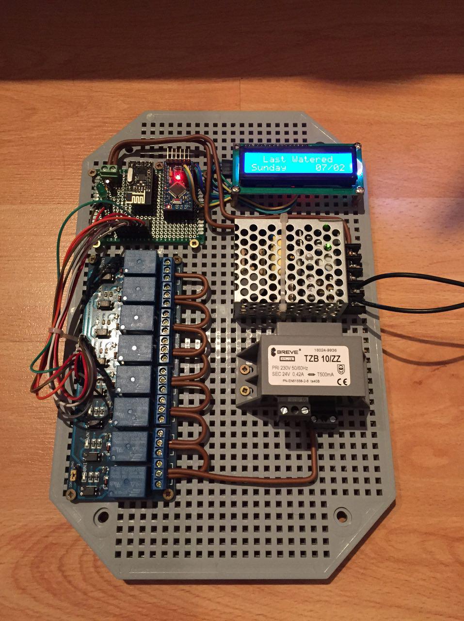
-
Hi, I've done recently this setup - it works greate with domoticz and Raspberry Pi 0.
After some tests I findout that when I plug in power - sometimes all, sometimes 3 or 4 relays are turning ON for 1second.
If that happend my 24V power adapter will be in trash. How to prevent that? Do I need to add something in code (I'm not a programmer)?try adding a delay in various places in setup() start with 5 or even 10 seconds.
-
ok, I just get back from Hackerspace. Some people fix this issue:
SN74HC595 - 13 pin (OE from datascheet) - remove GND and then add pull up 1k resistor and wire it to Arduino pin 6and software, added three lines in code:
  const int outputEnablePin = 6;

  pinMode(outputEnablePin, OUTPUT);
  digitalWrite (outputEnablePin, LOW);
put them after 190 line https://github.com/mysensors/MySensorsArduinoExamples/blob/master/examples/IrrigationController/IrrigationController.ino
should be like that:
<some code>
 //Setup Shift Register...
const int latchPin = 8;
const int clockPin = 4;
const int dataPin  = 7;
const int outputEnablePin = 6;
//
byte clock[8] = {0x0, 0xe, 0x15, 0x17, 0x11, 0xe, 0x0}; // fetching time indicator
byte raindrop[8] = {0x4, 0x4, 0xA, 0xA, 0x11, 0xE, 0x0,}; // fetching Valve Data indicator
// Set the pins on the I2C chip used for LCD connections:
//                    addr, en,rw,rs,d4,d5,d6,d7,bl,blpol
LiquidCrystal_I2C lcd(0x3F, 2, 1, 0, 4, 5, 6, 7, 3, POSITIVE);  // Set the LCD I2C address to 0x27
MySensor gw;
//
MyMessage msg1valve(CHILD_ID_SPRINKLER, V_LIGHT);
MyMessage var1valve(CHILD_ID_SPRINKLER, V_VAR1);
MyMessage var2valve(CHILD_ID_SPRINKLER, V_VAR2);
//
void setup()
{
  SERIAL_START(115200);
  DEBUG_PRINTLN(F("Initialising..."));
  pinMode(latchPin, OUTPUT);
  pinMode(clockPin, OUTPUT);
  pinMode(dataPin, OUTPUT);
  pinMode(ledPin, OUTPUT);
  pinMode(waterButtonPin, INPUT_PULLUP);
  //pinMode(waterButtonPin, INPUT);
  attachInterrupt(1, PushButton, RISING); //May need to change for your Arduino model
  digitalWrite (ledPin, HIGH);
  DEBUG_PRINTLN(F("Turning All Valves Off..."));
  updateRelays(ALL_VALVES_OFF);
  pinMode(outputEnablePin, OUTPUT);
  digitalWrite (outputEnablePin, LOW);
<some code>
If somebody can update this project in github and that fritzling draw - would be super nice.
-
@Huczas Great, thanks! Have you tested these updates? Also, can you post a link the info on hackerspace?
-
@petewill
Yes, I've tested this and it's working well!
Link to the hackerspace - HackerSpace Warsaw, they are on irc - where I talk with them, #hackerspace-pl at freenode servers. -
@petewill
Yes, I've tested this and it's working well!
Link to the hackerspace - HackerSpace Warsaw, they are on irc - where I talk with them, #hackerspace-pl at freenode servers. -
@Huczas the code has been updated in the 2.0 GitHub branch. The wiring diagram has also been updated. Thanks for the fix!
-
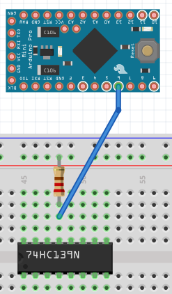
@petewill as I sad before - pull up 1k resistor and wire it to Arduino pin 6 - I mean
pull up - connect to power,
so should be 1k resistor connected with power source(that make sence with pull up) and also with pin 6. Like below:
-
I just finished building this but when I go to upload the code to my arduino i get this error
'byte clock [8]' redeclared as different kind of symbol
what does this mean ?
thanks
@bsivley Are you using the libraries from the MySensors github page (https://github.com/mysensors/MySensorsArduinoExamples/tree/master/libraries)? I just compiled it without any errors. What version of the Arduino IDE are you using? What version of MySensors are you using?
My "How To" home automation video channel: https://www.youtube.com/channel/UCq_Evyh5PQALx4m4CQuxqkA
Hello! It looks like you're interested in this conversation, but you don't have an account yet.
Getting fed up of having to scroll through the same posts each visit? When you register for an account, you'll always come back to exactly where you were before, and choose to be notified of new replies (either via email, or push notification). You'll also be able to save bookmarks and upvote posts to show your appreciation to other community members.
With your input, this post could be even better 💗
Register Login