Skip to content
  • MySensors
  • OpenHardware.io
  • Categories
  • Recent
  • Tags
  • Popular
Skins
  • Light
  • Brite
  • Cerulean
  • Cosmo
  • Flatly
  • Journal
  • Litera
  • Lumen
  • Lux
  • Materia
  • Minty
  • Morph
  • Pulse
  • Sandstone
  • Simplex
  • Sketchy
  • Spacelab
  • United
  • Yeti
  • Zephyr
  • Dark
  • Cyborg
  • Darkly
  • Quartz
  • Slate
  • Solar
  • Superhero
  • Vapor

  • Default (No Skin)
  • No Skin
Collapse
Brand Logo
  1. Home
  2. Announcements
  3. 💬 Dimmable LED Actuator

💬 Dimmable LED Actuator

Scheduled Pinned Locked Moved Announcements
59 Posts 27 Posters 13.7k Views 27 Watching
  • Oldest to Newest
  • Newest to Oldest
  • Most Votes
Reply
  • Reply as topic
Log in to reply
This topic has been deleted. Only users with topic management privileges can see it.
  • hekH Offline
    hekH Offline
    hek
    Admin
    wrote on last edited by
    #8

    Did you try just switching the pins for KNOB_ENC_PIN_x?

    korttomaK 1 Reply Last reply
    0
    • hekH hek

      Did you try just switching the pins for KNOB_ENC_PIN_x?

      korttomaK Offline
      korttomaK Offline
      korttoma
      Hero Member
      wrote on last edited by
      #9

      @hek said:

      Did you try just switching the pins for KNOB_ENC_PIN_x?

      That did the trick. Thanks!

      • Tomas
      1 Reply Last reply
      0
      • BartEB BartE

        @thazlett144 can't help to make a few comments on your sketch (sorry)

        The led the array start from 0 and prevent the double pin declaration simply subtract one on usage so
        this LED_Pin[ledid] becomes this LED_Pin[ledid-1]

        please do use wait() instead of delay(), delay is blocking MySensors communication

            // hek comment: Is this really nessesary?
            send( dimmerMsg.set(currentLevel) );
        

        Answer: Yes, controllers like Vera want feedback about the new dimlevel

        thazlett144T Offline
        thazlett144T Offline
        thazlett144
        wrote on last edited by
        #10

        @BartE Thats great thank you. I am still learning anyway so there are gaps in my knowledge :-) I knew I could do something like that -1.

        delay was part of the original example I think?

        1 Reply Last reply
        0
        • pjblinkP Offline
          pjblinkP Offline
          pjblink
          wrote on last edited by
          #11

          Hi guys,

          Struggling with this a little and think it may be hardware related. I'm using a 3.3v pro mini and it won't let the 12v LEDs go to full brightness, at max dim level they're still quite dim. I've tried this on both regular flexi LED strip and the copper-wire type LEDs (final project is based on these).

          I've tried with a different FET, an IRLB8721 and that goes to full brightness however won't switch the LEDS off completely so guessing there's a leak from that FET! I'm not sure if that's normal or not. Frustrating.

          Ideally i want the circuitry to be 3.3v as i'm already converting the 12v LED power supply down to 3.3v for the nRF. I'd rather not have a 5v and 3.3v regulator.

          Thanks,

          Patrick

          mfalkviddM ? 2 Replies Last reply
          0
          • pjblinkP pjblink

            Hi guys,

            Struggling with this a little and think it may be hardware related. I'm using a 3.3v pro mini and it won't let the 12v LEDs go to full brightness, at max dim level they're still quite dim. I've tried this on both regular flexi LED strip and the copper-wire type LEDs (final project is based on these).

            I've tried with a different FET, an IRLB8721 and that goes to full brightness however won't switch the LEDS off completely so guessing there's a leak from that FET! I'm not sure if that's normal or not. Frustrating.

            Ideally i want the circuitry to be 3.3v as i'm already converting the 12v LED power supply down to 3.3v for the nRF. I'd rather not have a 5v and 3.3v regulator.

            Thanks,

            Patrick

            mfalkviddM Offline
            mfalkviddM Offline
            mfalkvidd
            Mod
            wrote on last edited by
            #12

            @pjblink I had the same problem in https://forum.mysensors.org/topic/2335/controlling-leds-with-the-irlz44n/ and another community member had something similar: https://forum.mysensors.org/topic/2335/controlling-leds-with-the-irlz44n/

            The solution seems to be to buy new mosfets and hope that they work properly.

            pjblinkP 1 Reply Last reply
            0
            • mfalkviddM mfalkvidd

              @pjblink I had the same problem in https://forum.mysensors.org/topic/2335/controlling-leds-with-the-irlz44n/ and another community member had something similar: https://forum.mysensors.org/topic/2335/controlling-leds-with-the-irlz44n/

              The solution seems to be to buy new mosfets and hope that they work properly.

              pjblinkP Offline
              pjblinkP Offline
              pjblink
              wrote on last edited by
              #13

              @mfalkvidd So keep trying IRLZ44N FETs?

              mfalkviddM 1 Reply Last reply
              0
              • pjblinkP pjblink

                @mfalkvidd So keep trying IRLZ44N FETs?

                mfalkviddM Offline
                mfalkviddM Offline
                mfalkvidd
                Mod
                wrote on last edited by
                #14

                @pjblink probably. Several people have reported their IRLZ44N opening fully at 3.3V.

                1 Reply Last reply
                0
                • korttomaK Offline
                  korttomaK Offline
                  korttoma
                  Hero Member
                  wrote on last edited by korttoma
                  #15

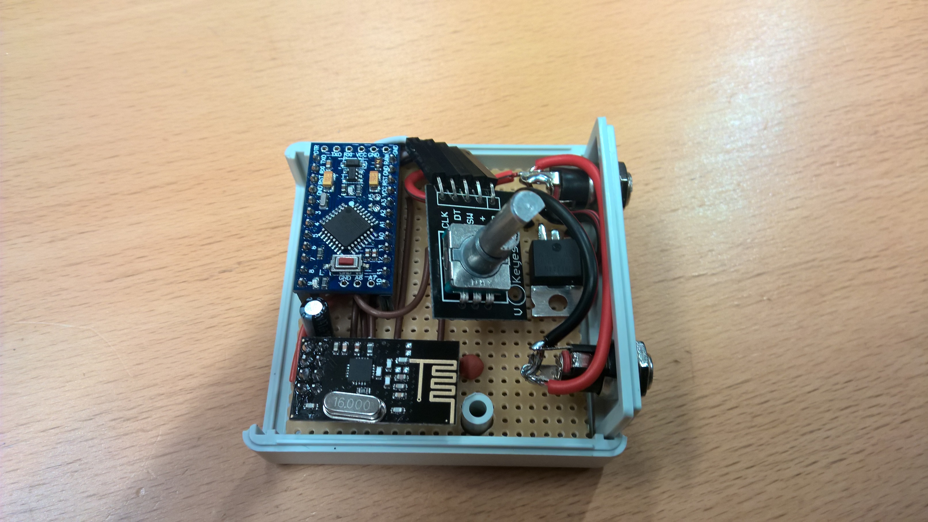
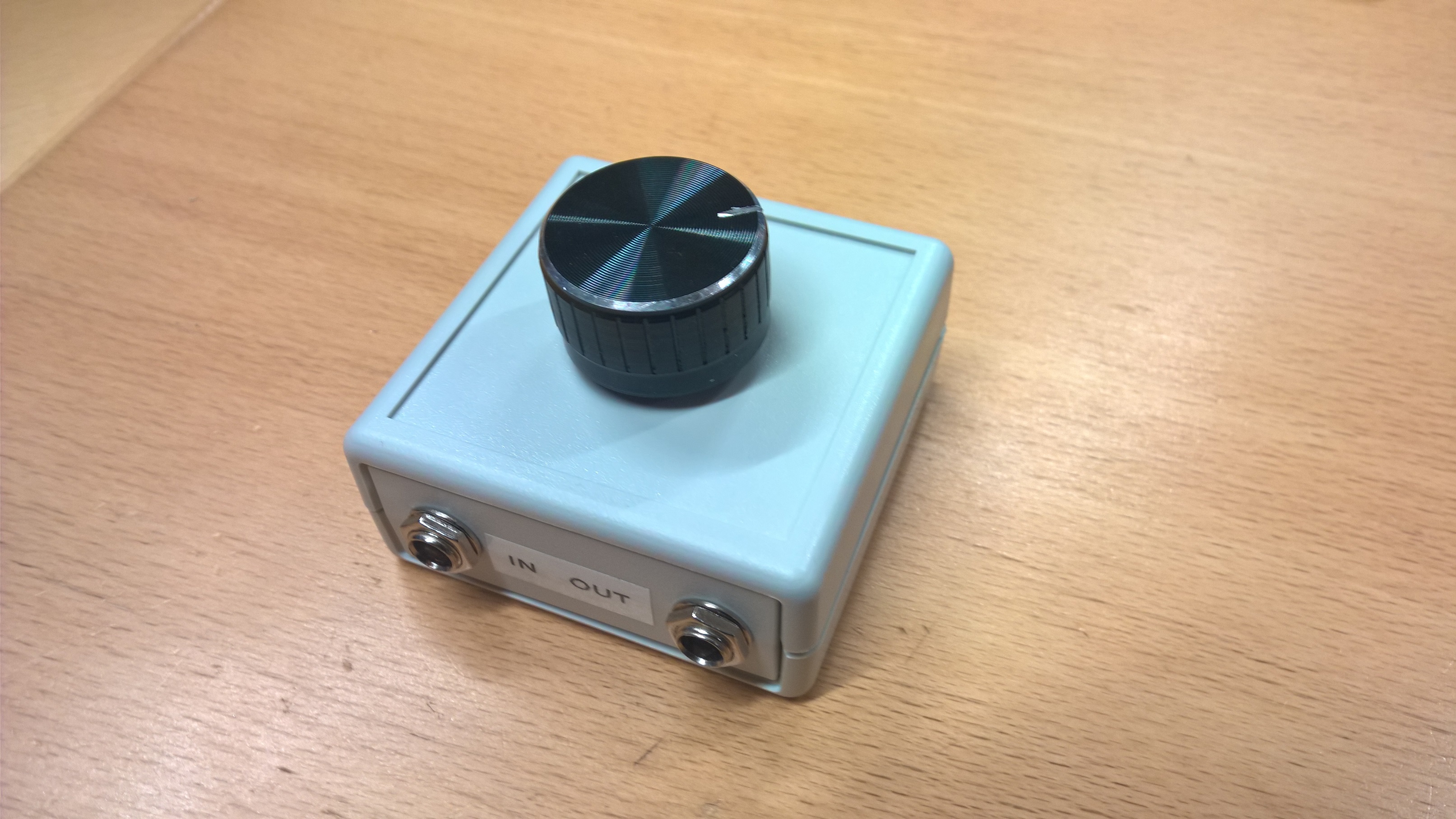
                  Inspirational pictures from my Dimmable LED Actuator with rotary encoder device I made for my sons bedside lamp.
                  Running this at 12VDC. His lamp had a G9 socket so I just broke apart the G9 LED bulb and soldered some G4 12VDC LED lights like these to it and replaces the "Dumb" switch with a 5mm DC plug. It turned out so nice that I think I will MySensor my own bedside lamp also.

                  Edit: btw, I found the nice big knobs from here -> eBay

                  0_1476680417320_WP_20161014_07_07_53.jpg

                  0_1476680429390_WP_20161014_07_11_47.jpg

                  • Tomas
                  1 Reply Last reply
                  3
                  • korttomaK Offline
                    korttomaK Offline
                    korttoma
                    Hero Member
                    wrote on last edited by
                    #16

                    Bahh.. I had the 12VDC connected directly to the RAW pin on the Arduino Pro mini and yesterday it failed.
                    I should have known better. Now added a 5V regulator to the device and a new 5V Pro Mini.

                    • Tomas
                    1 Reply Last reply
                    0
                    • MalmQM Offline
                      MalmQM Offline
                      MalmQ
                      wrote on last edited by
                      #17

                      Hi all
                      I love the mysensors project. I have made a lot of sensors by now. Now I would like to control these LED-lights with a dimmer node:
                      http://www.siriushome.dk/product/50200/ (in danish)
                      The specs. for the LEDs are 6W@80V.
                      I have two questions that I hope you can help me with.
                      A) What is the easiest way to drive an arduinonode from 80v. Is a DC/DC converter the only way?
                      B) What mosfet would you suggest using for controling the LEDs?

                      I hope you can help. Many thanks.

                      // MalmQ

                      1 Reply Last reply
                      0
                      • pjblinkP pjblink

                        Hi guys,

                        Struggling with this a little and think it may be hardware related. I'm using a 3.3v pro mini and it won't let the 12v LEDs go to full brightness, at max dim level they're still quite dim. I've tried this on both regular flexi LED strip and the copper-wire type LEDs (final project is based on these).

                        I've tried with a different FET, an IRLB8721 and that goes to full brightness however won't switch the LEDS off completely so guessing there's a leak from that FET! I'm not sure if that's normal or not. Frustrating.

                        Ideally i want the circuitry to be 3.3v as i'm already converting the 12v LED power supply down to 3.3v for the nRF. I'd rather not have a 5v and 3.3v regulator.

                        Thanks,

                        Patrick

                        ? Offline
                        ? Offline
                        A Former User
                        wrote on last edited by A Former User
                        #18

                        @pjblink the irlzn44n is very sensitive to over heat during solder, I have lost some of them during soldering :) please be careful

                        1 Reply Last reply
                        0
                        • CreakyC Offline
                          CreakyC Offline
                          Creaky
                          wrote on last edited by
                          #19

                          Hi!

                          I'd like to use this sketch with a 5V Arduino Nano, do I need to use another type of MOSFET for this?
                          From the OP I gather that the IRLZ44N is used because of the lower gate threshold in combination with the 3.3v operating voltage, but won't the IRLZ44N gate be saturated very quickly when using 5v?

                          Creaky

                          mfalkviddM 1 Reply Last reply
                          0
                          • CreakyC Creaky

                            Hi!

                            I'd like to use this sketch with a 5V Arduino Nano, do I need to use another type of MOSFET for this?
                            From the OP I gather that the IRLZ44N is used because of the lower gate threshold in combination with the 3.3v operating voltage, but won't the IRLZ44N gate be saturated very quickly when using 5v?

                            Creaky

                            mfalkviddM Offline
                            mfalkviddM Offline
                            mfalkvidd
                            Mod
                            wrote on last edited by mfalkvidd
                            #20

                            @Creaky the dimmer uses PWM to control the light level, so the mosfet is always either in cutoff or fully saturated. So using IRLz44N with 5V will work just as well as 3.3V.

                            CreakyC 2 Replies Last reply
                            0
                            • mfalkviddM mfalkvidd

                              @Creaky the dimmer uses PWM to control the light level, so the mosfet is always either in cutoff or fully saturated. So using IRLz44N with 5V will work just as well as 3.3V.

                              CreakyC Offline
                              CreakyC Offline
                              Creaky
                              wrote on last edited by
                              #21

                              @mfalkvidd Thanks for the reply!

                              1 Reply Last reply
                              1
                              • mfalkviddM mfalkvidd

                                @Creaky the dimmer uses PWM to control the light level, so the mosfet is always either in cutoff or fully saturated. So using IRLz44N with 5V will work just as well as 3.3V.

                                CreakyC Offline
                                CreakyC Offline
                                Creaky
                                wrote on last edited by
                                #22

                                @mfalkvidd Just so you know, there is no PWM involved in this sketch. I've just build this setup/node and it works great. You can see that the LED are continuously fed and brightness is changed by changing the voltage to the LEDs through the MOSFET.

                                mfalkviddM 1 Reply Last reply
                                0
                                • CreakyC Creaky

                                  @mfalkvidd Just so you know, there is no PWM involved in this sketch. I've just build this setup/node and it works great. You can see that the LED are continuously fed and brightness is changed by changing the voltage to the LEDs through the MOSFET.

                                  mfalkviddM Offline
                                  mfalkviddM Offline
                                  mfalkvidd
                                  Mod
                                  wrote on last edited by mfalkvidd
                                  #23

                                  @Creaky the sketch linked in the first post uses pwm. But you might be using some other sketch?

                                  CreakyC 1 Reply Last reply
                                  0
                                  • riochickenR Offline
                                    riochickenR Offline
                                    riochicken
                                    wrote on last edited by
                                    #24

                                    It might be a very nice idea to use neopixels with this, a little expensive though when using a lot of LED's but still it's possible to dim them just by using code.. I am afraid I am not able to do that and it was just a small thought... :)

                                    1 Reply Last reply
                                    0
                                    • mfalkviddM mfalkvidd

                                      @Creaky the sketch linked in the first post uses pwm. But you might be using some other sketch?

                                      CreakyC Offline
                                      CreakyC Offline
                                      Creaky
                                      wrote on last edited by Creaky
                                      #25

                                      @mfalkvidd Yikes, you're right! I drew my conclusion too soon and only by watching the LED strip at max brightness. At max brightness the switching frequency is so high it is no longer perceptible by the eye. Mea culpa...

                                      mfalkviddM 1 Reply Last reply
                                      0
                                      • CreakyC Creaky

                                        @mfalkvidd Yikes, you're right! I drew my conclusion too soon and only by watching the LED strip at max brightness. At max brightness the switching frequency is so high it is no longer perceptible by the eye. Mea culpa...

                                        mfalkviddM Offline
                                        mfalkviddM Offline
                                        mfalkvidd
                                        Mod
                                        wrote on last edited by
                                        #26

                                        @Creaky yes the switching is pretty quick. I guess that's the whole idea :) I have noticed a refraction pattern in the kitchen sink when using a thin jet of water though.

                                        The analogWrite function in Arduino is very poorly named, since it doesn't really write an analog value. But I guess it is hard to change now.

                                        1 Reply Last reply
                                        0
                                        • A Offline
                                          A Offline
                                          antonholmstedt
                                          wrote on last edited by
                                          #27

                                          I plan to use a LED strip as a closet light, controlled by a magnetic door switch, and of course also controllable in Domoticz. What would be the right way to write the code, should the pro mini send the state of the magnetic switch to the controller and then let the controller turn on the light, or is it easier to let the pro mini turn on the light directly and then report the state back to the controller? Big difference in delay?

                                          1 Reply Last reply
                                          0
                                          Reply
                                          • Reply as topic
                                          Log in to reply
                                          • Oldest to Newest
                                          • Newest to Oldest
                                          • Most Votes


                                          18

                                          Online

                                          11.7k

                                          Users

                                          11.2k

                                          Topics

                                          113.0k

                                          Posts


                                          Copyright 2025 TBD   |   Forum Guidelines   |   Privacy Policy   |   Terms of Service
                                          • Login

                                          • Don't have an account? Register

                                          • Login or register to search.
                                          • First post
                                            Last post
                                          0
                                          • MySensors
                                          • OpenHardware.io
                                          • Categories
                                          • Recent
                                          • Tags
                                          • Popular