Easy/Newbie PCB for MySensors
-
Has anyone tried one of these boosters:
- They are sometimes much cheaper than the 3.3v ones
- Since they are adjustable, I would think you could optimize the output voltage for maximum battery.
I'm not sure, is there a problem using them with the PCB boards? I imagine the input and output ground would have to be connected together.
Thanks!
@ileneken3 - sorry never tried them.
The footprint looks different from the PCB so you need to connect this with wires to the PCB.Controller: Proxmox VM - Home Assistant
MySensors GW: Arduino Uno - W5100 Ethernet, Gw Shield Nrf24l01+ 2,4Ghz
MySensors GW: Arduino Uno - Gw Shield RFM69, 433mhz
RFLink GW - Arduino Mega + RFLink Shield, 433mhz -
@ileneken3 - sorry never tried them.
The footprint looks different from the PCB so you need to connect this with wires to the PCB.I took a chance and tried these boosters. After adjusting the pot to boost to 3.3V, and using wires to connect, they seem to work the same as the "recommended" ones. I am hoping they produce less noise for the radio - I seem to have trouble with that, even with adding the capacitors. (Maybe my radios are not good).
Another experiment - boosting them to just over the 2.8V fuse limit. I would think that would be more energy efficient. -
@ileneken3 in my experienxe the 3.3v booster gives a lot of problem with radio :-)
-
@ileneken3 in my experienxe the 3.3v booster gives a lot of problem with radio :-)
@jumping - correct, if you can make a node without its better for the radio but its easier to do with a booster, radio and a pre-made Arduino pro mini.
Controller: Proxmox VM - Home Assistant
MySensors GW: Arduino Uno - W5100 Ethernet, Gw Shield Nrf24l01+ 2,4Ghz
MySensors GW: Arduino Uno - Gw Shield RFM69, 433mhz
RFLink GW - Arduino Mega + RFLink Shield, 433mhz -
@jumping - correct, if you can make a node without its better for the radio but its easier to do with a booster, radio and a pre-made Arduino pro mini.
hi @sundberg84, if you have some free time you can see my post about a "new" PCB
https://forum.mysensors.org/topic/5314/pcbs-for-battery-based-sensor :-) -
@jumping - correct, if you can make a node without its better for the radio but its easier to do with a booster, radio and a pre-made Arduino pro mini.
It's definitely easier with a booster - but not cheaper or more reliable. (Why does the booster cost more than the Arduino?)
Everything is about tradeoff's. When you solve one problem, it can easily introduce another. At first, I ignored the whole booster thing. But after a lot of experiments, I ended up with a pile of 1.35 V batteries. So I tried the booster, and ended up with transmission problems (partially solved by capacitors). So then I tried changing the bootloader (1Mhz, no brown out), and it seems to be OK - but I know there will be other problems. Example: I now need to boost to 3.3V for sensors that require it. Also, are there compatibility problems with mysensors?
Even still, thanks for the great board - I've had a lot of fun and learned a lot with it!
-
It's definitely easier with a booster - but not cheaper or more reliable. (Why does the booster cost more than the Arduino?)
Everything is about tradeoff's. When you solve one problem, it can easily introduce another. At first, I ignored the whole booster thing. But after a lot of experiments, I ended up with a pile of 1.35 V batteries. So I tried the booster, and ended up with transmission problems (partially solved by capacitors). So then I tried changing the bootloader (1Mhz, no brown out), and it seems to be OK - but I know there will be other problems. Example: I now need to boost to 3.3V for sensors that require it. Also, are there compatibility problems with mysensors?
Even still, thanks for the great board - I've had a lot of fun and learned a lot with it!
@ileneken3 - you are so right, and that is the fun with electronics! There is no right or wrong (more or less)!
Newbie/Easy PCB is what it sounds like and my only aim is to make it as easy as possible. Im happy to evaluate it but at the moment booster and a few non compatible sensors is the price i pay.I have probably 15 of these PCB with boosters now, and yes - there are times when the booster makes it unreliable but most of the times it works. I have maybe trashed 5 nodes in all which is fair less amount that I had to trash soldering wires. I have also tried bare atmegas in different shapes and even with them there are problems (not including flashing bootloaders and stuff you dont have to do with EasyPCB).
We also needs to remember this is DIY, not factory manufactured which can introduce alof of errors. We learn as we go and I hope EasyPCB can be a great platform for new people like you said. Nice to hear, thank you!
-
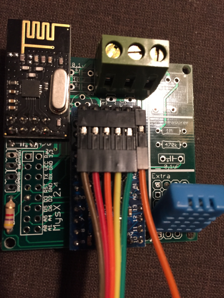
Yesterday I have received Rev 9 of Newbie PCB board. I am a newbie and I purchased this board to make building easier. I have soldered a radio and Arduino Pro Mini 3.3 V to it and the radio module with a 47uF cap. The power is supplied using the FTD232 board. Because the radio module is not powered using the 3.3V of arduino I wired this using a separate wire. I also connected a DTH 11 with the resistor on the board (4K7). I used a test sketch to read the DTH 11 and this is working well.
When I load the MySensors sketch I get a radio failure. I have no Idea what this is? Bad wiring, not correct power?? Anyone can help me started?
0 MCO:BGN:INIT NODE,CP=RNNNA--,VER=2.1.1 4 TSM:INIT 4 TSF:WUR:MS=0 12 !TSM:INIT:TSP FAIL 14 TSM:FAIL:CNT=1 16 TSM:FAIL:PDT 10018 TSM:FAIL:RE-INIT 10020 TSM:INIT 10027 !TSM:INIT:TSP FAIL 10031 TSM:FAIL:CNT=2 10033 TSM:FAIL:PDT``` -
Yesterday I have received Rev 9 of Newbie PCB board. I am a newbie and I purchased this board to make building easier. I have soldered a radio and Arduino Pro Mini 3.3 V to it and the radio module with a 47uF cap. The power is supplied using the FTD232 board. Because the radio module is not powered using the 3.3V of arduino I wired this using a separate wire. I also connected a DTH 11 with the resistor on the board (4K7). I used a test sketch to read the DTH 11 and this is working well.
When I load the MySensors sketch I get a radio failure. I have no Idea what this is? Bad wiring, not correct power?? Anyone can help me started?
0 MCO:BGN:INIT NODE,CP=RNNNA--,VER=2.1.1 4 TSM:INIT 4 TSF:WUR:MS=0 12 !TSM:INIT:TSP FAIL 14 TSM:FAIL:CNT=1 16 TSM:FAIL:PDT 10018 TSM:FAIL:RE-INIT 10020 TSM:INIT 10027 !TSM:INIT:TSP FAIL 10031 TSM:FAIL:CNT=2 10033 TSM:FAIL:PDT```@martim said in Easy/Newbie PCB for MySensors:
Because the radio module is not powered using the 3.3V of arduino I wired this using a separate wire.
Can you show a picture of your setup and give more explanation on this sentence ? This part about connection of the radio smells fishy ;)
It seems the radio cannot be initialized, so I suppose the power supplied to it is not correct, but I'm not sure of what you did. -
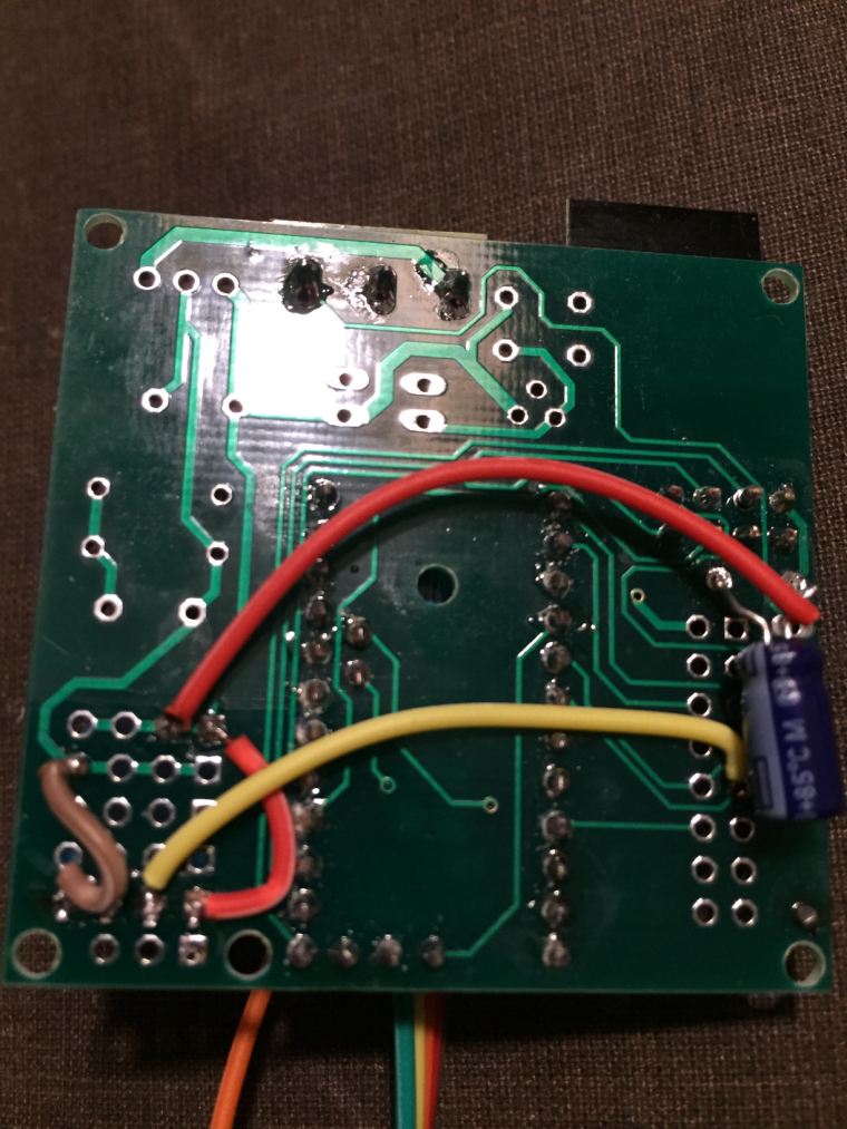
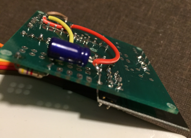
This is the front part. The connected cable goes to the FTD232 which also is currently the power supply.
 !
!The red wire on the back plane connects the plus from arduino to the plus for the radio (soldered on the + of cap)
0_1486835943373_IMG_3546.JPG !Try to zoom in.
0_1486835954003_zoomed.png -
This is the front part. The connected cable goes to the FTD232 which also is currently the power supply.
!The red wire on the back plane connects the plus from arduino to the plus for the radio (soldered on the + of cap)
0_1486835943373_IMG_3546.JPG !Try to zoom in.
0_1486835954003_zoomed.png@martim - read the insctructions again.
If you are using the board with a 3.3v arduino and battery you need to connect the BAT jumper and use a booster.If you are using a 3.3 arduino with a regulated power you can add a jumper/wire over the booster and connect the BAT jumper.
-
@martim - read the insctructions again.
If you are using the board with a 3.3v arduino and battery you need to connect the BAT jumper and use a booster.If you are using a 3.3 arduino with a regulated power you can add a jumper/wire over the booster and connect the BAT jumper.
@sundberg84
Ok, Thanks I will try the second suggestion. (my booster is still not delivered and hard to get at the moment :() -
Found one issue. On the PCB board the was a very small broken wire. I think the postman was not very careful with it. At least I have some better logging but still not there.
How can I solve this one?
0 MCO:BGN:INIT NODE,CP=RNNNA--,VER=2.1.1
4 TSM:INIT
4 TSF:WUR:MS=0
12 TSM:INIT:TSP OK
14 TSM:INIT:STATID=20
16 TSF:SID:OK,ID=20
18 TSM:FPAR
55 TSF:MSG:SEND,20-20-255-255,s=255,c=3,t=7,pt=0,l=0,sg=0,ft=0,st=OK:
2064 !TSM:FPAR:NO REPLY
2066 TSM:FPAR
2103 TSF:MSG:SEND,20-20-255-255,s=255,c=3,t=7,pt=0,l=0,sg=0,ft=0,st=OK:
4112 !TSM:FPAR:NO REPLY
4114 TSM:FPAR
4151 TSF:MSG:SEND,20-20-255-255,s=255,c=3,t=7,pt=0,l=0,sg=0,ft=0,st=OK:
6160 !TSM:FPAR:NO REPLY
6162 TSM:FPAR
6199 TSF:MSG:SEND,20-20-255-255,s=255,c=3,t=7,pt=0,l=0,sg=0,ft=0,st=OK:
8208 !TSM:FPAR:FAIL
8210 TSM:FAIL:CNT=1
8212 TSM:FAIL:PDT
Does this mean the gateway does not reply? It does with other sensors?
-
Found one issue. On the PCB board the was a very small broken wire. I think the postman was not very careful with it. At least I have some better logging but still not there.
How can I solve this one?
0 MCO:BGN:INIT NODE,CP=RNNNA--,VER=2.1.1
4 TSM:INIT
4 TSF:WUR:MS=0
12 TSM:INIT:TSP OK
14 TSM:INIT:STATID=20
16 TSF:SID:OK,ID=20
18 TSM:FPAR
55 TSF:MSG:SEND,20-20-255-255,s=255,c=3,t=7,pt=0,l=0,sg=0,ft=0,st=OK:
2064 !TSM:FPAR:NO REPLY
2066 TSM:FPAR
2103 TSF:MSG:SEND,20-20-255-255,s=255,c=3,t=7,pt=0,l=0,sg=0,ft=0,st=OK:
4112 !TSM:FPAR:NO REPLY
4114 TSM:FPAR
4151 TSF:MSG:SEND,20-20-255-255,s=255,c=3,t=7,pt=0,l=0,sg=0,ft=0,st=OK:
6160 !TSM:FPAR:NO REPLY
6162 TSM:FPAR
6199 TSF:MSG:SEND,20-20-255-255,s=255,c=3,t=7,pt=0,l=0,sg=0,ft=0,st=OK:
8208 !TSM:FPAR:FAIL
8210 TSM:FAIL:CNT=1
8212 TSM:FAIL:PDT
Does this mean the gateway does not reply? It does with other sensors?
@martim - yes, it doesnt get the connection to the GW as it wants... might be node or gw. Do you have caps on both?
-
Awesome board!!!
How do I access A2, A3 and D8?Thanks a lot
-
Awesome board!!!
How do I access A2, A3 and D8?Thanks a lot
@hiddenuser - they are not accesses through the PCB:
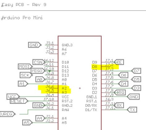
You need to solder a wire on the Pro Mini and run somewhere, like the prototyping area.
-
@hiddenuser - they are not accesses through the PCB:
You need to solder a wire on the Pro Mini and run somewhere, like the prototyping area.
@sundberg84 Thanks a lot.... My ebay seller sent me a Atmega168 5v. I have noticed that you boards supports 5v version too. Would I be able to power it using raw (12v).
Thanks a lot .
-
@sundberg84 Thanks a lot.... My ebay seller sent me a Atmega168 5v. I have noticed that you boards supports 5v version too. Would I be able to power it using raw (12v).
Thanks a lot .
@hiddenuser - as long as the voltage divider on the board supports 12v that will work. A warning on the cheap chinese stuff is that this voltage regulator is bad and might fry.
-
@hiddenuser - as long as the voltage divider on the board supports 12v that will work. A warning on the cheap chinese stuff is that this voltage regulator is bad and might fry.
@sundberg84 - thanks for your board, it seems to be almost exactly what I was looking for! What do you think would be the best way to adjust it if I need to boost the batteries not only to 3.3V, but also to 5V to run the pir sensor?
Hello! It looks like you're interested in this conversation, but you don't have an account yet.
Getting fed up of having to scroll through the same posts each visit? When you register for an account, you'll always come back to exactly where you were before, and choose to be notified of new replies (either via email, or push notification). You'll also be able to save bookmarks and upvote posts to show your appreciation to other community members.
With your input, this post could be even better 💗
Register Login