Sensor "persistence"?
-
So this is the gateway code:
/** * The MySensors Arduino library handles the wireless radio link and protocol * between your home built sensors/actuators and HA controller of choice. * The sensors forms a self healing radio network with optional repeaters. Each * repeater and gateway builds a routing tables in EEPROM which keeps track of the * network topology allowing messages to be routed to nodes. * * Created by Henrik Ekblad <henrik.ekblad@mysensors.org> * Copyright (C) 2013-2015 Sensnology AB * Full contributor list: https://github.com/mysensors/Arduino/graphs/contributors * * Documentation: http://www.mysensors.org * Support Forum: http://forum.mysensors.org * * This program is free software; you can redistribute it and/or * modify it under the terms of the GNU General Public License * version 2 as published by the Free Software Foundation. * ******************************* * * DESCRIPTION * The ArduinoGateway prints data received from sensors on the serial link. * The gateway accepts input on seral which will be sent out on radio network. * * The GW code is designed for Arduino Nano 328p / 16MHz * * Wire connections (OPTIONAL): * - Inclusion button should be connected between digital pin 3 and GND * - RX/TX/ERR leds need to be connected between +5V (anode) and digital pin 6/5/4 with resistor 270-330R in a series * * LEDs (OPTIONAL): * - To use the feature, uncomment any of the MY_DEFAULT_xx_LED_PINs * - RX (green) - blink fast on radio message recieved. In inclusion mode will blink fast only on presentation recieved * - TX (yellow) - blink fast on radio message transmitted. In inclusion mode will blink slowly * - ERR (red) - fast blink on error during transmission error or recieve crc error * */ // Enable debug prints to serial monitor #define MY_DEBUG // Enable and select radio type attached #define MY_RADIO_NRF24 //#define MY_RADIO_RFM69 // Set LOW transmit power level as default, if you have an amplified NRF-module and // power your radio separately with a good regulator you can turn up PA level. #define MY_RF24_PA_LEVEL RF24_PA_LOW // Enable serial gateway #define MY_GATEWAY_SERIAL // Define a lower baud rate for Arduino's running on 8 MHz (Arduino Pro Mini 3.3V & SenseBender) #if F_CPU == 8000000L #define MY_BAUD_RATE 38400 #endif // Enable inclusion mode #define MY_INCLUSION_MODE_FEATURE // Enable Inclusion mode button on gateway //#define MY_INCLUSION_BUTTON_FEATURE // Inverses behavior of inclusion button (if using external pullup) //#define MY_INCLUSION_BUTTON_EXTERNAL_PULLUP // Set inclusion mode duration (in seconds) #define MY_INCLUSION_MODE_DURATION 60 // Digital pin used for inclusion mode button //#define MY_INCLUSION_MODE_BUTTON_PIN 3 // Set blinking period #define MY_DEFAULT_LED_BLINK_PERIOD 300 // Inverses the behavior of leds #define MY_WITH_LEDS_BLINKING_INVERSE // Flash leds on rx/tx/err // Uncomment to override default HW configurations #define MY_DEFAULT_ERR_LED_PIN 4 // Error led pin #define MY_DEFAULT_RX_LED_PIN 6 // Receive led pin #define MY_DEFAULT_TX_LED_PIN 5 // the PCB, on board LED #include <MySensors.h> void setup() { // Setup locally attached sensors } void presentation() { // Present locally attached sensors } void loop() { // Send locally attached sensor data here }``` -
And this is my temperature sensor code (I'm using a thermistor):
// Enable debug prints to serial monitor #define MY_DEBUG #define MY_RADIO_NRF24 #include <MySensors.h> #define NODE_ID 0 int _nominal_resistor = 4700; int _nominal_temperature = 25; int _b_coefficient = 3950; int _series_resistor = 5630; int _pin = 1; MyMessage msg(NODE_ID, V_TEMP); //uint8_t value = OPEN; int8_t temp = 25; void setup() { Serial.begin(115200); } void presentation() { // Send the sketch version information to the gateway and Controller sendSketchInfo("Thermistor", "1.0"); present(NODE_ID, S_TEMP); } void loop() { temp = measure_temperature(); Serial.println(temp); send(msg.set(temp)); sleep(3000); } int8_t measure_temperature() { // read the voltage across the thermistor float adc = analogRead(_pin); // calculate the temperature float reading = (1023 / adc) - 1; reading = _series_resistor / reading; float temperature; temperature = reading / _nominal_resistor; // (R/Ro) temperature = log(temperature); // ln(R/Ro) temperature /= _b_coefficient; // 1/B * ln(R/Ro) temperature += 1.0 / (_nominal_temperature + 273.15); // + (1/To) temperature = 1.0 / temperature; // Invert temperature -= 273.15; // convert to C if (! getControllerConfig().isMetric) temperature = temperature * 1.8 + 32; return int8_t(temperature); }``` I start Domoticz, enter the Gateway setup and delete every node while the sensor is powered off. I power on the sensor (connect the USB cable to my laptop) and nothing happens, I click refresh on the nodes but no nodes shows up, the RX and TX LEDs on the gateway do not blink. Then I reflash (upload) the code above and suddenly the RX and TX LEDs on the Gateway start blinking and Domoticz recognizes my sensor. It is like if I power off the sensor it will not be recognized unless I upload the sensor code again. -
Sorry ... still learning how to use the Insert Code Block :-)
I start Domoticz, enter the Gateway setup and delete every node while the sensor is powered off.
I power on the sensor (connect the USB cable to my laptop) and nothing happens, I click refresh on the nodes but no nodes shows up, the RX and TX LEDs on the gateway do not blink.
Then I reflash (upload) the code above and suddenly the RX and TX LEDs on the Gateway start blinking and Domoticz recognizes my sensor.
It is like if I power off the sensor it will not be recognized unless I upload the sensor code again. -
Try a simpler approach, use a serial terminal to access the gateway, and check the messages that is coming in there.
Next check the serial port on the node, and check if it indicates any errors etc, both on first power up, and on second/third/fourth etc.
-
OK, I tried to power ON the sensor 5 times, I opened the Arduino serial monitor every time and waited a couple of minutes, the terminal window was empty every time like the sensor has no serial output.
Sixth time I hit the upload button in Arduino and in a few seconds the sensor starts working and this is what I can see in the terminal window:0 MCO:BGN:INIT NODE,CP=RNNNA--,VER=2.1.1 3 TSM:INIT 4 TSF:WUR:MS=0 11 TSM:INIT:TSP OK 13 TSF:SID:OK,ID=2 14 TSM:FPAR 51 TSF:MSG:SEND,2-2-255-255,s=255,c=3,t=7,pt=0,l=0,sg=0,ft=0,st=OK: 411 TSF:MSG:READ,0-0-2,s=255,c=3,t=8,pt=1,l=1,sg=0:0 416 TSF:MSG:FPAR OK,ID=0,D=1 2058 TSM:FPAR:OK 2059 TSM:ID 2060 TSM:ID:OK 2062 TSM:UPL 2065 TSF:MSG:SEND,2-2-0-0,s=255,c=3,t=24,pt=1,l=1,sg=0,ft=0,st=OK:1 2071 TSF:MSG:READ,0-0-2,s=255,c=3,t=25,pt=1,l=1,sg=0:1 2076 TSF:MSG:PONG RECV,HP=1 2078 TSM:UPL:OK 2080 TSM:READY:ID=2,PAR=0,DIS=1 2084 TSF:MSG:SEND,2-2-0-0,s=255,c=3,t=15,pt=6,l=2,sg=0,ft=0,st=OK:0100 2092 TSF:MSG:READ,0-0-2,s=255,c=3,t=15,pt=6,l=2,sg=0:0100 2099 TSF:MSG:SEND,2-2-0-0,s=255,c=0,t=17,pt=0,l=5,sg=0,ft=0,st=OK:2.1.1 2107 TSF:MSG:SEND,2-2-0-0,s=255,c=3,t=6,pt=1,l=1,sg=0,ft=0,st=OK:0 2113 TSF:MSG:READ,0-0-2,s=255,c=3,t=6,pt=0,l=1,sg=0:M 2120 TSF:MSG:SEND,2-2-0-0,s=255,c=3,t=11,pt=0,l=10,sg=0,ft=0,st=OK:Thermistor 2129 TSF:MSG:SEND,2-2-0-0,s=255,c=3,t=12,pt=0,l=3,sg=0,ft=0,st=OK:1.0 2138 TSF:MSG:SEND,2-2-0-0,s=0,c=0,t=6,pt=0,l=0,sg=0,ft=0,st=OK: 2143 MCO:REG:REQ 2147 TSF:MSG:SEND,2-2-0-0,s=255,c=3,t=26,pt=1,l=1,sg=0,ft=0,st=OK:2 2153 TSF:MSG:READ,0-0-2,s=255,c=3,t=27,pt=1,l=1,sg=0:1 2158 MCO:PIM:NODE REG=1 2160 MCO:BGN:STP 2162 MCO:BGN:INIT OK,TSP=1 27 2166 TSF:MSG:SEND,2-2-0-0,s=0,c=1,t=0,pt=2,l=2,sg=0,ft=0,st=OK:27 2172 MCO:SLP:MS=3000,SMS=0,I1=255,M1=255,I2=255,M2=255 2178 MCO:SLP:TPD 2180 MCO:SLP:WUP=-1 27 2184 TSF:MSG:SEND,2-2-0-0,s=0,c=1,t=0,pt=2,l=2,sg=0,ft=0,st=OK:27 2190 MCO:SLP:MS=3000,SMS=0,I1=255,M1=255,I2=255,M2=255 2195 MCO:SLP:TPD 2197 MCO:SLP:WUP=-1 27 2201 TSF:MSG:SEND,2-2-0-0,s=0,c=1,t=0,pt=2,l=2,sg=0,ft=0,st=OK:27 2207 MCO:SLP:MS=3000,SMS=0,I1=255,M1=255,I2=255,M2=255 2212 MCO:SLP:TPD 2214 MCO:SLP:WUP=-1 27 2219 TSF:MSG:SEND,2-2-0-0,s=0,c=1,t=0,pt=2,l=2,sg=0,ft=0,st=OK:27 2225 MCO:SLP:MS=3000,SMS=0,I1=255,M1=255,I2=255,M2=255 2230 MCO:SLP:TPD 2231 MCO:SLP:WUP=-1``` -
The node is an Arduino Mini - it is not an Arduino Mini Pro as reccomended, true!
But I'll try soon with an Arduino Nano as a node.
The gateway is an Arduino nano.
on The gateway side the serial monitor only shows0;255;3;0;14;Gateway startup complete. 0;255;0;0;18;2.1.1no matter how many times I power ON and OFF the sensor.
But after I reflash the sensor then the Gateway serial output is:0;255;3;0;14;Gateway startup complete. 0;255;0;0;18;2.1.1 2;255;3;0;11;Thermistor 2;255;3;0;12;1.0 2;0;0;0;6; 2;0;1;0;0;27``` -
Just a thought..
Program a simple blinking sketch in your node, see if the LED is blinking (this is without mysensors at all!)
Now try powercycling it a couple of times, does it start blinking?
If not, then there is a problem with your arduino mini.
-
Amazing! You were absolutely right! I tried a simple LED blink like below, it only works once after the code upload. No matter how many times I power cycle after that, it will not work any more. What could be wrong with this Arduino Mini? It is the original Arduino Mini from Farnell ...
/* Blink Turns on an LED on for one second, then off for one second, repeatedly. Most Arduinos have an on-board LED you can control. On the UNO, MEGA and ZERO it is attached to digital pin 13, on MKR1000 on pin 6. LED_BUILTIN is set to the correct LED pin independent of which board is used. If you want to know what pin the on-board LED is connected to on your Arduino model, check the Technical Specs of your board at https://www.arduino.cc/en/Main/Products This example code is in the public domain. modified 8 May 2014 by Scott Fitzgerald modified 2 Sep 2016 by Arturo Guadalupi modified 8 Sep 2016 by Colby Newman */ // the setup function runs once when you press reset or power the board void setup() { // initialize digital pin LED_BUILTIN as an output. pinMode(8, OUTPUT); } // the loop function runs over and over again forever void loop() { digitalWrite(8, HIGH); // turn the LED on (HIGH is the voltage level) delay(1000); // wait for a second digitalWrite(8, LOW); // turn the LED off by making the voltage LOW delay(1000); // wait for a second }``` -
Forgot to tell I have a few such Arduino Mini, all have the same issue!
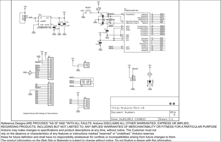
Might have something to do with both the way I have connected the power and the reset, like here, "Connecting the Arduino Mini and Mini USB Adapter":https://www.arduino.cc/en/Guide/ArduinoMini
Power to the Arduino (+5V) comes from the USB Adapter while reset goes through a capacitor.
I will abandon this setup and use a nano based sensor for now. -
Yes, I did, no change.
I have removed the capacitor on the RESET pin and I have pressed the RESET button on the Mini, nothing happens to my surprise.
I shall try to use a different 5V power supply instead of supplying the Mini from the USB adapter. Eventually remove every wire between the Mini and the USB adapter and use an external 5V supply. -
I have re-wired everything and it works now if I remove the wire from the USB Adapter "EXT. RESET" signal to the 100nF capacitor connected to the Arduino RESET pin - after the code upload.
I guess we can say "solved", I still can use the Arduino Mini if I remove either the RESET capacitor or the wire to this capacitor, like in the attached picture ... nice help on this forum anyway:-)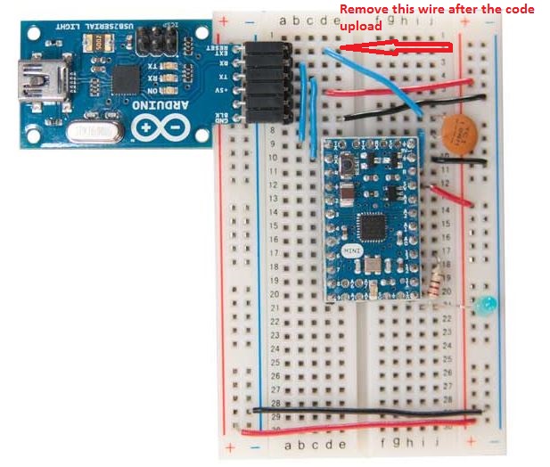
-
I have re-wired everything and it works now if I remove the wire from the USB Adapter "EXT. RESET" signal to the 100nF capacitor connected to the Arduino RESET pin - after the code upload.
I guess we can say "solved", I still can use the Arduino Mini if I remove either the RESET capacitor or the wire to this capacitor, like in the attached picture ... nice help on this forum anyway:-)
Hello! It looks like you're interested in this conversation, but you don't have an account yet.
Getting fed up of having to scroll through the same posts each visit? When you register for an account, you'll always come back to exactly where you were before, and choose to be notified of new replies (either via email, or push notification). You'll also be able to save bookmarks and upvote posts to show your appreciation to other community members.
With your input, this post could be even better 💗
Register Login