ds18b20 and negative temperature values
-
hi,
I'm having problems with negative temperatures on a node with 2 ds18b20
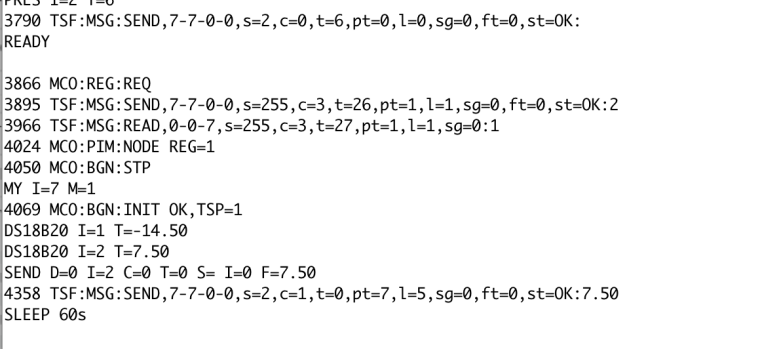
if both sensors measure the positive temperature, the values are correctly sent. If one of the 2 negative negative values is ignored.
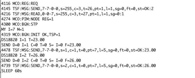
everything works correctly using the example in the library.both positive values

One Negative value

-
Config.h
#ifndef config_h
#define config_h

/**********************************
 * Sketch configuration
 */

#define SKETCH_NAME "Temperatura"
#define SKETCH_VERSION "1.0"

/**********************************
 * MySensors node configuration
 */

// General settings
#define MY_BAUD_RATE 9600
#define MY_DEBUG
//#define MY_NODE_ID 100
//#define MY_SMART_SLEEP_WAIT_DURATION_MS 500

// NRF24 radio settings
#define MY_RADIO_NRF24
//#define MY_RF24_ENABLE_ENCRYPTION
//#define MY_RF24_CHANNEL 76
//#define MY_RF24_PA_LEVEL RF24_PA_HIGH
//#define MY_DEBUG_VERBOSE_RF24
//#define MY_RF24_DATARATE RF24_250KBPS

// RFM69 radio settings
//#define MY_RADIO_RFM69
//#define MY_RFM69_FREQUENCY RF69_868MHZ
//#define MY_RFM69_FREQUENCY RFM69_868MHZ
//#define MY_IS_RFM69HW
//#define MY_RFM69_NEW_DRIVER
//#define MY_RFM69_ENABLE_ENCRYPTION
//#define MY_RFM69_NETWORKID 100
//#define MY_DEBUG_VERBOSE_RFM69
//#define MY_RF69_IRQ_PIN D1
//#define MY_RF69_IRQ_NUM MY_RF69_IRQ_PIN
//#define MY_RF69_SPI_CS D2
//#define MY_RFM69_ATC_MODE_DISABLED

// RS485 serial transport settings
//#define MY_RS485
//#define MY_RS485_BAUD_RATE 9600
//#define MY_RS485_DE_PIN 2
//#define MY_RS485_MAX_MESSAGE_LENGTH 40
//#define MY_RS485_HWSERIAL Serial1

// Message signing settings
//#define MY_SIGNING_SOFT
//#define MY_SIGNING_SOFT_RANDOMSEED_PIN 7
//#define MY_SIGNING_REQUEST_SIGNATURES
//#define MY_SIGNING_ATSHA204

// OTA Firmware update settings
//#define MY_OTA_FIRMWARE_FEATURE
//#define OTA_WAIT_PERIOD 300
//#define FIRMWARE_MAX_REQUESTS 2
//#define MY_OTA_RETRY 2

/**********************************
 * MySensors gateway configuration
 */
// Common gateway settings
//#define MY_REPEATER_FEATURE

// Serial gateway settings
//#define MY_GATEWAY_SERIAL

// Ethernet gateway settings
//#define MY_GATEWAY_W5100

// ESP8266 gateway settings
//#define MY_GATEWAY_ESP8266
//#define MY_ESP8266_SSID ""
//#define MY_ESP8266_PASSWORD ""

// Gateway networking settings
//#define MY_IP_ADDRESS 192,168,178,87
//#define MY_IP_GATEWAY_ADDRESS 192,168,178,1
//#define MY_IP_SUBNET_ADDRESS 255,255,255,0
//#define MY_PORT 5003
//#define MY_GATEWAY_MAX_CLIENTS 2
//#define MY_USE_UDP

// Gateway MQTT settings
//#define MY_GATEWAY_MQTT_CLIENT
//#define MY_CONTROLLER_IP_ADDRESS 192, 168, 178, 68
//#define MY_PORT 1883
//#define MY_MQTT_USER "username"
//#define MY_MQTT_PASSWORD "password"
//#define MY_MQTT_CLIENT_ID "mysensors-1"
//#define MY_MQTT_PUBLISH_TOPIC_PREFIX "mygateway1-out"
//#define MY_MQTT_SUBSCRIBE_TOPIC_PREFIX "mygateway1-in"

// Gateway inclusion mode
//#define MY_INCLUSION_MODE_FEATURE
//#define MY_INCLUSION_BUTTON_FEATURE
//#define MY_INCLUSION_MODE_DURATION 60
//#define MY_DEFAULT_LED_BLINK_PERIOD 300

// Gateway Leds settings
//#define MY_DEFAULT_ERR_LED_PIN 4
//#define MY_DEFAULT_RX_LED_PIN  5
//#define MY_DEFAULT_TX_LED_PIN  6

/***********************************
 * NodeManager configuration
 */

// if enabled, enable debug messages on serial port
#define DEBUG 1

// if enabled, enable the capability to power on sensors with the arduino's pins to save battery while sleeping
#define POWER_MANAGER 1
// if enabled, will load the battery manager library to allow the battery level to be reported automatically or on demand
#define BATTERY_MANAGER 1
// if enabled, allow modifying the configuration remotely by interacting with the configuration child id
#define REMOTE_CONFIGURATION 1
// if enabled, persist the remote configuration settings on EEPROM
#define PERSIST 0
// if enabled, a battery sensor will be created at BATTERY_CHILD_ID (201 by default) and will report vcc voltage together with the battery level percentage
#define BATTERY_SENSOR 1
// if enabled, a signal sensor will be created at RSSI_CHILD_ID (202 by default) and will report the signal quality of the transport layer
#define SIGNAL_SENSOR 0
// if enabled, send a SLEEPING and AWAKE service messages just before entering and just after leaving a sleep cycle and STARTED when starting/rebooting
#define SERVICE_MESSAGES 0

// Enable this module to use one of the following sensors: SENSOR_ANALOG_INPUT, SENSOR_LDR, SENSOR_THERMISTOR, SENSOR_ML8511, SENSOR_ACS712, SENSOR_RAIN, SENSOR_SOIL_MOISTURE
#define MODULE_ANALOG_INPUT 0
// Enable this module to use one of the following sensors: SENSOR_DIGITAL_INPUT
#define MODULE_DIGITAL_INPUT 0
// Enable this module to use one of the following sensors: SENSOR_DIGITAL_OUTPUT, SENSOR_RELAY, SENSOR_LATCHING_RELAY
#define MODULE_DIGITAL_OUTPUT 0
// Enable this module to use one of the following sensors: SENSOR_DHT11, SENSOR_DHT22
#define MODULE_DHT 0
// Enable this module to use one of the following sensors: SENSOR_SHT21, SENSOR_HTU21D
#define MODULE_SHT21 0
// Enable this module to use one of the following sensors: SENSOR_SWITCH, SENSOR_DOOR, SENSOR_MOTION
#define MODULE_SWITCH 0
// Enable this module to use one of the following sensors: SENSOR_DS18B20
#define MODULE_DS18B20 1
// Enable this module to use one of the following sensors: SENSOR_BH1750
#define MODULE_BH1750 0
// Enable this module to use one of the following sensors: SENSOR_MLX90614
#define MODULE_MLX90614 0
// Enable this module to use one of the following sensors: SENSOR_BME280
#define MODULE_BME280 0
// Enable this module to use one of the following sensors: SENSOR_SONOFF
#define MODULE_SONOFF 0
// Enable this module to use one of the following sensors: SENSOR_BMP085
#define MODULE_BMP085 0
// Enable this module to use one of the following sensors: SENSOR_HCSR04
#define MODULE_HCSR04 0
// Enable this module to use one of the following sensors: SENSOR_MCP9808
#define MODULE_MCP9808 0
// Enable this module to use one of the following sensors: SENSOR_MQ
#define MODULE_MQ 0
// Enable this module to use one of the following sensors: SENSOR_MHZ19
#define MODULE_MHZ19 0
// Enable this module to use one of the following sensors: SENSOR_AM2320
#define MODULE_AM2320 0
// Enable this module to use one of the following sensors: SENSOR_TSL2561
#define MODULE_TSL2561 0
// Enable this module to use one of the following sensors: SENSOR_PT100
#define MODULE_PT100 0
// Enable this module to use one of the following sensors: SENSOR_BMP280
#define MODULE_BMP280 0
// Enable this module to use one of the following sensors: SENSOR_DIMMER
#define MODULE_DIMMER 0
// Enable this module to use one of the following sensors: SENSOR_RAIN_GAUGE, SENSOR_POWER_METER, SENSOR_WATER_METER
#define MODULE_PULSE_METER 0

#endif
File
/* NodeManager is intended to take care on your behalf of all those common tasks a MySensors node has to accomplish, speeding up the development cycle of your projects. NodeManager includes the following main components: - Sleep manager: allows managing automatically the complexity behind battery-powered sensors spending most of their time sleeping - Power manager: allows powering on your sensors only while the node is awake - Battery manager: provides common functionalities to read and report the battery level - Remote configuration: allows configuring remotely the node without the need to have physical access to it - Built-in personalities: for the most common sensors, provide embedded code so to allow their configuration with a single line Documentation available on: https://github.com/mysensors/NodeManager */ // load user settings #include "config.h" // include supporting libraries #ifdef MY_GATEWAY_ESP8266 #include <ESP8266WiFi.h> #endif // load MySensors library #include <MySensors.h> // load NodeManager library #include "NodeManager.h" // create a NodeManager instance NodeManager nodeManager; // before void before() { // setup the serial port baud rate Serial.begin(MY_BAUD_RATE); nodeManager.registerSensor(SENSOR_DS18B20, 3); nodeManager.setBatteryMin(1.8); nodeManager.setBatteryMin(3.2); nodeManager.setSleepMinutes(1); /* Register below your sensors */ /* Register above your sensors */ nodeManager.before(); } // presentation void presentation() { // call NodeManager presentation routine nodeManager.presentation(); } // setup void setup() { // call NodeManager setup routine nodeManager.setup(); } // loop void loop() { // call NodeManager loop routine nodeManager.loop(); } // receive void receive(const MyMessage &message) { // call NodeManager receive routine nodeManager.receive(message); } // receiveTime void receiveTime(unsigned long ts) { // call NodeManager receiveTime routine nodeManager.receiveTime(ts); } -
I solved the problem.
The error is in the NodeManager.cpp file in the section below here calculates the average of the detected values.
Exactly at this point// process a float value else if (_value_type == TYPE_FLOAT && total > -1)the program does not send data if the average of the measurements is less than -1.
Certainly a lapse.
The average reading of a temperature sensor may also be negative.
Removed control> -1 and the negative reads sell sent.
It is necessary to analyze the behavior of the program when a sensor does not work, generating as -127 reading. I did not see if the library already does this check. -
Sorry for the delayed answer! Referencing https://github.com/mysensors/NodeManager/issues/219 to follow the resolution which as I mentioned might be a bit more complex unfortunately :)


