PIzeroW + RFM69HW + arduino node connection problem
Troubleshooting
14
Posts
4
Posters
3.1k
Views
3
Watching
-
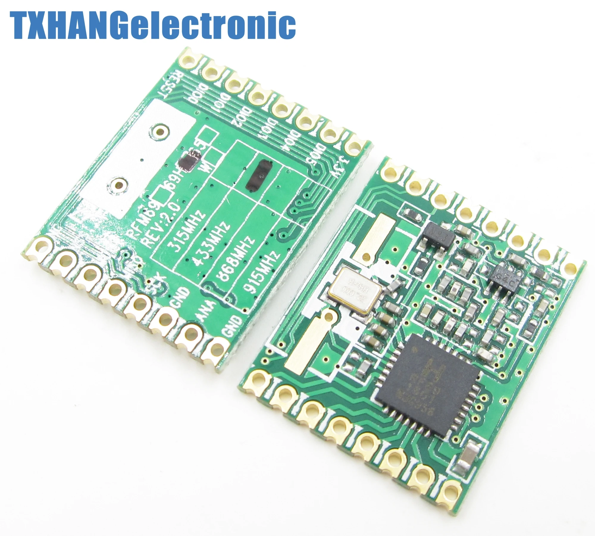
Are you sure the radios are hw and not w only? Make sure you have the irq pin connected on gateway and nodes.
-
The HW are the high power version, w are the standard. I'm asking because I got the w delivered instead of the hw and I lost so much time because the code wasn't working since I enabled the define for the hw version
-
An other update:
Did a radio test:
Test program (only difference is the node id):
// ***************************************************************************************
// Sample RFM69 sketch for Moteino to illustrate:
//   - sending
//   - receiving
//   - automatic transmission control
//   - button reading/interrupts
// ***************************************************************************************
// When you press the button on the SENDER Moteino, it will send a short message to the
// RECEIVER Moteino and wait for an ACK (acknowledgement that message was received) from
// the RECEIVER Moteino. If the ACK was received, the SENDER will blink the onboard LED
// a few times. The RECEIVER listens to a specific token, and it alternates the onboard LED
// state from HIGH to LOW or vice versa whenever this token is received.
// ***************************************************************************************
// Hardware setup:
// ***************************************************************************************
// On the sender, hook up a momentary tactile button to D3 like this:
//          __-__
//        __|   |___
// GND ----> BTN ----> D3 (D11 on MoteinoMEGA)
// Load this sketch on the RECEIVER with NODEID=RECEIVER (adjust in config section below)
// Load this sketch on the SENDER with NODEID=SENDER (adjust in config section below)
// RFM69 library and code by Felix Rusu - felix@lowpowerlab.com
// Get libraries at: https://github.com/LowPowerLab/
// Make sure you adjust the settings in the configuration section below !!!
// **********************************************************************************
// Copyright Felix Rusu 2016, http://www.LowPowerLab.com/contact
// **********************************************************************************
// License
// **********************************************************************************
// This program is free software; you can redistribute it
// and/or modify it under the terms of the GNU General
// Public License as published by the Free Software
// Foundation; either version 3 of the License, or
// (at your option) any later version.
//
// This program is distributed in the hope that it will
// be useful, but WITHOUT ANY WARRANTY; without even the
// implied warranty of MERCHANTABILITY or FITNESS FOR A
// PARTICULAR PURPOSE. See the GNU General Public
// License for more details.
//
// Licence can be viewed at
// http://www.gnu.org/licenses/gpl-3.0.txt
//
// Please maintain this license information along with authorship
// and copyright notices in any redistribution of this code
// **********************************************************************************
#include <RFM69.h>         //get it here: https://www.github.com/lowpowerlab/rfm69
#include <RFM69_ATC.h>     //get it here: https://github.com/lowpowerlab/RFM69
#include <SPI.h>           //included with Arduino IDE (www.arduino.cc)
#include <LowPower.h>      //get library from: https://github.com/lowpowerlab/lowpower

//****************************************************************************************************************
//**** IMPORTANT RADIO SETTINGS - YOU MUST CHANGE/CONFIGURE TO MATCH YOUR HARDWARE TRANSCEIVER CONFIGURATION! ****
//****************************************************************************************************************
#define NETWORKID     100  //the same on all nodes that talk to each other
#define RECEIVER      1    //unique ID of the gateway/receiver
#define SENDER        2
#define NODEID        SENDER  //change to "SENDER" if this is the sender node (the one with the button)
//Match frequency to the hardware version of the radio on your Moteino (uncomment one):
#define FREQUENCY     RF69_433MHZ
//#define FREQUENCY     RF69_868MHZ
//#define FREQUENCY     RF69_915MHZ
#define ENCRYPTKEY    "sampleEncryptKey" //exactly the same 16 characters/bytes on all nodes!
#define IS_RFM69HW_HCW  //uncomment only for RFM69HW/HCW! Leave out if you have RFM69W/CW!
//*****************************************************************************************************************************
#define ENABLE_ATC      //comment out this line to disable AUTO TRANSMISSION CONTROL
#define ATC_RSSI        -75
//*********************************************************************************************
#define SERIAL_BAUD   115200
#ifdef __AVR_ATmega1284P__
  #define LED           15 // Moteino MEGAs have LEDs on D15
  #define BUTTON_INT    1 //user button on interrupt 1 (D3)
  #define BUTTON_PIN    11 //user button on interrupt 1 (D3)
#else
  #define LED           13 // Moteinos have LEDs on D9
  #define BUTTON_INT    1 //user button on interrupt 1 (D3)
  #define BUTTON_PIN    3 //user button on interrupt 1 (D3)
#endif

#define LED_GREEN       4 //GREEN LED on the SENDER
#define LED_RED         5 //RED LED on the SENDER
#define RX_TOGGLE_PIN   7 //GPIO to toggle on the RECEIVER

#ifdef ENABLE_ATC
  RFM69_ATC radio;
#else
  RFM69 radio;
#endif

void setup() {
  Serial.begin(SERIAL_BAUD);
  radio.initialize(FREQUENCY,NODEID,NETWORKID);
#ifdef IS_RFM69HW_HCW
  radio.setHighPower(); //must include this only for RFM69HW/HCW!
#endif
  radio.encrypt(ENCRYPTKEY);

#ifdef ENABLE_ATC
  radio.enableAutoPower(ATC_RSSI);
#endif

  char buff[50];
  sprintf(buff, "\nListening at %d Mhz...", FREQUENCY==RF69_433MHZ ? 433 : FREQUENCY==RF69_868MHZ ? 868 : 915);
  Serial.println(buff);
  Serial.flush();
  pinMode(BUTTON_PIN, INPUT_PULLUP);
  pinMode(LED, OUTPUT);
  attachInterrupt(BUTTON_INT, handleButton, FALLING);

  pinMode(LED_GREEN, OUTPUT);
  pinMode(LED_RED, OUTPUT);
  pinMode(RX_TOGGLE_PIN, OUTPUT);
  digitalWrite(LED_GREEN, LOW);
  digitalWrite(LED_RED, HIGH);
}

//******** THIS IS INTERRUPT BASED DEBOUNCING FOR BUTTON ATTACHED TO D3 (INTERRUPT 1)
#define FLAG_INTERRUPT 0x01
volatile int mainEventFlags = 0;
boolean buttonPressed = false;
void handleButton()
{
  mainEventFlags |= FLAG_INTERRUPT;
}

byte LEDSTATE=LOW; //LOW=0
void loop() {
  //******** THIS IS INTERRUPT BASED DEBOUNCING FOR BUTTON ATTACHED TO D3 (INTERRUPT 1)
  if (mainEventFlags & FLAG_INTERRUPT)
  {
    LowPower.powerDown(SLEEP_120MS, ADC_OFF, BOD_ON);
    mainEventFlags &= ~FLAG_INTERRUPT;
    if (!digitalRead(BUTTON_PIN)) {
      buttonPressed=true;
    }
  }

  if (buttonPressed)
  {
    Serial.println("Button pressed!");
    buttonPressed = false;

    if(LEDSTATE==LOW)
    {
      LEDSTATE=HIGH;
      digitalWrite(LED_GREEN, HIGH);
      digitalWrite(LED_RED, LOW);
    }
    else
    {
      LEDSTATE=LOW;
      digitalWrite(LED_GREEN, LOW);
      digitalWrite(LED_RED, HIGH);
    }

    if (radio.sendWithRetry(RECEIVER, "Hi", 2)) //target node Id, message as string or byte array, message length
      Blink(LED, 40, 3); //blink LED 3 times, 40ms between blinks
  }

  //check if something was received (could be an interrupt from the radio)
  if (radio.receiveDone())
  {
    //print message received to serial
    Serial.print('[');Serial.print(radio.SENDERID);Serial.print("] ");
    Serial.print((char*)radio.DATA);
    Serial.print("   [RX_RSSI:");Serial.print(radio.RSSI);Serial.print("]");
    Serial.println();

    //check if received message is 2 bytes long, and check if the message is specifically "Hi"
    if (radio.DATALEN==2 && radio.DATA[0]=='H' && radio.DATA[1]=='i')
    {
      if(LEDSTATE==LOW)
        LEDSTATE=HIGH;
      else LEDSTATE=LOW;
      digitalWrite(LED, LEDSTATE);
      digitalWrite(RX_TOGGLE_PIN, LEDSTATE);
    }

    //check if sender wanted an ACK
    if (radio.ACKRequested())
    {
      radio.sendACK();
      Serial.print(" - ACK sent");
    }
  }

  radio.receiveDone(); //put radio in RX mode
  Serial.flush(); //make sure all serial data is clocked out before sleeping the MCU
  LowPower.powerDown(SLEEP_8S, ADC_OFF, BOD_ON); //sleep Moteino in low power mode (to save battery)
}

void Blink(byte PIN, byte DELAY_MS, byte loops)
{
  for (byte i=0; i<loops; i++)
  {
    digitalWrite(PIN,HIGH);
    delay(DELAY_MS);
    digitalWrite(PIN,LOW);
    delay(DELAY_MS);
  }
}
which results in:
Listening at 433 Mhz...
[2] Hi   [RX_RSSI:-56]
 - ACK sent[2] Hi   [RX_RSSI:-58]
 - ACK sent[2] Hi   [RX_RSSI:-58]
 - ACK sent[2] Hi   [RX_RSSI:-57]
 - ACK sent[2] Hi   [RX_RSSI:-57]
 - ACK sent[2] Hi   [RX_RSSI:-59]
 - ACK sent[2] Hi   [RX_RSSI:-59]
 - ACK sent[2] Hi   [RX_RSSI:-59]
 - ACK sent[2] Hi   [RX_RSSI:-59]
 - ACK sent[2] Hi   [RX_RSSI:-59]
 - ACK sent[2] Hi   [RX_RSSI:-60]
 - ACK sent[2] Hi   [RX_RSSI:-60]
 - ACK sent[2] Hi   [RX_RSSI:-61]
 - ACK sent[2] Hi   [RX_RSSI:-62]
 - ACK sent[2] Hi   [RX_RSSI:-62]
 - ACK sent[2] Hi   [RX_RSSI:-62]
 - ACK sent[2] Hi   [RX_RSSI:-63]
 - ACK sent[2] Hi   [RX_RSSI:-62]
 - ACK sent[2] Hi   [RX_RSSI:-64]
 - ACK sent[2] Hi   [RX_RSSI:-64]
 - ACK sent[2] Hi   [RX_RSSI:-65]
So my radio"s and arduino"s are fine.
Which brings me to the question is the Raspberry pi zero w not supported? Will try the RPI3 tomorrow.