Easy/Newbie PCB for MySensors


  • @korttoma yes i use the pro mini 3,3V but can Ireplace the Radios simply with a modification of the Sketch ? Because hen I Flash following Sketch to the Easy pcb:

    // Sample RFM69 receiver/gateway sketch, with ACK and optional encryption, and Automatic Transmission Control
    // Passes through any wireless received messages to the serial port & responds to ACKs
    // It also looks for an onboard FLASH chip, if present
    // **********************************************************************************
    // Copyright Felix Rusu 2016, http://www.LowPowerLab.com/contact
    // **********************************************************************************
    // License
    // **********************************************************************************
    // This program is free software; you can redistribute it 
    // and/or modify it under the terms of the GNU General    
    // Public License as published by the Free Software       
    // Foundation; either version 3 of the License, or        
    // (at your option) any later version.                    
    //                                                        
    // This program is distributed in the hope that it will   
    // be useful, but WITHOUT ANY WARRANTY; without even the  
    // implied warranty of MERCHANTABILITY or FITNESS FOR A   
    // PARTICULAR PURPOSE. See the GNU General Public        
    // License for more details.                              
    //                                                        
    // Licence can be viewed at                               
    // http://www.gnu.org/licenses/gpl-3.0.txt
    //
    // Please maintain this license information along with authorship
    // and copyright notices in any redistribution of this code
    // **********************************************************************************
    #include <RFM69.h>         //get it here: https://www.github.com/lowpowerlab/rfm69
    #include <RFM69_ATC.h>     //get it here: https://www.github.com/lowpowerlab/rfm69
    #include <SPIFlash.h>      //get it here: https://www.github.com/lowpowerlab/spiflash
    #include <SPI.h>           //included with Arduino IDE install (www.arduino.cc)
    
    //*********************************************************************************************
    //************ IMPORTANT SETTINGS - YOU MUST CHANGE/CONFIGURE TO FIT YOUR HARDWARE *************
    //*********************************************************************************************
    #define NODEID        1    //unique for each node on same network
    #define NETWORKID     100  //the same on all nodes that talk to each other
    //Match frequency to the hardware version of the radio on your Moteino (uncomment one):
    //#define FREQUENCY     RF69_433MHZ
    #define FREQUENCY     RF69_868MHZ
    //#define FREQUENCY     RF69_915MHZ
    #define ENCRYPTKEY    "sampleEncryptKey" //exactly the same 16 characters/bytes on all nodes!
    #define IS_RFM69HW_HCW  //uncomment only for RFM69HW/HCW! Leave out if you have RFM69W/CW!
    //*********************************************************************************************
    //Auto Transmission Control - dials down transmit power to save battery
    //Usually you do not need to always transmit at max output power
    //By reducing TX power even a little you save a significant amount of battery power
    //This setting enables this gateway to work with remote nodes that have ATC enabled to
    //dial their power down to only the required level
    #define ENABLE_ATC    //comment out this line to disable AUTO TRANSMISSION CONTROL
    //*********************************************************************************************
    #define SERIAL_BAUD   115200
    
    #ifdef __AVR_ATmega1284P__
      #define LED           15 // Moteino MEGAs have LEDs on D15
      #define FLASH_SS      23 // and FLASH SS on D23
    #else
      #define LED           9 // Moteinos have LEDs on D9
      #define FLASH_SS      8 // and FLASH SS on D8
    #endif
    
    #ifdef ENABLE_ATC
      RFM69_ATC radio;
    #else
      RFM69 radio;
    #endif
    
    SPIFlash flash(FLASH_SS, 0xEF30); //EF30 for 4mbit  Windbond chip (W25X40CL)
    bool promiscuousMode = false; //set to 'true' to sniff all packets on the same network
    
    void setup() {
      Serial.begin(SERIAL_BAUD);
      delay(10);
      radio.initialize(FREQUENCY,NODEID,NETWORKID);
    #ifdef IS_RFM69HW_HCW
      radio.setHighPower(); //must include this only for RFM69HW/HCW!
    #endif
      radio.encrypt(ENCRYPTKEY);
      radio.promiscuous(promiscuousMode);
      //radio.setFrequency(919000000); //set frequency to some custom frequency
      char buff[50];
      sprintf(buff, "\nListening at %d Mhz...", FREQUENCY==RF69_433MHZ ? 433 : FREQUENCY==RF69_868MHZ ? 868 : 915);
      Serial.println(buff);
      if (flash.initialize())
      {
        Serial.print("SPI Flash Init OK. Unique MAC = [");
        flash.readUniqueId();
        for (byte i=0;i<8;i++)
        {
          Serial.print(flash.UNIQUEID[i], HEX);
          if (i!=8) Serial.print(':');
        }
        Serial.println(']');
        
        //alternative way to read it:
        //byte* MAC = flash.readUniqueId();
        //for (byte i=0;i<8;i++)
        //{
        //  Serial.print(MAC[i], HEX);
        //  Serial.print(' ');
        //}
      }
      else
        Serial.println("SPI Flash MEM not found (is chip soldered?)...");
        
    #ifdef ENABLE_ATC
      Serial.println("RFM69_ATC Enabled (Auto Transmission Control)");
    #endif
    }
    
    byte ackCount=0;
    uint32_t packetCount = 0;
    void loop() {
      //process any serial input
      if (Serial.available() > 0)
      {
        char input = Serial.read();
        if (input == 'r') //d=dump all register values
          radio.readAllRegs();
        if (input == 'E') //E=enable encryption
          radio.encrypt(ENCRYPTKEY);
        if (input == 'e') //e=disable encryption
          radio.encrypt(null);
        if (input == 'p')
        {
          promiscuousMode = !promiscuousMode;
          radio.promiscuous(promiscuousMode);
          Serial.print("Promiscuous mode ");Serial.println(promiscuousMode ? "on" : "off");
        }
        
        if (input == 'd') //d=dump flash area
        {
          Serial.println("Flash content:");
          int counter = 0;
    
          while(counter<=256){
            Serial.print(flash.readByte(counter++), HEX);
            Serial.print('.');
          }
          while(flash.busy());
          Serial.println();
        }
        if (input == 'D')
        {
          Serial.print("Deleting Flash chip ... ");
          flash.chipErase();
          while(flash.busy());
          Serial.println("DONE");
        }
        if (input == 'i')
        {
          Serial.print("DeviceID: ");
          word jedecid = flash.readDeviceId();
          Serial.println(jedecid, HEX);
        }
        if (input == 't')
        {
          byte temperature =  radio.readTemperature(-1); // -1 = user cal factor, adjust for correct ambient
          byte fTemp = 1.8 * temperature + 32; // 9/5=1.8
          Serial.print( "Radio Temp is ");
          Serial.print(temperature);
          Serial.print("C, ");
          Serial.print(fTemp); //converting to F loses some resolution, obvious when C is on edge between 2 values (ie 26C=78F, 27C=80F)
          Serial.println('F');
        }
      }
    
      if (radio.receiveDone())
      {
        Serial.print("#[");
        Serial.print(++packetCount);
        Serial.print(']');
        Serial.print('[');Serial.print(radio.SENDERID, DEC);Serial.print("] ");
        if (promiscuousMode)
        {
          Serial.print("to [");Serial.print(radio.TARGETID, DEC);Serial.print("] ");
        }
        for (byte i = 0; i < radio.DATALEN; i++)
          Serial.print((char)radio.DATA[i]);
        Serial.print("   [RX_RSSI:");Serial.print(radio.RSSI);Serial.print("]");
        
        if (radio.ACKRequested())
        {
          byte theNodeID = radio.SENDERID;
          radio.sendACK();
          Serial.print(" - ACK sent.");
    
          // When a node requests an ACK, respond to the ACK
          // and also send a packet requesting an ACK (every 3rd one only)
          // This way both TX/RX NODE functions are tested on 1 end at the GATEWAY
          if (ackCount++%3==0)
          {
            Serial.print(" Pinging node ");
            Serial.print(theNodeID);
            Serial.print(" - ACK...");
            delay(3); //need this when sending right after reception .. ?
            if (radio.sendWithRetry(theNodeID, "ACK TEST", 8, 0))  // 0 = only 1 attempt, no retries
              Serial.print("ok!");
            else Serial.print("nothing");
          }
        }
        Serial.println();
        Blink(LED,3);
      }
    }
    
    void Blink(byte PIN, int DELAY_MS)
    {
      pinMode(PIN, OUTPUT);
      digitalWrite(PIN,HIGH);
      delay(DELAY_MS);
      digitalWrite(PIN,LOW);
    }


    I get following result:

    Listening at 868 Mhz...
    SPI Flash MEM not found (is chip soldered?)...
    RFM69_ATC Enabled (Auto Transmission Control)


  • Mod

    @Markus.

    I am using these and they work https://www.mysensors.org/hardware/nrf2rfm69


  • @gohan its eactly the adaptor board which i try to use at the Moment.
    But I am not sure If the test Sketch can work. Because the pin Definition could be different to get it working on the Easy PCB with RFM69 ?!


  • Mod

    No, I only changed the define from nrf24 to rfm69 and that was it. The capacitor I left the one on the EASYPCB near the nrf24 connector (a 10uF ceramic)


  • @gohan Sounds good 🙂 well, I have a 10uF electrolytic there. Hope it makes not the big difference. On the boards with NRF works that fine so far.


  • Mod

    I used the ceramic becuse I had a bunch of those 😄


  • MySensors Evangelist

    @sundberg84: Received the V9 boards and started to work with them. Converting my nodes into smaller ones 😉

    I want to use it with my 5v arduino. So need voltage regulator for the radio. I guess you are using LE33 if I read the thread correctly. I have LM1117 which seems to be a hassle to fix on the board with the 'rough bulky' legs. Suggestions or just buy LE33 😉


  • Mod

    if you have MCP1700 you can still fit those


  • @sincze When I first got my rev8 boards a long time ago I had the same issue. I did manage to bend the leads and solder some extensions on one to get it to work, but in the end it was just too much of a pain in the arse. I ended up buying L78L33ACZ regulators which work just fine, but the board was designed using the LE33. The LE33 is an LDO regulator where the L78L33 is not. The quiscent current of the L78L33 regulator, which is something I forgot to look at when I bought them, is 6mA where the LE33 maxes out at 3mA, which is much better when building battery operated nodes.


  • Hardware Contributor

    As mentioned above, it works but you need to watch for the right pins... you might have to be careful bending those pins but I think its managable... My suggestion though is to look for volt. regulators with the same pinout.


  • MySensors Evangelist

    @dbemowsk said in Easy/Newbie PCB for MySensors:

    LDO regulator

    A well that is a clear answer. So I just ordered a few LE33. The project has to wait.
    It still will be a tough one getting everyting attached to the pins. ->. 2x Door Sensor / 3x Dallas DS18B20 / 3x Relais / 2x Control LEDS TX/RX. A well part of the game. Already figured out I have to use the A0x pins as digital ones. As i don't plan to use IRQ I'm really hopeful this nicely designed PCB will offer me A0,A1A4,A5 D2,D3,D5,D6. So should fit 😉


  • @sincze With that much going on, you may want to connect a set of header pins to the outputs next to the nRF24 radio and run that to an external proto-board for connecting all of your devices. You won't make it on the small proto section of the newbie board for everything you want to add.


  • Hardware Contributor

    @dbemowsk @sincze - its a good idea with a proto board or you can build something and add as an shield on the MysX connector... I would also suggest you run a seperate power regulator for the sensors... atleast do some calculactions before adding them in because LE33 can handle maximum of 0.2A i think.


  • MySensors Evangelist

    @sundberg84 Ok tnx for the heads up. Currently I have everything in DEMO up and running on a NANO on my desk (using the exact same pins as I would on your PCB.
    I was thinking of the following. Power the PCB with 5v and use a 5v arduino mini, use the LE33 to power the Antenna with 3,3v. Hopefully this will enable the pins Mys pins A0 ...Dx with 5v.(Have to look at the schematic to be sure). Keeping your advise in mind to add some extra juice I have to power the RELAIS & Temp sensor separately with 5v and keep the grounds of everything together with the PCB. I think it should work. But maybe I am missing something.


  • Hardware Contributor

    @sincze all you can do is test and learn !!


  • @sundberg84 Couldn't think of the name of the MysX connector when I did that post, but that's what I was talking about putting the header on to connect to the proto-board. Mainly to act as a proto-shield. I would agree to run the sensors from a separate regulator. If he plugs it into the MysX connector he should have access to RAW power if he jumpers the pads next to the MysX connector, and then he may be able to make use of at least one of his LM1117 regulators on his shield, provided that he runs the sensors from 3.3V. I am assuming that his LM1117's are 3.3V regulators and not the 5V versions.


  • MySensors Evangelist

    @dbemowsk Got in stock 2 types of LM1117 the 3,3v and 5v. In any case the relais need 5v, the temp sensor as well. So If I read RAW in your answer that triggers me to watch out. 😉 I'll start soldering some pins and measure the voltage. as @sundberg84 said.. "all you can do is test and learn !! hehehe. Part of the Mysensors fun. And ofcourse this forum provides me with experienced feedback.


  • MySensors Evangelist

    So this is where the project is at. Using regulated 5V.
    Still missing the 0,1u capacitor, but it is on its way,
    0_1510686541052_PCB_001.jpg

    The voltage divider is working fine 5v -> 3,3v.
    Maybe I am missing some(connection)thing as I don't have 3,3v at the Antenna 3,3/GND connector. Did I miss something as I am not a PCB expert, sorry.


  • Hardware Contributor

    @sincze

    I don't have 3,3v at the Antenna 3,3/GND connector

    If you measure these points, what do you have?

    • plus (left pin) on blue screw terminal (should be 5v)
    • reg jumper (should be 5v)
    • Vin voltage reg (should be 5v)
    • Vout Voltage reg (should be 3.3v)

    You should be able to follow the trace from Vout to VCC(radio) with your eye.
    You can do a continuity test from Vout to VCC (radio) and GND(radio) to GND(screw terminal) to comfirm connectiom.

    What kind of voltage regulator do you have? Did you check the pinout matched vin/vout/gnd ?

    Still missing the 0,1u capacitor, but it is on its way,

    No rush, this supports the voltage reg but unless you do some heavy things you will do without.


  • MySensors Evangelist

    @sundberg84 I did measure the following:

    plus (left pin) on blue screw terminal (should be 5v), is 4,96 V
    Vin voltage reg (should be 5v), is 4,96
    Vout Voltage reg (should be 3.3v), is 3,3


  • Hardware Contributor

    @sincze but still 0v at radio VCC?


  • MySensors Evangelist

    @sundberg84 unfortunately yes. However.

    You can do a continuity test from Vout to VCC (radio) , (We have no beep for continuity)
    and
    GND(radio) to GND(screw terminal) to comfirm connectiom. (We have a beep for contiuity)


  • Hardware Contributor

    @sincze if this is so you have a broken pcb trace (first time I ever heard of) do you need to replace the trace with a wire.


  • Hardware Contributor

    @sincze or a bad solder joint...


  • MySensors Evangelist

    @sundberg84 as I am not a soldering king... we will check the work and report back...... applied a bit more solder to the vout and we have beep 😉 now let's continue the work.
    Wow, 3,3 and 3,29v on the antenna. tnx.


  • Hardware Contributor

    @sincze no worries. Good luck.


  • Hi,
    I‘m new to MySensors and the Newbie PCB. At the weekend I build my first sensor but I had one Problem. I want to use battery powered sensors so I’m using the 3.3V battery booster. I’m have connected/soltered everything and the Arduino was runing fine. But the NRF24-Module wasn’t working. I cheked it and there was no voltage at the Vcc pin of the NRF24. Then I found out, the NRF24 is only powered if the battery jumper is closed. If the battery jumper is opened there is not voltage at the NRF24 module and also not at the 3.3 pin of the MysX pin out. Ist this correct?I thought the NRF24 is powered by the battery booster by default. Or did I get it wrong?


  • Mod

    @SolderNewbie of course you need to close that jumper since you are using batteries.


  • MySensors Evangelist

    @sundberg84 tnx.
    I looked at the FAQ and could not find an explaination how to use the pins TX/RX.

    The following is now on my build list, but maybe if I can use TX/RX pins it will free something...

    1. LED RX=A05
    2. LED TX=D02
    3. Relay_1=A00
    4. Relay_2=A01
    5. Relay_3=A04
    6. Temp_D03 (total of 4, resistor currently already soldered into the wire)
    7. Door_Switch=D05
    8. Leakage_Switch=D06

    I tested the sketch on a Arduino Nano and it is working, now I need to convert everything to the Easy/Newbie PCB. 😉


  • @gohan
    But i want to power the NRF24 with the battery booster and not directly with the batteries. Is this possible? The NRF24 modules is working with 1.9V than i have to replace the batteries. But with the battery booster i can drain the batteries down to 0.4 V each!


  • Mod

    I think I did once a little mod for that case: I shorted Vin and Vout where the radio voltage regulator would be.

    PS but I shorted REG and not BAT


  • @gohan Thanks for this hint!
    I put a jumper into Vo and Vi of the voltage regulator pins and shorten it, that's all! Not needed to shorten REG or BAT jumper! The Vi pin is connected to the Vo of the battery booster and the Vo of the voltage regulator pin is connected to Vcc of the NRF24 module.

    Maybe an idea for rev 10? Battery booster powered NRF24 module?


  • Hardware Contributor

    @SolderNewbie

    If the battery jumper is opened there is not voltage at the NRF24 module and also not at the 3.3 pin of the MysX pin out. Ist this correct?I thought the NRF24 is powered by the battery booster by default. Or did I get it wrong?

    This is correct because you dont want to feed 3.3v from the booster to the radio. The radio is very sensitive to noise (which will be the case with the booster) and since the radio can handle down to 1.9v the pcb is used like the description How?>Battery 3.3v @ https://www.openhardware.io/view/4/EasyNewbie-PCB-for-MySensors. This will feed the vattery voltage only (not from Booster) and therefore not give noise to the radio.

    As mentioned above by @gohan its possible but not recommended... unless you got some really good modules you will end up with a 2m range on your radio (or no connection at all)

    Maybe an idea for rev 10? Battery booster powered NRF24 module?

    This is why Rev 1 and 2 never made it... I have been trying this out since 2014 and it just doesnt work. You might get lucky with 1 or 2 modules that works (or pay alot for low noise boosters which isnt my thought with EasyPCB).

    I would instead suggest lowering BOD and/or change bootloader.


  • Hardware Contributor

    @sincze

    use the pins TX/RX

    what do you mean? You can find the pins on the MysX connector (bottom left on the PCB). Instructions on how to use the pins isnt my cup of tea. You need to google that or you have to look at the arduino homepage.

    There isnt anything to convert from nano to EasyPCB (except to find the right pins). The sketch will work just fine as it is.


  • Mod

    @sundberg84 my cheap alixpress booster and CDEbyte NRF24 worked fine on my solar powered outdoor sensor


  • Hardware Contributor

    @gohan as I said, I have been doing EasyPCB since 2014 and you might get lucky 😉

    You need a great booster and a great radio - this works, but as we all know this combination when shopping from china is pure luck.


  • Mod

    I had to do it because the supercap can go to lower than 1.9V, but I noticed it wasn't that bad, probably because I was generous on ceramic caps 😀


  • Hardware Contributor

    @gohan - trust me, I have tried all the caps there are on the booster. I also have now recently checked with a oscilloscope but I cant see any major difference (in less noise vs with or without 0,1-10uF cap). I must admit I have more test to do in booster - EasyPCB (cap) so any input is appreciated but im not sure a bigger cap equals less noise. A smaller cap can react quicker than a big one i think and with that it means you have to find a balance with response - capacity. If so, I can see with the booster I have (bad quality) varies a lot on noise, and with that means you should need a different cap on every booster (depending on the noise).


  • Mod

    I have a 10uF ceramic on both booster output and near nrf24 socket and it has been working well. For battery powered nodes I'm moving to LiFePo4 batteries that have no need for booster and voltage divider. Much less hassle.


  • Hardware Contributor

    @gohan - yea, just as I said above. Moving to another battery or lower BOD/change bootloader is one good way to avoid booster problems. Good to hear its working well for you - lets hope it continues that way.


  • @sundberg84 Thanks for clarification! Do you have any idea how long i can power a NRF24 module with two AA batteries until the voltage is to low?


  • Hardware Contributor

    @SolderNewbie - it depends on many factors, but one example I have 2xAA, Pro Mini (Led and Voltage reg removed), DHT22, Voltage divider (for battery measurment), booster and sending temp & humidity + battery status every 15min should last 1-1.5 years.


  • MySensors Evangelist

    @sundberg84 Got it. In the end it I did not have to use them.

    All devices I was looking for to use are working except for my Dallas Temp Sensors.
    The resistor is between the wires VCC and DATA in the connectors so not soldered on the board itself.

    I checked if pin header
    D3 had connection with D3 on the arduino (beep),
    GND with GND on the arduino (beep),
    VCC with VCC on the arduino (beep) at 4,7v.

    So the connector should be okay (no soldering error this time). If I connect the wire to the old Arduino nano the temp sensors are found... Connect them to the PCB.. Nothing found. Well must be something stupid I am missing here right?.

    To check D3, I made an RX tranmission Led attached and it flashed fine. So it should be okay.


  • Hardware Contributor

    @sincze - that sounds strange.
    Is it the same sensor or could the dallas sensor be broken?
    Can you see anything in the debug/serial? /(Sometimes you can see -127 and so).


  • MySensors Evangelist

    @sundberg84 Strange thing is.. If I unplug the temp cable from the PCB and plug it into the NANO the sketch detects the sensor. The exact same sketch on the mini says "0 sensors found" as I just print the number of sensors detected.
    For debugging purposes If I would solder the resistor on the PCB and I have a different temp sensor with resistor within the cabling. Would that hurt (double resistors) ?
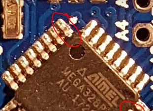
    Would I have to look for a specific voltage between D3 and GND ?


  • Hardware Contributor

    @sincze - so it sounds like you have issues between pcb connector and A0 pin on the atmega328. You could try to do a continuitytest between that - and check soldering job on the MysX connector and on the back on the pro mini (A0)

    0_1510823476205_upload-31f0d5a6-9fc8-42a1-bf58-2a6d7f490457


  • MySensors Evangelist

    @sundberg84 Just for the check A0 or D3 (temp sensor)?
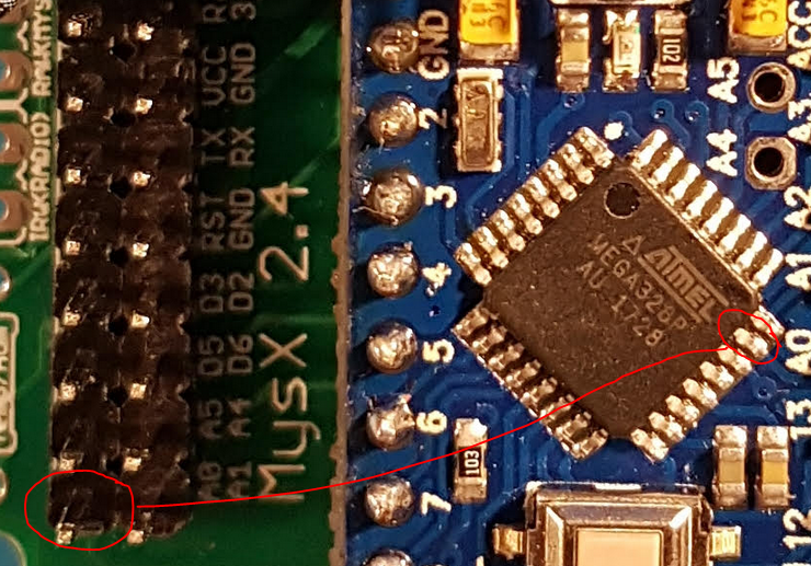
    As A0 is working, I have a relais attached to it. 😉


  • Hardware Contributor

    @sincze sorry - my misstake, D3 offcourse. You can do if from D3 on the MysX connector to D3 on the atmega chip. D3 on the cjip is the upper left pin on the image.

    0_1510831452813_upload-0d859cac-e93c-40ad-9f2f-f68ddcd6fdeb


  • MySensors Evangelist

    @sundberg84 yes, I have a 'beep' pffffff would a double resistor hurt ?? 1 on pcb the other one in the cable?
    I tried connecting it directly to pin 3 on the arduino, no detection, I tried replacing the resistor. nothing. I tried a different temp sensors.. No detection. I moved the new temp sensor to the nano... detected.
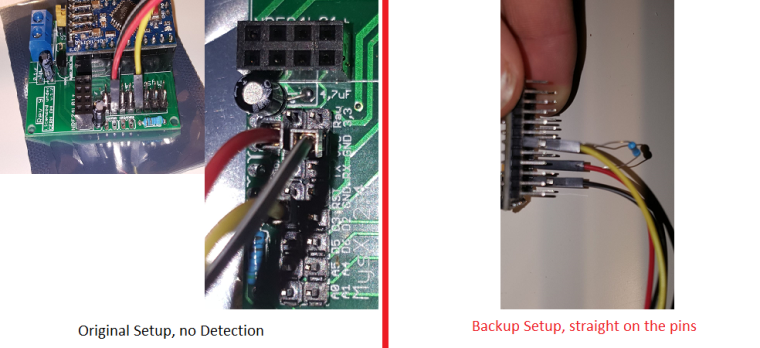
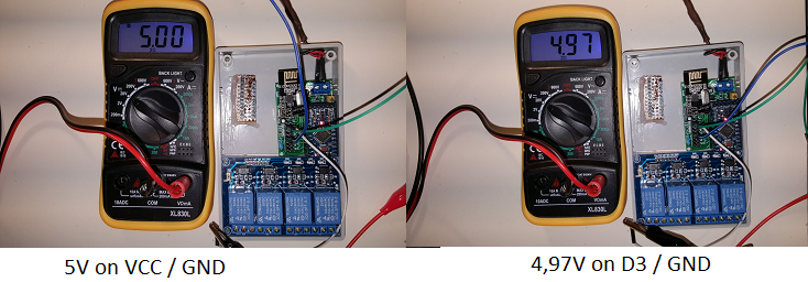
    I tried an empty Dallas temp only sketch on the mini... no detection. Well Now I'm lost 😉


  • @sincze Can you possibly send pictures with how you have it connected both on the nano and on the mini? I am thinking that it is something obvious that is being missed.


  • Hardware Contributor

    @sincze - and you use the right power source on the PCB? (VCC = 5v and 3.3v = Well... 3.3v) Please send pictures of both setup as mentioned.


  • Hi Sundberg84,

    I have some v8 and now enough time for playing.
    I setup with v3.3 2xAA, booster, NRF24, simple door sensor or DHT.
    1-2 week and the batteries are discharged, I hear little buzz from the mini or other components.
    This is the 2nd built where I meet this problem.
    Do you have any idea what component is the failed ?
    thanks
    Barna


  • Mod

    Did you remove the regulator and LED from the pro mini? Have you tried a different booster?


  • Hardware Contributor

    @Barna as @gohan said I suspect the booster as well. A small buzz is normally from that hardware.
    Also did you implement sleep() ?


  • @sundberg84 this is not normal buzz, stronger than before.
    I have used this source only: https://www.ebay.com/itm/mini-DC-DC-0-8-3-3V-to-DC-3-3V-Step-UP-Boost-Power-Module-For-Breadboard-Arduino-/281556288481?hash=item418e1003e1
    which another part could make the buzz ?
    yes, I use sleep
    sleep(1, CHANGE, SLEEP_TIME); SLEEP_TIME is 900000 , but the node does not wake up and send the battery status, only when door sensor changes.
    No, I have not removed the led and regulator, this is the testing period only 🙂


  • Mod

    Those draw quite some energy, you'd better remove them and see from there


  • @Barna What if you used a setup like this:
    0_1510936047717_upload-c0db2caa-660d-4a18-a9a9-c9c2cf96935c
    The 3volt tap can be used to power the arduino, and the DHT can be run from the 4.5v. With that you wouldn't need the step up booster.


  • MySensors Evangelist

    @sundberg84 @dbemowsk Thank you guys for still trying to help me. I almost gave up on using a Dallas Termp sensor o n a pro mini. As said I even tried connecting the temp sensor directly to the pins with same results. If I connect the pins to my nano, it is being detected and transmitting temp values. I even used a different sketch.. Just for the temp sensor. link found_here. Changed it to use Pin 3 ofcourse. I even connected the whole thing to D2 (resistor back in the wires)... without being succesful either.

    0_1510938558966_Dallas Not Detected.png


  • @sincze Are you sure you sure you got correct power on the GND and VCC pins on the MySX connector?


  • MySensors Evangelist

    @dbemowsk I had those thoughts as well.
    0_1510946155798_Dallas Voltage.png
    The voltage should be okay. I can solder a new Arduino Pro Mini and see if that one wants to work with me 😉


  • Hardware Contributor

    Dallas temp sensors needs 3.3v VCC if I remember right. Not 5v.


  • MySensors Evangelist

    @sundberg84 haha yes i was wondering that myself so tried it connecting it to 3,3v as well. However on the 5v nano working just fine. Technical specs tell me: Power supply range is 3.0V to 5.5V
    also mysensors link
    Pretty strange huh.


  • Hardware Contributor

    @sincze my mistake. Really strange this... Should work just fine. Can you upload a better resolution picture of your hardware and the sketch you are using?


  • @sincze I have 10 of these DS18B20s strung over approximately 12m monitoring all rooms on both floors of my house and two side lofts, all running on 3.22v from a Pro-Mini. Never have skipped a beat, reporting every 5 minutes, well, aside from a telephone socket which pins went walkabout (the chips are crimped to RJ11s).
    There is something not right with the physical arrangement if you can get the same circuit to report at 5v...


  • MySensors Evangelist

    @sundberg84 I just soldered a myself a new out of the box pro mini using the same sketch..

    10246 TSF:MSG:SEND,8-8-25-0,s=0,c=1,t=0,pt=7,l=5,sg=0,ft=4,st=OK:21.0
    250560 TSF:MSG:SEND,8-8-25-0,s=0,c=1,t=0,pt=7,l=5,sg=0,ft=0,st=OK:21.1
    255019 TSF:MSG:SEND,8-8-25-0,s=0,c=1,t=0,pt=7,l=5,sg=0,ft=0,st=OK:22.3
    259476 TSF:MSG:SEND,8-8-25-0,s=0,c=1,t=0,pt=7,l=5,sg=0,ft=0,st=OK:23.8
    263934 TSF:MSG:SEND,8-8-25-0,s=0,c=1,t=0,pt=7,l=5,sg=0,ft=0,st=OK:25.3
    268393 TSF:MSG:SEND,8-8-25-0,s=0,c=1,t=0,pt=7,l=5,sg=0,ft=0,st=OK:26.5
    272851 TSF:MSG:SEND,8-8-25-0,s=0,c=1,t=0,pt=7,l=5,sg=0,ft=0,st=OK:27.6
    277310 TSF:MSG:SEND,8-8-25-0,s=0,c=1,t=0,pt=7,l=5,sg=0,ft=0,st=OK:28.1
    281768 TSF:MSG:SEND,8-8-25-0,s=0,c=1,t=0,pt=7,l=5,sg=0,ft=0,st=OK:28.4
    290677 TSF:MSG:SEND,8-8-25-0,s=0,c=1,t=0,pt=7,l=5,sg=0,ft=0,st=OK:28.3
    295136 TSF:MSG:SEND,8-8-25-0,s=0,c=1,t=0,pt=7,l=5,sg=0,ft=0,st=OK:28.1
    299594 TSF:MSG:SEND,8-8-25-0,s=0,c=1,t=0,pt=7,l=5,sg=0,ft=0,st=OK:27.8
    304053 TSF:MSG:SEND,8-8-25-0,s=0,c=1,t=0,pt=7,l=5,sg=0,ft=0,st=OK:27.6
    308511 TSF:MSG:SEND,8-8-25-0,s=0,c=1,t=0,pt=7,l=5,sg=0,ft=0,st=OK:27.3
    312970 TSF:MSG:SEND,8-8-25-0,s=0,c=1,t=0,pt=7,l=5,sg=0,ft=0,st=OK:27.1
    317428 TSF:MSG:SEND,8-8-25-0,s=0,c=1,t=0,pt=7,l=5,sg=0,ft=0,st=OK:26.8
    321887 TSF:MSG:SEND,8-8-25-0,s=0,c=1,t=0,pt=7,l=5,sg=0,ft=0,st=OK:26.6
    326345 TSF:MSG:SEND,8-8-25-0,s=0,c=1,t=0,pt=7,l=5,sg=0,ft=0,st=OK:26.4

    Victory... 🙂


  • Mod

    Was the pro mini defective or just the pin you were using?


  • MySensors Evangelist

    @gohan Don't know. Pin3 could be used to drive the led tx without problems. It only did not work with the temp sensors. I moved the temp sensor to d2.... modified the sketch and it did not work as well. and d2 was driveing rx led. So well root cause unknown... solution: solder a new pro mini and keep the other one for different purpose.


  • @sincze Did you use D2+D3 on all the same devices?


  • Mod

    I'd try the other digital pins too


  • MySensors Evangelist

    @zboblamont @gohan The Sensor with the replaced Pro Mini is in production now ;-). I'll start soldering a new Easy/Newbie PCB, because once you know how to do it... it is Easy and test the individual pins with a door/window sensor.


  • Hi Sundberg84,
    What could you advise for battery powering (remove led and regulator too) if I would like to use Mini 5V and measure the battery level too ?
    thx

    Barna


  • Hardware Contributor

    @Barna the 5v pro mini are running a 16mhz crystal as default and this needs higher voltage to be stable compred to 8mhz (3.3v pro mini).

    I have never tried this so can't give much advice but I would probably take the effort of reprogramming the fuses and bootloader to a internal 1mhz and run the hardware as that (the hardware is the same on 5v except the regulator and crystal )


  • Mod

    @Barna why do you want to use a 5v arduino?


  • Hi Sundberg84,
    I have used this step up booster
    https://www.ebay.com/itm/181612513907?rmvSB=true

    but found this (2nd),
    https://www.ebay.com/itm/10Pcs-Mini-2-in-1-1-8V-5V-to-3-3V-DC-Step-Down-Step-Up-Converter-Power-For-Ardu/182793323053?hash=item2a8f54c22d:g:PJMAAOSwYL9ZzAXC
    It has lower noise, so I could connect the radio to the Mini. What do you think ?


  • Hardware Contributor

    @barna lower noice is better but I can not confirm this module is better. You have to try. Yes you can connect this to EasyPCB just like the first one.


  • Hi All!

    Could someone suggest me an elegant way to extend the mysx connector? SO i would like to multiple the A4 A5 pins onto another prototype board to use more I2C devices....


  • Hardware Contributor

    @tommas just add a wire on the back side to the prototyping area ? You could design a MysX daughter board as well 😉


  • @sundberg84

    Unofrtunately i havent got the skills and free time for a daughter board.:(. But doesnt have someone else a daughterboard?:)


  • @sundberg84

    Or have you got any suggestion expansion board for arduino mini pro ? Something like this: arduino-pro-mini-undershield (but it can not buy on ebay)


  • Hardware Contributor

    @tommas how about a wire to the prototyping area ?


  • @tommas you could easily take a piece of prototyping PCB like this and create your own daughter/prototyping board if you need more space than the prototyping area has.
    0_1512845129504_6f4f47c7-736c-4804-84f2-72b392d1e4fe-image.png
    Use a set of connectors like this to connect to the MysX connector on the easy newbie board.
    0_1512845514755_20e6995e-fad7-4318-93c3-98f5f0308046-image.png


  • Hardware Contributor

    I have plans for MYSX connector daughter boards, maybe if you tell me more about what you are planning to use I can adapt.


  • Hi community!
    i just got to fiddle around with my new newbie pcb and i ran into some problems.
    I am already quite familiar with mysensors as i have built quite a couple of different nodes which are working very well (all on bread boards or selfmade pcb boards)
    No i wanted to step up a bit and bought the newbie pcb boards.
    I want to have a battery powered setup. So i did solder all the parts on the board. checked my wiring many times and also checked all components. I even did check the whole pcb board if every line is ok with a multimeter.

    So my problem is:
    all the time i debug my node (mockup sketch) with the Arduino IDE powered by battery, stable power source etc i end up having the error TSP failed.

    when i leave my set up as is (i solders headers to the board to conveniently change the components ) and only power the NRF24 seperatly i get no errors. So it must be something with my power ?
    but i don't get it where exactly my problem lies.
    Could somebody help me?


  • Hardware Contributor

    @helvetian - hi, sure we can help!
    But it would be much easier if you described your hardware setup (picture?) and logs.
    The EasyPCB is versatile so you can use it in many ways, but a wrong combination can make it not work.
    Do you use a DC-DC booster? Batteries? Which jumpters did you solder? And so on...

    Did you by any chance connect both batteries and ftdi Vcc at the same time?


  • thx for your fast reply. i'm in the train right now. so i can't provide you now with any pics. as soon as possible i will do that!

    I am using a battery booster (as it seems the same as you use), i have the battery jumpers connected, all the resistors and caps for the battery measurement.
    It is just wired that it functions while the nrf24 is powered separately. maybe i got some bad radios?
    One more question: the cap just below the booster. is this necessary to reduce the noice for the radio? might that help and if yes what size do you recommend? i didn't solder any cap yet there.

    "Did you by any chance connect both batteries and ftdi Vcc at the same time?"
    Yes! I did try this as well. Same results...
    I should also mention i got my Arduino Pro mini battery powered hacked. So no more LED and Voltage regulator. But then again i also tried it with a untouched one.


  • Mod

    I am using 2 10uF ceramic caps both on booster and radio side, so I strongly recommend to get a bunch of those as they are working better than the electrolics and can be used in many ways.


  • Hardware Contributor

    @helvetian - good, sounds like a good start.
    If you have a booster + battery jumper in place this powers the radio separately. The most critical capacitor is the one close to VCC/GND on the Nrf24 radio. What value do you use here? Sometimes it helps to try higher values. I use 4,7 in normal cases but sometimes I either replace it or add in parallel a 47uF as well.

    maybe i got some bad radios?

    This is not uncommon... noice from the booster (also common) combined with a bad radio might do this.

    One more question: the cap just below the booster. is this necessary to reduce the noice for the radio?

    Yes and No - I dont have any hard evidence (there are caps on the booster itself) but I have had good results with a 0,1 cheramic cap for a node that didnt work. It doesnt hurt to add.

    "Did you by any chance connect both batteries and ftdi Vcc at the same time?"
    Yes! I did try this as well. Same results...

    Dont do this - only 1 Vcc allowed 🙂

    When you have the time, upload a picture - it will probably help us more to help you.


  • here are some pics form my pcb board!

    0_1516654067507_20180122_213519.jpg 0_1516654074837_20180122_213527.jpg 0_1516654086429_20180122_213538.jpg


  • Hardware Contributor

    @helvetian looks good! Nice work.
    I would start by soldering in/change capacitor on the radio and booster as mentioned. Try some other radio of you have. I have never connected the jumper for irq so just to test of nothing else works you can de-solder the irq jumper.


  • ok. thanks for the tips and your promt assistance! such a great community!
    i will try to experiment with some caps.
    i tested already a couple of different radios. but maybe i will get once a decent one which will work


  • Mod


  • @gohan
    just bought them on ali. What would you recommend in the meantime till they arrive here in snowy switzerland? i got a assortement of electrolyt caps.
    i got a bunch of 0.1uf ceramics. could i just solder(or test it on a breadboard) 10 of them to try out?


  • Mod

    try adding first one on the booster and see what happens


  • just a quick update.

    i ran some more tests with different radios and a 10uf electroltyte cap on the booster. And some different batteries.
    Heureka! It works. For now. It is running now with a 3.7v lipo battery without the voltage regulator. Does anybody know if this is safe in the long run?


  • Mod

    I wouldn't do it if I were you. You are going to fry the radio


  • Hardware Contributor

    If you bypassed the booster and that works it seems like you have a booster which generates alot of noice. Try bypassing it with 2xaa and see what happens.


  • @sundberg84 do you experience the same thing when you are using boosters? Some are better than other even tough they are the same model? Same with the radios?


  • Hardware Contributor

    @helvetian correct. I can buy a batch with 10 boosters and some works and some don't. Most can work with the right capacitors as support but a few was just impossible.


  • Mod

    @helvetian when dealing with cheap Chinese stuff, you always have to consider that you may have got a poor quality product and because of this I also bought LiFePo4 batteries that run at 3.3v so no regulator needed making it easy to figure out if it is a power issue or else


  • Thanks for clarifications

    Awesome forum!


Log in to reply
 

Suggested Topics

19
Online

11.2k
Users

11.1k
Topics

112.5k
Posts