Easy/Newbie PCB for MySensors
-
thx for your fast reply. i'm in the train right now. so i can't provide you now with any pics. as soon as possible i will do that!
I am using a battery booster (as it seems the same as you use), i have the battery jumpers connected, all the resistors and caps for the battery measurement.
It is just wired that it functions while the nrf24 is powered separately. maybe i got some bad radios?
One more question: the cap just below the booster. is this necessary to reduce the noice for the radio? might that help and if yes what size do you recommend? i didn't solder any cap yet there."Did you by any chance connect both batteries and ftdi Vcc at the same time?"
Yes! I did try this as well. Same results...
I should also mention i got my Arduino Pro mini battery powered hacked. So no more LED and Voltage regulator. But then again i also tried it with a untouched one.@helvetian - good, sounds like a good start.
If you have a booster + battery jumper in place this powers the radio separately. The most critical capacitor is the one close to VCC/GND on the Nrf24 radio. What value do you use here? Sometimes it helps to try higher values. I use 4,7 in normal cases but sometimes I either replace it or add in parallel a 47uF as well.maybe i got some bad radios?
This is not uncommon... noice from the booster (also common) combined with a bad radio might do this.
One more question: the cap just below the booster. is this necessary to reduce the noice for the radio?
Yes and No - I dont have any hard evidence (there are caps on the booster itself) but I have had good results with a 0,1 cheramic cap for a node that didnt work. It doesnt hurt to add.
"Did you by any chance connect both batteries and ftdi Vcc at the same time?"
Yes! I did try this as well. Same results...Dont do this - only 1 Vcc allowed :)
When you have the time, upload a picture - it will probably help us more to help you.
-
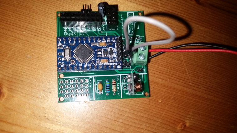
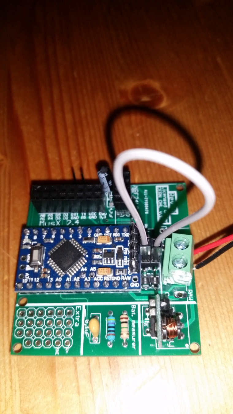
@helvetian looks good! Nice work.
I would start by soldering in/change capacitor on the radio and booster as mentioned. Try some other radio of you have. I have never connected the jumper for irq so just to test of nothing else works you can de-solder the irq jumper. -
ok. thanks for the tips and your promt assistance! such a great community!
i will try to experiment with some caps.
i tested already a couple of different radios. but maybe i will get once a decent one which will work -
get some of these, I am very happy I got them
https://www.aliexpress.com/item/Free-shipping-100PCS-Multilayer-ceramic-capacitor-10UF-106-50V-P-5-08mm/32783039097.html@gohan
just bought them on ali. What would you recommend in the meantime till they arrive here in snowy switzerland? i got a assortement of electrolyt caps.
i got a bunch of 0.1uf ceramics. could i just solder(or test it on a breadboard) 10 of them to try out? -
just a quick update.
i ran some more tests with different radios and a 10uf electroltyte cap on the booster. And some different batteries.
Heureka! It works. For now. It is running now with a 3.7v lipo battery without the voltage regulator. Does anybody know if this is safe in the long run? -
If you bypassed the booster and that works it seems like you have a booster which generates alot of noice. Try bypassing it with 2xaa and see what happens.
-
If you bypassed the booster and that works it seems like you have a booster which generates alot of noice. Try bypassing it with 2xaa and see what happens.
@sundberg84 do you experience the same thing when you are using boosters? Some are better than other even tough they are the same model? Same with the radios?
-
@sundberg84 do you experience the same thing when you are using boosters? Some are better than other even tough they are the same model? Same with the radios?
@helvetian correct. I can buy a batch with 10 boosters and some works and some don't. Most can work with the right capacitors as support but a few was just impossible.
-
@sundberg84 do you experience the same thing when you are using boosters? Some are better than other even tough they are the same model? Same with the radios?
@helvetian when dealing with cheap Chinese stuff, you always have to consider that you may have got a poor quality product and because of this I also bought LiFePo4 batteries that run at 3.3v so no regulator needed making it easy to figure out if it is a power issue or else
-
@helvetian - just so you dont miss this. A Atmega328 (Pro mini if you are using EasyPCB) can be run without a booster by reprogramming the fuses/bootloader. This is more advanced but possible. Then you can run the pro mini with a 8mhz or 1mhz internal clock down to the radio minimum 1.9v. This is a better option compared to boosters but harder to achieve.
@sundberg84 said in Easy/Newbie PCB for MySensors:
@helvetian - just so you dont miss this. A Atmega328 (Pro mini if you are using EasyPCB) can be run without a booster by reprogramming the fuses/bootloader. This is more advanced but possible. Then you can run the pro mini with a 8mhz or 1mhz internal clock down to the radio minimum 1.9v. This is a better option compared to boosters but harder to achieve.
No it is not "hard". You just need to copy files in a directory, edit a text file and flash ISP sketch on a nano or uno bard. Easier than dealing with unreliable boosters :p
-
@sundberg84 said in Easy/Newbie PCB for MySensors:
@helvetian - just so you dont miss this. A Atmega328 (Pro mini if you are using EasyPCB) can be run without a booster by reprogramming the fuses/bootloader. This is more advanced but possible. Then you can run the pro mini with a 8mhz or 1mhz internal clock down to the radio minimum 1.9v. This is a better option compared to boosters but harder to achieve.
No it is not "hard". You just need to copy files in a directory, edit a text file and flash ISP sketch on a nano or uno bard. Easier than dealing with unreliable boosters :p
@nca78 ... can be discussed. Wiring needs to be right. It's not hard when you know what to do but it's harder compared to a working booster.
Controller: Proxmox VM - Home Assistant
MySensors GW: Arduino Uno - W5100 Ethernet, Gw Shield Nrf24l01+ 2,4Ghz
MySensors GW: Arduino Uno - Gw Shield RFM69, 433mhz
RFLink GW - Arduino Mega + RFLink Shield, 433mhz -
@nca78 ... can be discussed. Wiring needs to be right. It's not hard when you know what to do but it's harder compared to a working booster.
-
@gohan - sorry, didnt understand?
-
I've just built a few nodes using the EasyPCB Rev 9 RFM69 Edition and I can confirm it lives up to its name - build takes only 15-20 mins, and node works first time because there is no chance of incorrectly wiring the radio. Thanks @sundberg84!
The PCB fits nicely along with 1 or 2 AA batteries into the 100x60x25 project boxes available on eBay for about $1 each:
(AA battery holder is actually about 1.5mm too long to fit - I've cut off the non-spring end of the holder, and the positive wire is held by tension between the +ve battery terminal and the side of the case. Ugly, but fine for nodes that don't get moved around. White tape is to prevent antenna from shorting against the top of the radio module.)
I have a couple of observations that might be worth considering to make the next revision even better:
- According to the MySX specification, MySX header pin 10 should be connected to Arduino pin D4, not D2 (which is already used for the radio)?
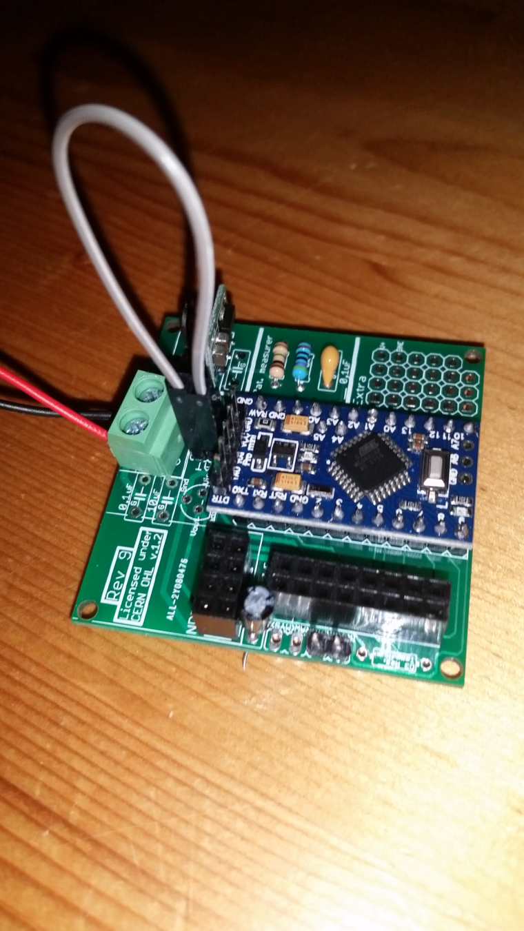
- It would be handy to have a bit more space between the voltage booster and the adjacent cap - boosters with pre-soldered right-angle headers don't fit without hiting the adjacent cap (see photo). You could free up some space for this by mounting the battery measurement resistors vertically. (There is a risk that this might cause the voltage divider circuit to pick up noise from the adjacent booster; which might cause a bit of random fluctuation in the battery voltage readings. I suppose you'd need to do some tests to see if this is actually an issue.)
- I put a few layers of insulating tape under the RFM69 so that it sits about 0.5mm clear of the PCB, to make it easier to desolder if the need ever arises (see photo). It would be nice if there were holes in the RFM69 pads so that it could optionally be mounted via 2mm male/female headers. You'd need to make a small adjustment to the antenna length if actually using headers, but otherwise I don't think this would affect the radio's performance.
- EDIT: You can surface-solder 2mm headers to the existing pads, but it ain't pretty:
- You can mount a DS18B20 in the prototyping area!! (requires wire soldered under PCB to arduino input pin)
- I think the 4k7 pullup resistor for DHTxx/DS18B20 temperature sensors should be on any pin other than D3. The only (easy-to-use) hardware interrupts on the ATMega328P are D2 and D3, and D2 is already used for the radio, so D3 should be reserved for sensors that require an interrupt (e.g. motion sensors, buttons, switches).
- In fact, the space taken up by the pullup resistor might be better used as a second prototyping area. If you bring out some arduino IO pins to this area, you could actually connect a pullup resistor to any of those IO pins. It would also be good to bring out some of the IO pins that aren't already brought out on the MySX header. Suggested layout (apologies for literally-back-of-an-envelope sketch):
Hope that's all useful / constructive.
Thanks again for designing this awesome PCB!


Hello! It looks like you're interested in this conversation, but you don't have an account yet.
Getting fed up of having to scroll through the same posts each visit? When you register for an account, you'll always come back to exactly where you were before, and choose to be notified of new replies (either via email, or push notification). You'll also be able to save bookmarks and upvote posts to show your appreciation to other community members.
With your input, this post could be even better 💗
Register Login