Skip to content
  • MySensors
  • OpenHardware.io
  • Categories
  • Recent
  • Tags
  • Popular
Skins
  • Light
  • Brite
  • Cerulean
  • Cosmo
  • Flatly
  • Journal
  • Litera
  • Lumen
  • Lux
  • Materia
  • Minty
  • Morph
  • Pulse
  • Sandstone
  • Simplex
  • Sketchy
  • Spacelab
  • United
  • Yeti
  • Zephyr
  • Dark
  • Cyborg
  • Darkly
  • Quartz
  • Slate
  • Solar
  • Superhero
  • Vapor

  • Default (No Skin)
  • No Skin
Collapse
Brand Logo
  1. Home
  2. OpenHardware.io
  3. 💬 Smart switch

💬 Smart switch

Scheduled Pinned Locked Moved OpenHardware.io
smart switchmysensor
26 Posts 6 Posters 4.4k Views 5 Watching
  • Oldest to Newest
  • Newest to Oldest
  • Most Votes
Reply
  • Reply as topic
Log in to reply
This topic has been deleted. Only users with topic management privileges can see it.
  • openhardware.ioO Offline
    openhardware.ioO Offline
    openhardware.io
    wrote on last edited by openhardware.io
    #1

    https://www.openhardware.io/view/576/Smart-switch

    1 Reply Last reply
    0
    • gohanG Offline
      gohanG Offline
      gohan
      Mod
      wrote on last edited by gohan
      #2

      To me it seems there is not much safety clearance between the high voltage section and low voltage one. Take a look at other projects for adding safety components like varistore, fuses, etc. Also it is better for nrf24 module to have antenna sticking out of the pcb edge, away from components and copper traces. Why didn't you use an optocoupler to drive the relay?

      Nca78N 1 Reply Last reply
      1
      • laucarlierL Offline
        laucarlierL Offline
        laucarlier
        wrote on last edited by
        #3

        I already added a fuse (not mounted on the picture) in the schematic. For the varistore I saw it from other project but did not integrate it yet in my project but thanks for the comments for improvements :).
        What would be the advantage of using an optocoupler to drive the relay? Note that in the video I posted, I'm not using the power supply (HLK-PM01) yet. Power is coming from the 5v of the FT232RL. Yet I'm having issue when driving a 220V AC light bulb.

        gohanG 1 Reply Last reply
        1
        • laucarlierL laucarlier

          I already added a fuse (not mounted on the picture) in the schematic. For the varistore I saw it from other project but did not integrate it yet in my project but thanks for the comments for improvements :).
          What would be the advantage of using an optocoupler to drive the relay? Note that in the video I posted, I'm not using the power supply (HLK-PM01) yet. Power is coming from the 5v of the FT232RL. Yet I'm having issue when driving a 220V AC light bulb.

          gohanG Offline
          gohanG Offline
          gohan
          Mod
          wrote on last edited by gohan
          #4

          @laucarlier the relay is made of a coil and you know what happens when you cut the power to it, the optocoupler will avoid voltage spikes and noise to go back to the mcu. Ideally relay would have to be powered by a separate power supply but due to the compact design of these nodes we need to make compromises
          About your problem, I'd look at using a better power supply instead of the serial adapter

          1 Reply Last reply
          0
          • laucarlierL Offline
            laucarlierL Offline
            laucarlier
            wrote on last edited by
            #5

            @ghoan Thanks for your explanation. I'll take them into my next version of this design.

            1 Reply Last reply
            0
            • gohanG gohan

              To me it seems there is not much safety clearance between the high voltage section and low voltage one. Take a look at other projects for adding safety components like varistore, fuses, etc. Also it is better for nrf24 module to have antenna sticking out of the pcb edge, away from components and copper traces. Why didn't you use an optocoupler to drive the relay?

              Nca78N Offline
              Nca78N Offline
              Nca78
              Hardware Contributor
              wrote on last edited by
              #6

              @gohan said in 💬 Smart switch:

              To me it seems there is not much safety clearance between the high voltage section and low voltage one.

              I agree 100% with this.
              You have to separate completely the low voltage and main voltage parts of your circuit, with a minimum creepage and clearance between low voltage and main voltage traces, slots where possible. Also maintain a minimum distance between phase and neutral in your main voltage part, they are way too close, and don't cross (or even follow like your 5V trace, this will be awful in terms of noise !) low voltage and main voltage tracks on opposite sides of the PCB.
              In short, you should have 4mm distance between a main voltage trace and any other trace. I have a feeling you can't make it with a DIP version of atmega and that huge relay, because of the limited space inside your switch box, so you should change components or give up on this board before something bad happens.
              In addition to using an SMD version of atmega, a way to save some space if you're using this for light and not heavy load is to use a SSR like Omron g3mb-202p : you can trigger it directly from atmega without any additional components and it has a very narrow footprint.

              Also, right angles in traces is pretty bad for noise, never use 90° angle and make 2 x 45° angles instead.

              1 Reply Last reply
              2
              • laucarlierL Offline
                laucarlierL Offline
                laucarlier
                wrote on last edited by
                #7

                @Nca78 Thanks for your remark. I can't use an SSR g3mb-202p because I need to have a 2 way switch for connecting to my physical switch. I couldn't find smaller device. I'll give a try already with using the AU version of the Atmega.
                Do you have any recommendation regarding the minimum size of my 5V traces?

                1 Reply Last reply
                0
                • gohanG Offline
                  gohanG Offline
                  gohan
                  Mod
                  wrote on last edited by
                  #8

                  whith a 2 way switch you can't tell if light is on or off, right?

                  1 Reply Last reply
                  0
                  • laucarlierL Offline
                    laucarlierL Offline
                    laucarlier
                    wrote on last edited by
                    #9

                    @gohan: I can fit also a ACS712 in the switch box. There is are jumper wires connecting to it. Based on the hall effect, I can tell when the light is on or off.

                    1 Reply Last reply
                    0
                    • jeremushkaJ Offline
                      jeremushkaJ Offline
                      jeremushka
                      wrote on last edited by
                      #10

                      Is the current physical switch connected to the arduino as well as an input button?

                      1 Reply Last reply
                      0
                      • gohanG Offline
                        gohanG Offline
                        gohan
                        Mod
                        wrote on last edited by
                        #11

                        When using current sensor, itself kind of acts as the virtual switch so to change lights state you only need to toggle the relay in the opposite state as it is at that moment.

                        1 Reply Last reply
                        0
                        • laucarlierL Offline
                          laucarlierL Offline
                          laucarlier
                          wrote on last edited by
                          #12

                          @jeremushka No, it is not connected to the arduino input. The relay is doing a 2 way switch configuration with the physical switch. As such, even though my PCB would be dead, I'm still able to control my lamp manually.

                          1 Reply Last reply
                          0
                          • laucarlierL Offline
                            laucarlierL Offline
                            laucarlier
                            wrote on last edited by
                            #13

                            I've updated a new version of my design containing the comments and feedback I've received. Thanks a lot! I didn't try this design yet as I need to receive components from China. So it'll take around a month before I can test it. Anyway, I release my design already on this platform to get already some comments and feedback.

                            1 Reply Last reply
                            0
                            • A Offline
                              A Offline
                              aze
                              wrote on last edited by
                              #14
                              This post is deleted!
                              1 Reply Last reply
                              0
                              • jeremushkaJ Offline
                                jeremushkaJ Offline
                                jeremushka
                                wrote on last edited by
                                #15

                                If i understand well to keep the normal usage of your physical switch you connect it to NC and NO of the relay and the COM pinnof the relay to the L "life" of the electrical circuit, right?

                                1 Reply Last reply
                                0
                                • laucarlierL Offline
                                  laucarlierL Offline
                                  laucarlier
                                  wrote on last edited by
                                  #16

                                  @jeremushka I have uploaded an image where it is explained how to connect the smart switch with the 3 way switch but I think you got the idea right.

                                  1 Reply Last reply
                                  0
                                  • jeremushkaJ Offline
                                    jeremushkaJ Offline
                                    jeremushka
                                    wrote on last edited by
                                    #17

                                    @laucarlier Thank you. It is what i was thinking. for the ACS712, you connect between the live "L" connected to the COM of the relay and the neutral N ?

                                    1 Reply Last reply
                                    0
                                    • laucarlierL Offline
                                      laucarlierL Offline
                                      laucarlier
                                      wrote on last edited by
                                      #18

                                      @jeremushka I connected the ACS712 in series just at the output of the switching system. I updated the schematics for the connection. Note that in the code I have delivered for reading the ACS712 might not work out of the box for you. I couldn't really make good code on that because of the instability of my previous design.

                                      1 Reply Last reply
                                      0
                                      • A Offline
                                        A Offline
                                        aze
                                        wrote on last edited by
                                        #19

                                        @laucarlier you can see a similar project here : http://domotique-diy.over-blog.com/2018/05/domotiser-un-appareil-grace-a-un-relai-v2.html

                                        1 Reply Last reply
                                        0
                                        • jeremushkaJ Offline
                                          jeremushkaJ Offline
                                          jeremushka
                                          wrote on last edited by
                                          #20

                                          0_1528813585801_diagram_english.png

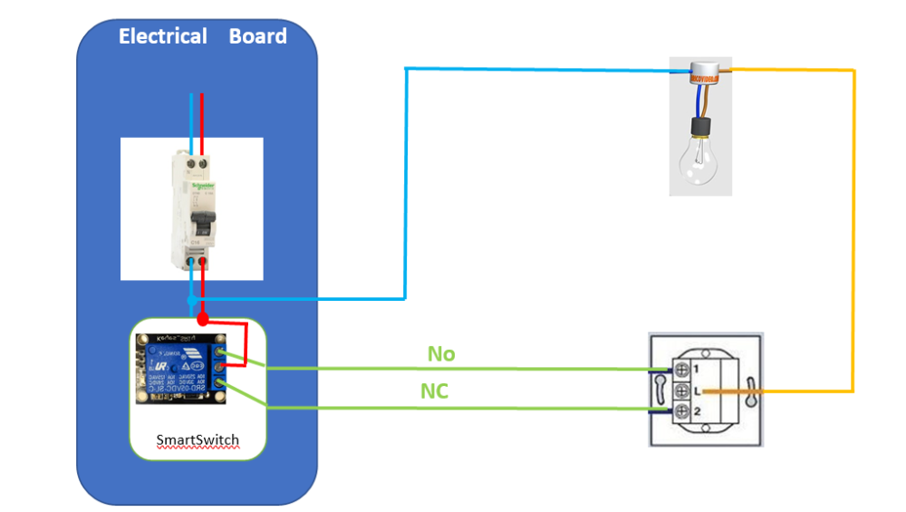
                                          I have tried on my side the system and it is working fine. However, i have modified the connection as the following picture in order to be able to insert the system directly into the main electrical board of the house to avoid having electronic cards behind each switch.
                                          Moreover, i connected the ACS712 on the "live" cable in serie with the COM output of the relay. In that case, i have no delay to display the status "ON", "OFF" in th controller.

                                          1 Reply Last reply
                                          0
                                          Reply
                                          • Reply as topic
                                          Log in to reply
                                          • Oldest to Newest
                                          • Newest to Oldest
                                          • Most Votes


                                          11

                                          Online

                                          11.7k

                                          Users

                                          11.2k

                                          Topics

                                          113.0k

                                          Posts


                                          Copyright 2019 TBD   |   Forum Guidelines   |   Privacy Policy   |   Terms of Service
                                          • Login

                                          • Don't have an account? Register

                                          • Login or register to search.
                                          • First post
                                            Last post
                                          0
                                          • MySensors
                                          • OpenHardware.io
                                          • Categories
                                          • Recent
                                          • Tags
                                          • Popular